
Introduction
Organic Rankine cycle (ORC) power plants for the conversion of thermal energy into electricity at temperatures ranging from
Scarce public technical information is available on low-temperature and low-capacity commercial ORC power plants. A U.S. company (Calnetix Technologies, n.d.) developed a system based on a hermetic assembly containing a radial-inflow turbine and permanent magnet generator on the same shaft supported by magnetic bearings (Yuksek and Mirmobin, 2015). The
The market potential of high-temperature/high-efficiency ORC systems with a power output from few kW to several hundreds kW is arguably very large and financial viability would greatly improve because of the higher conversion efficiency of the system, which in turn lowers the initial investment, which largely depends on the cost of the heat transfer surfaces of the heat exchangers. Applications include waste heat recovery from engines (gas turbines, internal combustion engines, and in the future high-temperature fuel cells) both stationary and propulsive (automotive, naval, and in the future possibly aeronautical), and industrial waste heat recovery. In case of high-temperature small-capacity ORC power plants, volumetric expanders cannot be realized due to the excessively large expansion ratio and a radial inflow turbine is arguably the best type of expander. However, suitable working fluids are made of very complex molecules, therefore the speed of sound of the expanding organic vapor is of the order of tens m/s and the flow within a single-stage radial inflow turbine is bound to be highly supersonic. Its design is thus challenging, both from the fluid dynamic point of view and because of many other aspects related to high rotational speed, sealing and bearings technology, and rotordynamics.
To the knowledge of the authors, the only small-capacity high-temperature/high-efficiency ORC power plant on the market is commercialized by a Dutch company (Triogen, n.d.). The power capacity is approximately 150 kW and toluene was selected as the working fluid. The turbine, electrical generator and feed-pump are contained in a hermetically sealed assembly and liquid toluene is used to lubricate the bearings of the high-speed rotor. The turbine configuration is rather unique, in that the flow direction is radial both at the inlet and at the outlet, and it is equipped with a radial-to-axial diffuser which, however, negatively affects fluid dynamic performance. Harinck et al. (2013) reported that the expander is designed to operate at
Research on high-speed, supersonic radial-inflow turbines (sRIT) for high-temperature and small capacity ORC power plants is ongoing because these are unconventional machines for which validated design and operational guidelines are not available. The turbine is the technological core of the system and the overall conversion efficiency depends to a large extent on the efficiency of the expansion process. Several works, see, e.g., the articles of De Servi et al. (2019), Cappiello and Tuccillo (2021), and Cappiello et al. (2022), describe the relevant flow features occurring in a sRIT and document best practices for their optimal thermo-fluid-dynamic design. For example, the numerical study of De Servi et al. (2019) shows that a sRIT may attain comparatively high fluid-dynamic efficiency
The ORCHID turbine is a
Experimentally characterizing the fluid dynamic performance of ORC turbines requires a setup that ensures stable and safe operation of the machine from start-up up to nominal and off-design conditions. A few test benches for small-scale ORC turbines are or have been operational throughout Europe. A facility for testing a
This article presents the layout of the ORCHID turbine rotor and documents the numerical methodology developed for performing the rotordynamic analysis of the assembly. A pocket gas seal (PGS) was designed for secondary flows management and its rotor dynamic characteristics modeled based on results of RANS computations. The rotordynamic coefficients of the squeeze-film-damper (SFD) cartridge were computed by numerical integration of the Reynolds equation, which was used to model the oil-film flow. A sensitivity analysis of the dynamic stability characteristics of the turbine rotor to some of the design parameters was also carried out.
Turbine test-rig
The ORCHID is a unique closed loop test-rig capable of delivering superheated or supercritical vapor of siloxane MM up to
Table 1.
Main design specifications of the ORCHID turbine.
To determine the rotordynamic coefficients and forces required by the rotordynamic model of the powertrain, the fluid dynamic performance of the stage in the whole operating envelope was characterized by means of single-passage RANS simulations, using a commercial solver (Ansys Inc., 2022). Figure 1 shows the isentropic expansion processes for four different turbine pressure ratios in the reduced temperature-entropy diagram of siloxane MM. Four values of the turbine inlet pressure, corresponding to those of the isentropes A, B, C, and D in the figure – respectively
Figure 1.
Isentropic (or ideal) turbine expansion processes (A–D) in the reduced temperature-entropy diagram of siloxane MM. The reduced temperature and entropy are defined as T r = T / T c r s r = s / s c r c r 0.44 bar
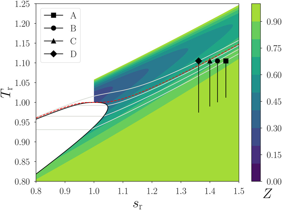
Figure 2.
Density ratio across the impeller (solid lines) and stage net power (dashed lines) as a function of the stage inlet total pressure for three rotational speeds. The values are calculated using the results of the RANS simulations.
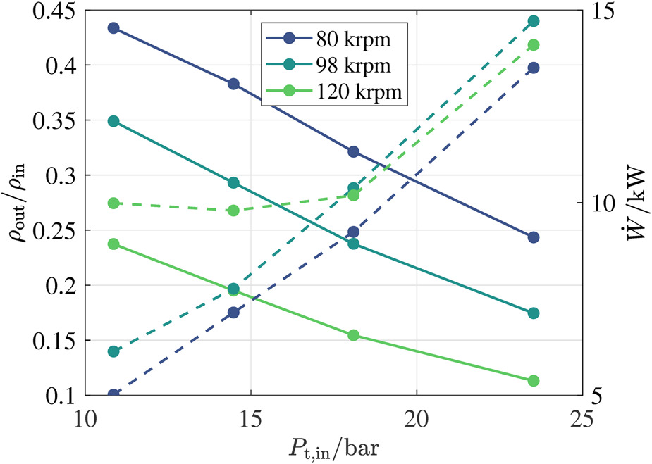
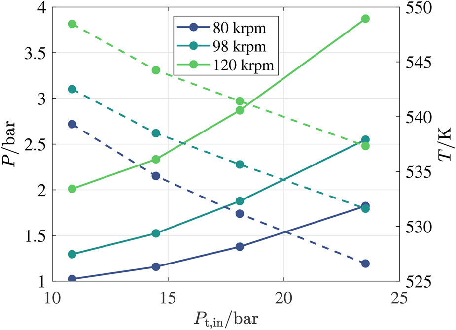
Figure 3.
Impeller inlet static pressure (solid lines) and temperature (dashed lines) as a function of the stage inlet total pressure for three rotational speeds. The values are calculated using the results of the RANS simulations.
Preliminary mechanical design
Key requirements of a turbine test-rig for research purposes are the possibility to test at different speeds and thermodynamic conditions, to obtain accurate measurements of all quantities relevant to performance characterization, to guarantee robust control of start-ups and shut-downs, and to be modular to ease the inspection and assembly of components.
Three main technical aspects were considered in the conceptual design phase:
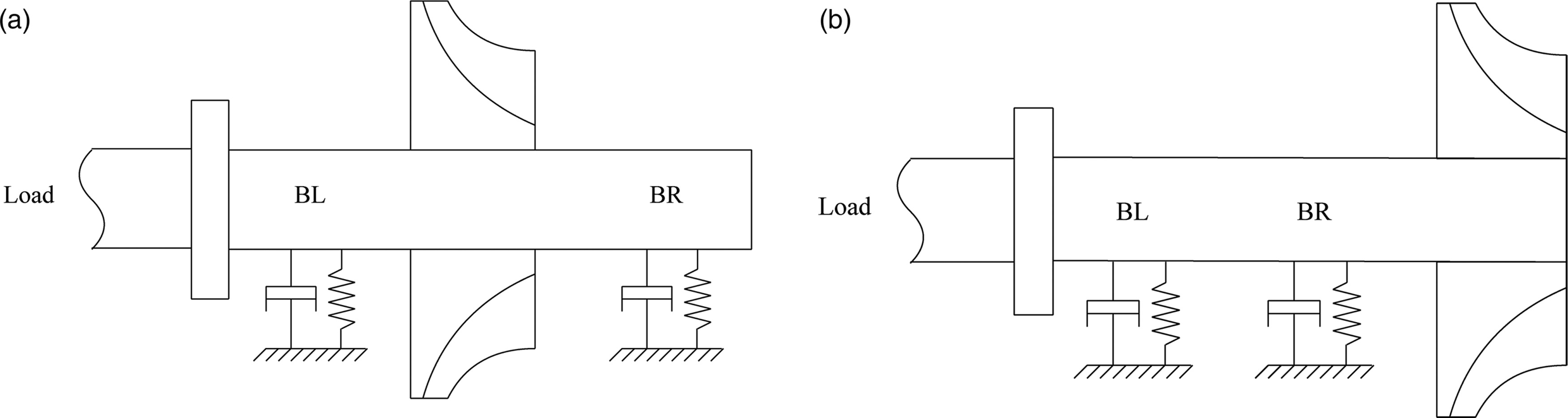
The turbine arrangement (straddled or overhung rotor).
The type of bearings (gas-foil, rolling element – REB – and active magnetic bearings).
The sealing arrangement, closely linked to the bearings type and turbine configuration.
The use of ceramic ball bearings for a turbine of this type provides two main advantages over competing technologies. Firstly, they can withstand substantially higher loads than gas-foil bearings, offering a robust solution for a wide range of operating conditions. Secondly, thanks to the widespread use of REB in a plethora of applications, they are available off-the-shelf and can be readily implemented within a new design. Recent trends in the design of turbocharger systems show that rolling element bearings can be preferable for compact, mobile systems such as automotive turbochargers (Schweitzer and Adleff, 2006), providing, even at high speeds, long term durability with lubrication and mechanical losses comparable to those of noncontact bearings (Nguyen-Schäfer, 2012).
Albeit the use of REB simplifies the assembly design, the need for lubrication poses additional challenges compared to gas-foil bearings. The oil contamination of the working fluid can severely impact the performance and integrity of the entire rig, causing mechanical damage to the rotating components due to erosion. Moreover, leaked oil accumulates and forms sludge, increasing the risk of thermal decomposition of the working fluid whenever in contact with hot spots in the rig. Therefore, the choice of a proper sealing technology is key to ensure safe and reliable operation of rotors supported on oil lubricated ball bearings. To prevent lubricant leakages, a common strategy adopted for large steam power plants is to use dry-gas seals (Forsthoffer, 2011), employing an inert gas like nitrogen as a barrier between the two fluid flows. As an alternative, contact seals capable of guaranteeing almost no oil leak are commonly adopted in low temperature and low speed applications. The advantage of the dry-gas solution is the absence of contact parts between the stationary and the rotating components, but this comes at the cost of a more complex rotor design. The use of dry-gas as a barrier requires also more components and more complex control strategies. Conversely, contact seals lead to a simpler and more compact assembly. The rotational speed and maximum operating temperature of ORC turbines is lower than those of turbochargers, therefore inexpensive contact seals can be used (such as those of the stationary lip seal type). Advancement in the development of low friction materials and temperature resistant coatings enables state-of-art contact seals to operate at peripheral speeds of up to
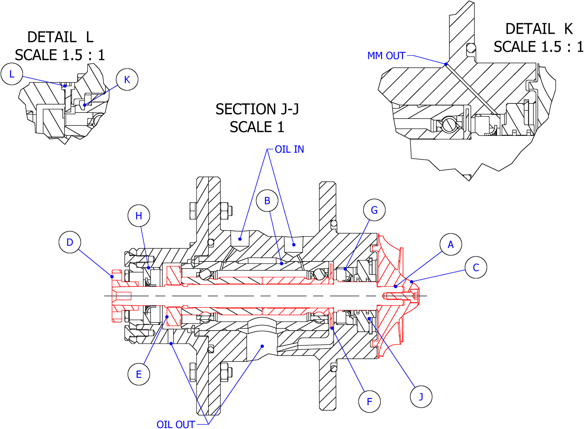
The conceptual layout of the rotor configuration obtained as a result of an iterative design process is shown in Figure 5. The rotor includes a shaft (A), a turbocharger cartridge (B), a turbine wheel (C), and a coupling flange (D). A lock-nut on the left side of the bearing inner raceway (E) is used to regulate the mounted-end-play of the rolling elements by adjusting the preload. The cartridge pushes axially against a stainless steel thin-disk (F), whose function is that of moving the oil outwards and to the main drain bore in the center of the assembly, through a cavity realized in the casing and extending
Rotordynamic modeling
The computation of the so-called rotordynamic coefficients, i.e., the stiffness and damping coefficients, is necessary to perform the assessment of the dynamic stability and characteristics of the rotor. External forces acting on the rotor-shaft due to the presence of the bearing cartridge SFD, the gas seal and the turbine impeller have been modeled and used to determine the system lateral vibrations through the stiffness and damping coefficients. The modeling approach is described in detail in the following.
Characterization of the dynamic response of the squeeze-film damper
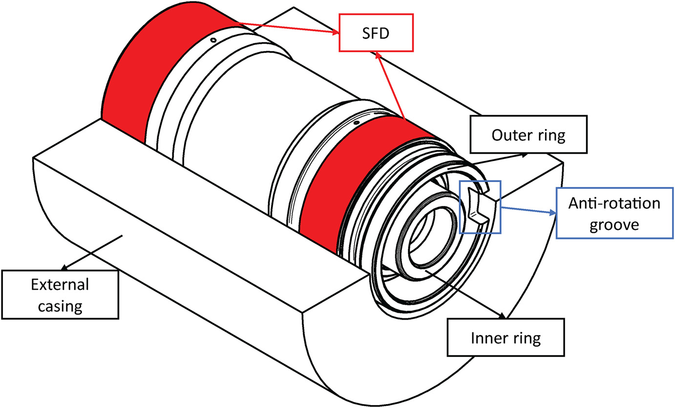
The main function of the bearing cartridge is to support the powertrain and to transfer the loads to the structure. A three-dimensional representation of the bearing cartridge is shown in Figure 6. The cartridge inner ring, having a bore diameter of
Figure 6.
Housing cut-off revealing the rolling element bearing cartridge. The red areas indicate the SFD lands.
The Reynolds equation describes the dynamic pressure generation in the oil film of the SFD. Considering the SFD radial clearance
The computer program developed and documented by Gheller et al. (2022) was modified to model the oil flow squeezing within the SFD. The program performs the numerical integration of the Reynolds equation
where
The powertrain design does not include a centering element for the external ring of the bearing cartridge. Thus, when the machine is not running the external ring of the bearing cartridge rests on the casing. As the rotational speed increases, the rotor excitation (e.g., residual unbalance forces) drives the outer ring far from the casing and generates the squeeze responsible for the oil pressurization. The ORCHID turbine is designed to operate at constant speed, and once the operating speed is reached, the motion of the outer ring reaches the so-called limit cycle. Full characterization of the limit cycle would require a transient simulation of the startup. At the level of preliminary analysis, a parametric study of the rotordynamic performance considering circular orbits and a vertical static eccentricity is conducted. Thus, the relation describing the oil-film thickness distribution over time and space in the tangential direction can be expressed as
where h is a function of the dynamic eccentricity, which in this work has been included using circular orbits of radius e in an orthogonal plane, and of the static eccentricity
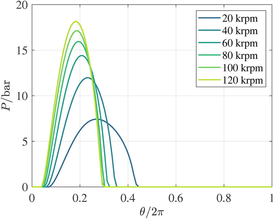
Equation 1 is numerically solved to compute the pressure distribution in the SFD for several shaft positions within a circular orbit. The orbit-based dynamic force coefficients are calculated as suggested by San Andres and Jeung (2016). Figure 7 illustrates the circumferential distribution of the pressure evaluated at the SFD midplane
The impact of the rotor eccentricity and of the orbit radius on the SFD direct damping and stiffness coefficients is displayed in Figure 8 for the design rotor speed of
Figure 8.
SFD stiffness and damping direct coefficients at 100 krpm ( e s / g ) ( e r )
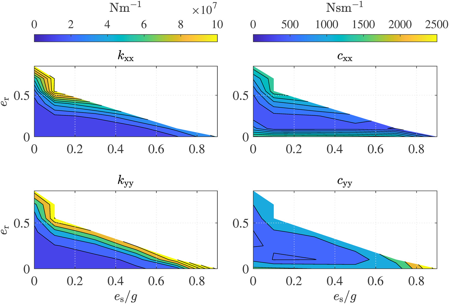
Considering the left contours of Figure 8, one can observe that the SFD generates increasing direct stiffness coefficients as either the orbit radius and the rotor eccentricity become larger. A squeezed oil-film interested by partial cavitation does not only generate a damping force, but also a centering force (Vance, 1998): the oil-film thus acts as a centering spring. With reference to the right contours, the damping provided by the SFD increases for either small and large orbit radii. This is due to the fact that, despite the portion of oil-film undergoing cavitation increases with larger orbits, the maximum pressure in the film also increases and compensates the detrimental effect of cavitation. As expected, the static eccentricity has a larger impact on
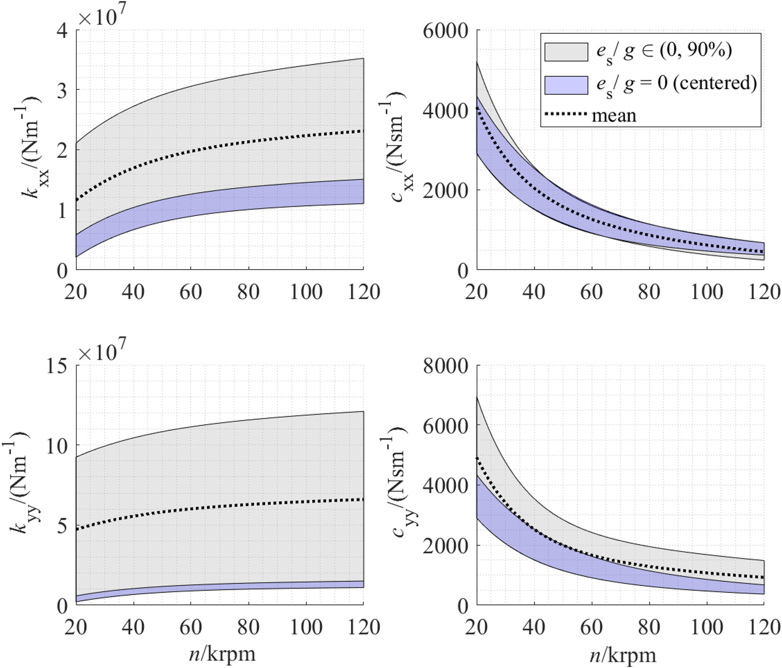
Previous study on oil cavitation in SFD (Zeidan and Vance, 1990) showed that once the so-called bubbly region is reached, oil pressure and thus damping characteristics stabilize even with a further increase of the vibration frequency. Moreover, larger SFD vibrations (thus larger orbits) cause larger pressure differences within the oil-film (San Andres and Jeung, 2016), causing larger portions of the film to cavitate. The dynamic response of the SFD has been analyzed for synchronous excitation with the rotational speed of the rotor. The evolution of the SFD dynamic coefficients with the rotational speed n is shown in Figure 9. Grey bands refer to the variation of coefficients with relative static eccentricities between 0 and
Figure 9.
SFD dynamic coefficient range for several values of orbit radius and eccentricity. The gray shaded bands are used to account for the variation of coefficients with relative static eccentricities between 0 and 90%, while the colored bands refer to the variation of rotordynamic coefficients with increasing relative orbit radii between 5 and 85% assuming a centered rotor. The dashed back lines indicate the average value.
Design and characterization of a pocket gas seal
The hot side lip seal chosen for this application, i.e., G in Figure 5, can seal up to 5 bar of pressure differential between the bearing cavity and the outside environment. Vice versa, even small pressure gradients would cause the entrainment of gas in the bearing cavity with negative consequences for bearing life. Thus, to prevent pressure build up on the impeller side of the lip seal, a gas seal was introduced between the impeller and the lip seal itself to cause a pressure drop of the pressurized siloxane behind the impeller disk. The selection of the seal type was performed by comparing the rotordynamic coefficients obtained with different types of seals. In particular, for the ORCHID rotor operating conditions and geometry, the calculation of the stiffness and damping coefficients was based on the experimental data for labyrinth seals (LS), fully partitioned pocket damper seals (FPDS) and honeycomb seals (HS) provided by Ertas et al. (2012), normalized following the approach of Childs et al. (1989). The calculation requires the shaft rotational speed, the seal type, length, diameter, the radial clearance and the pressure ratio across the seal. The pressure ratio across the gas seal of
Table 2.
Comparison of dynamic coefficients for different seal types.
| Seal type | ||||
|---|---|---|---|---|
| LS | 3,154 | 7,884 | 11 | 4 |
| FPDS | 15,768 | 18,922 | 39 | 26 |
| HS | 20,498 | 16,556 | 23 | 19 |
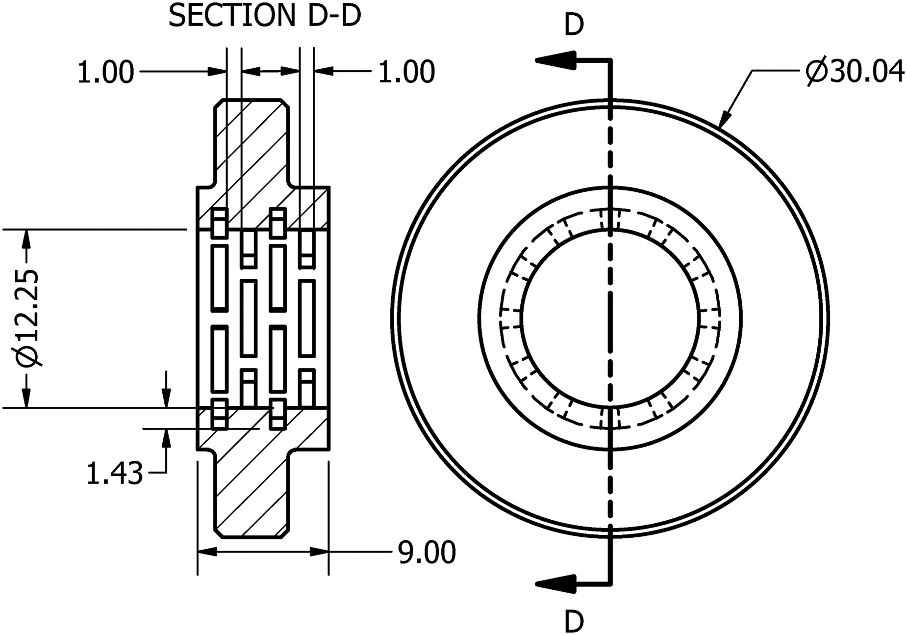
To minimize the destabilizing effects associated to traditional labyrinth seals and to avoid the geometrical complexity of FPDS and HS type seals, a pocket gas seal type (PGS) was designed. The PGS is essentially a labyrinth seal with internal swirl breakers, providing additional damping and dynamic stability as in FPDS and HS. The component was designed as a single-body, hollow disk made of stainless steel (AISI 316) with four rows of pockets acting as labyrinths. Adjacent rows of pockets were shifted relatively to each other to avoid preferential paths for the leaking vapor. The pockets extend
The pocket seal geometry and its relevant dimensions are illustrated in Figure 10. Additive manufacturing was chosen as production process for this component to allow geometrical freedom and to make the manufacturing cost-effective. Thin walls between adjacent pockets are arguably the most critical component feature from a manufacturing standpoint, therefore their thickness was chosen according to standard design guidelines for 3D metal parts (Ewald and Schlattmann, 2018). Novel printing techniques such as metal binder jetting are effective for manufacturing complex geometries, without requiring additional material for supporting the overhanging regions of the part (Blunk and Seibel, 2023). Nevertheless, material finishing by means of conventional manufacturing techniques will still be required to achieve the small dimensional tolerance required at the inner diameter of the PGS.
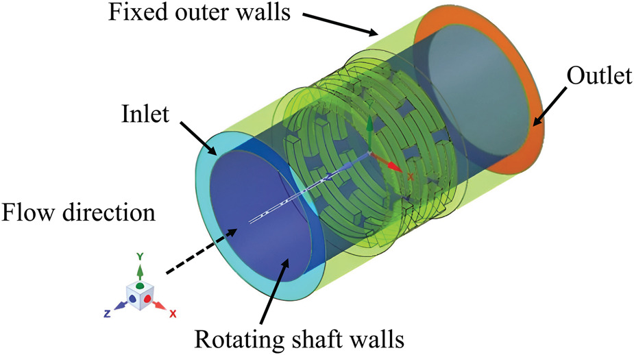
RANS simulations of the flow within the PGS were carried out to estimate the leakage mass flow and the dynamic coefficients (i.e., stiffness and damping) at the nominal operating conditions of the rotor. A commercial CFD solver (Ansys Inc., 2021) was used for this study, and the computational domain displayed in Figure 11 was discretized using a hybrid approach comprising an unstructured mesh body and a structured layer near the walls. The domain was extended at the inlet and outlet of the PGS-shaft clearance gap as shown in the figure to prevent boundary conditions from influencing the flow solution inside the domain. The fluid domain geometry has been simplified to reduce the computational cost of the simulation, and because the objective of the analysis is to predict the flow motion within the clearance between the PGS and the shaft. Thermal deformation of the seal geometry due to temperature gradients has been neglected, as a result of the minimal temperature drop of just
Figure 11.
Computational domain used for the CFD flow simulations of the PGS. The employed boundary conditions are also indicated. The flow through the geometry of the gap between the shaft outer surface and the PGS inner surface is modeled.
The discretized computational domain comprised 5.1 million cells as a result of a mesh independence study. Local inflation was added at non-slip walls (i.e., shaft and PGS surfaces) to properly resolve the boundary layer, while the dimension of the cells was adjusted in the clearance region to maintain the maximum
Table 3.
Boundary conditions for gas seal CFD simulations.
| Quantity | Inlet | Outlet |
|---|---|---|
| 1.7 | – | |
| 534 | – | |
| – | 1.0 | |
| 98.1 |
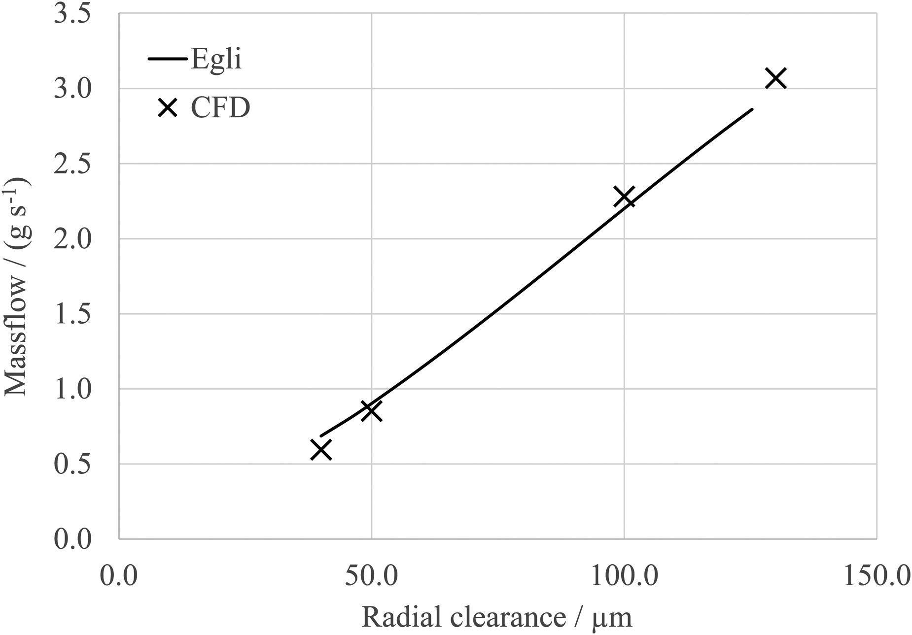
The leakage mass flow rate of siloxane MM computed from CFD was compared with the predictions from an empirical method commonly employed in gas turbine engines (Ludwig, 1980), namely the Egli model of labyrinth seal flows (Egli, 1935). Figure 12 shows the comparison of the massflow rate through the PGS predicted by the Egli model and by the CFD as a function of radial clearance c. Despite the Egli model is rigorously valid for labyrinth seal geometries, the mass flow predicted by the two models is in close agreement and varies linearly with the increase in the radial clearance.
Figure 12.
Leakage massflow rate through the PGS as a function of the radial clearance. Comparison between CFD results ( × )
For the estimation of the rotordynamic coefficients, the forces in the horizontal and vertical directions acting on the shaft,
where the denominators are the imposed displacements and displacement rates, whose magnitude was determined by means of a convergence study in which their value was varied until stiffness and damping coefficients reached asymptotic values for small amplitude vibrations.
Figure 13.
Stiffness (a) and damping (b) coefficients computed with CFD simulations. Dotted lines are linear fits used as input for the rotordynamic analysis. The symbols indicate direct ( ◯ ) ( △ )
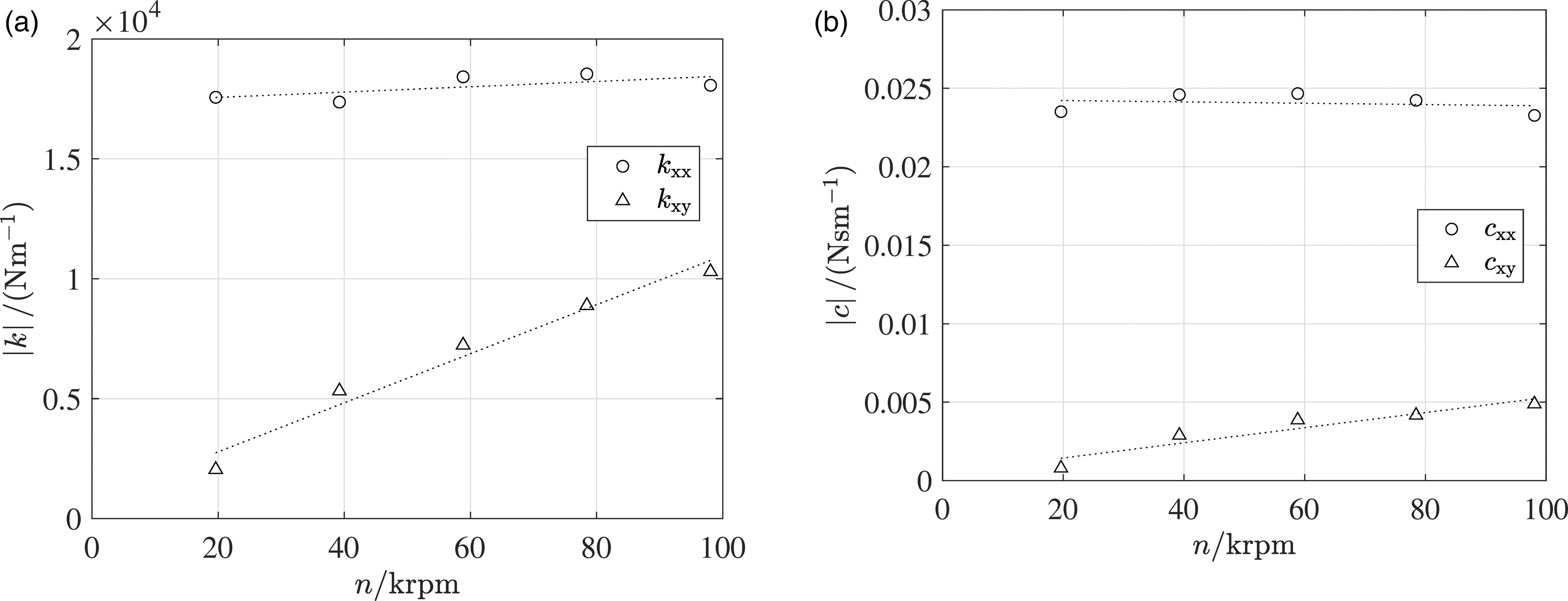
At low speed, direct stiffness coefficients are the responsible for most of the PGS stiffness, while the contribution of the cross-coupled stiffness is important only at higher rotational speeds. According to Ertas et al. (2012), seals are characterized by cross-coupled stiffness coefficients opposite in sign which can lead to rotor instability. This is also the case for the PGS considered in this work. The terms on the secondary diagonal of the stiffness matrix are of opposite sign, though their magnitude is similar, i.e.,
The rotordynamic coefficients computed with the CFD model have been compared to those obtained using the empirical correlation by Ertas et al. (2012) for the honeycomb seal type. Even if the geometry is different, the empirical correlation provides results similar to those obtained with CFD, as reported in Table 4. The prediction of the cross-coupling stiffness by means of the two models differs by about
Determination of the impeller fluid-structure interaction forces
Fluid-structure interaction (FSI) forces in fluid machines are often responsible for rotordynamic instabilities, potentially damaging the components and in some cases leading to catastrophic failure of the entire system. Unsteady flows in rotor-shroud clearances due to unsteady pressure fields and rotational eccentricities are responsible for the generation of non-axisymmetric pressure fields that cause forces perpendicular to the axis of rotation (Alford, 1965). San Andres (2023) performed an extensive review of the different methods to predict the magnitude of destabilizing forces due to this dynamic forcing using both semi-empirical methods, such as those of Alford (Alford, 1965) and Wachel (Wachel and von Nimitz, 1981), and more advanced methods based on CFD (Moore et al., 2010).
In this study, the destabilizing aerodynamic force coefficient has been predicted according to the Wachel formula (Wachel and von Nimitz, 1981), i.e., the standard method for radial expander-compressor systems (API, 2002). The model allows one to estimate the stiffness coefficient contributing to the systems lateral vibrations
where
The destabilizing cross-term was computed for the different operating points of the turbine, using the fluid density ratio and the stage power determined by means of CFD simulations at different operating conditions and plotted in Figure 2. Solid lines in Figure 14 depict the values of
Figure 14.
Cross-coupled stiffness coefficient k x y
Consequently, the largest computed value of
Rotordynamic analysis
The dynamics of the turbine assembly has been investigated by means of a finite element rotordynamic beam model. The model includes those of the shaft train, of the REB cartridge accounting for the SFD characteristics, of the pocket gas seal and of the aerodynamic forcing of the turbine wheel. The graphical representation of the resulting rotordynamic model, made of finite beam elements, is schematically shown in Figure 15, together with the non-rotating cartridge outer ring. The rotating parts include the coupling hub and flange, the bearing lock-nut, the cartridge inner ring, the impeller and the ogive. The presence of a coupling shaft – used to direct-drive a high-speed generator attached to the coupling hub D illustrated in Figure 5 – has been modeled by adding its mass and inertia as lumped parameters on the second element from the left in Figure 15.
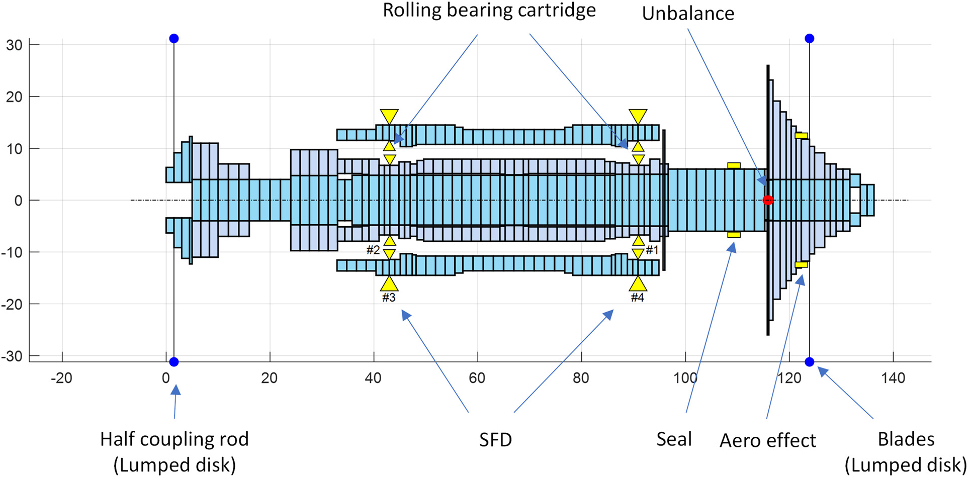
Figure 15.
Schematic graphical representation of the rotordynamic model showing the mass distribution of the rotor discretized using disks. The locations where the most important rotordynamic coefficients have been applied as lumped parameters are shown by means of yellow arrowheads. These include the REB stiffness, the SFD damping, the PGS stiffness and damping and the impeller FSI stiffness. The residual unbalance computed as per ISO1940-1 standard is indicated by the red dot, while the coupling disk and the impeller blades lumped masses are indicated by the blue dots. x y mm
The lateral vibrations of the structure are described by the linearized system of equations
where
The dynamics of the REB is modeled through linearized coefficients using the classical stiffness and damping matrices
Table 5.
Constant direct stiffness and damping coefficients used in the rotordynamics calculation.
| Location | ||
|---|---|---|
| Impeller side | ||
| coupling side |
The effect of the squeeze-film-damper is considered by introducing a stiffness and a damping matrix with non-null direct terms and null cross-coupled terms
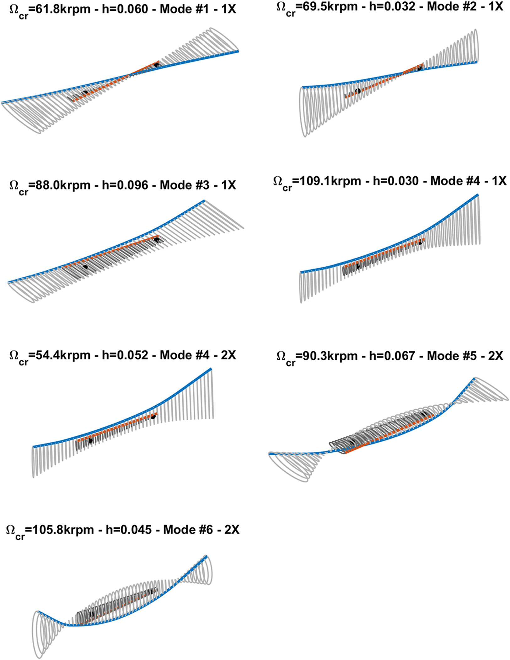
The result of the eigenfrequency analysis as a function of the rotational speed is reported in the Campbell diagram of Figure 16. Fundamental and first harmonic critical speeds, hence the excitation frequencies at which the modes damped natural frequencies cross the 1× and the 2× lines in Figure 16, have been reported in Table 6 along with the corresponding damping factors in the range of rotor speeds going from
Figure 16.
Campbell diagram of the ORCHID turbine rotor. The solid lines indicate the damped natural frequencies associated to each vibration mode up to 5 , 000 Hz
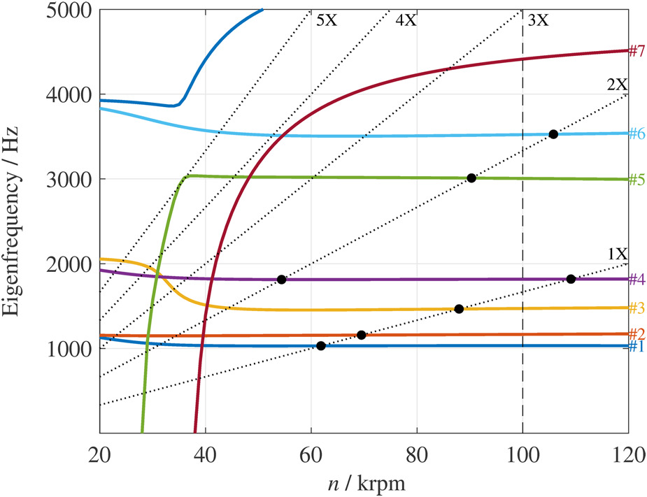
Table 6.
Critical speed and damping ratio of several modes crossing the 1× and 2× shaft excitation frequency.
| Mode # | Critical speed/ | Damping ratio |
|---|---|---|
| 1 (1×) | 61.8 | 0.060 |
| 2 (1×) | 69.5 | 0.032 |
| 3 (1×) | 88.9 | 0.096 |
| 4 (1×) | 109.1 | 0.030 |
| 4 (2×) | 54.4 | 0.052 |
| 5 (2×) | 90.3 | 0.067 |
| 6 (2×) | 105.8 | 0.045 |
Figure 17.
Mode shapes at the critical speeds reported in Table 6. The solid blue line represents the shaft center line, while the red line indicates the cartridge outer ring center line. Orbits described by the two center lines are represented in grey.
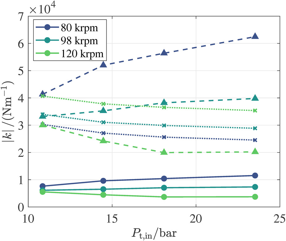
The coloured bands shown in the Campbell diagram of Figure 18 illustrate the range of variation of the eigenfrequency of each vibrating mode for variations of
Figure 18.
(a) Campbell diagram of the rotor system as a function of shaft speed. The colored bands indicate the impact of a varying bearing stiffness in an interval ± 30 % 100 krpm
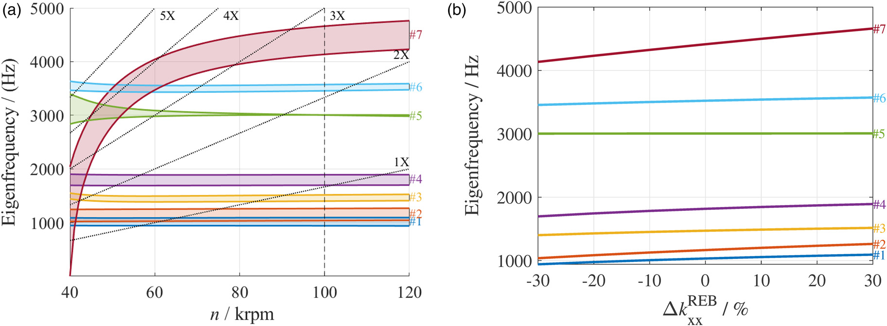
The rotor is composed of many parts stacked together for construction simplicity. If the shaft vibrates under the action of a bending mode, micro-sliding in the circumferential direction of radially fitted parts can occur. This phenomenon, called internal damping, is a possible source of instability if the machine operates largely above the first critical bending speed. The current analysis shows that the machine operates in a sub-synchronous regime concerning modes 5 and 6 (first bending modes) at the nominal speed of
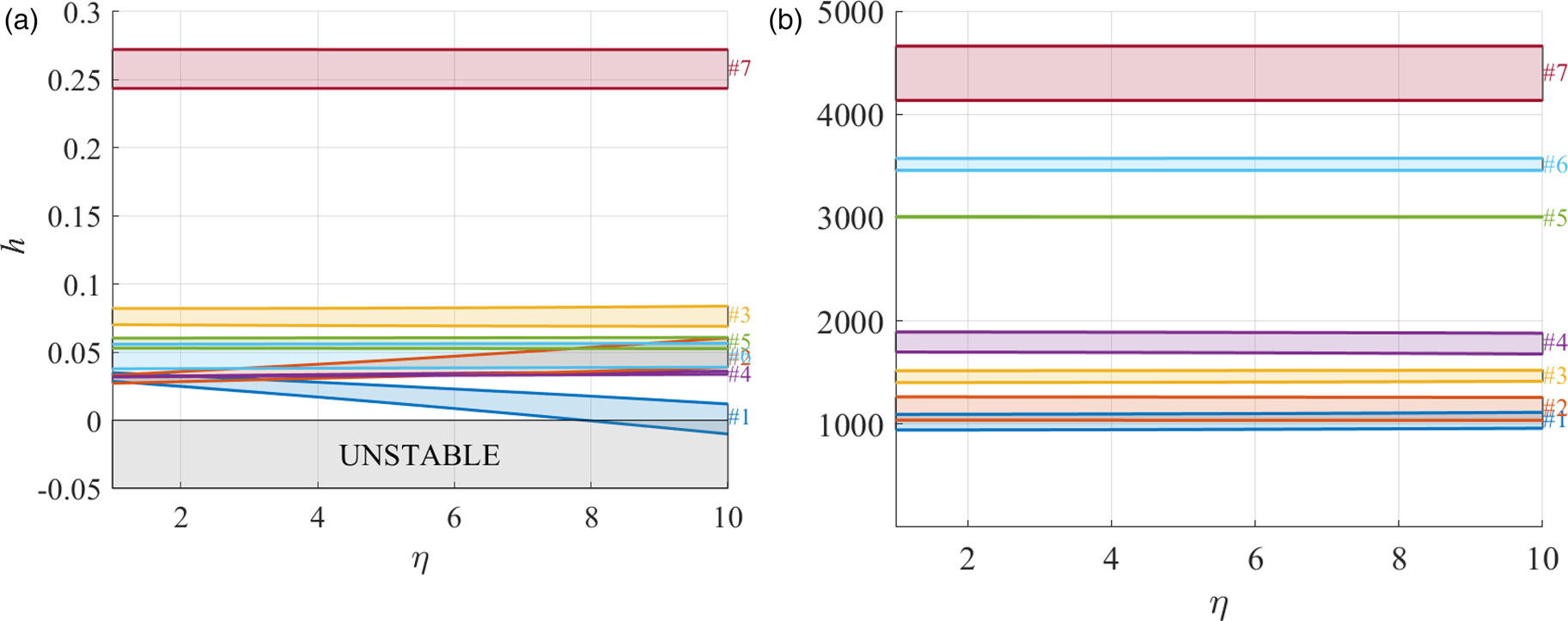
The stability of the rotor was investigated by evaluating the damping factor h of each vibrating mode at the nominal rotational speed. The damping factor is defined as
Conclusion
This paper documents the mechanical design and rotordynamic analysis of the high-speed rotor of the ORCHID turbine. The bearing unit selected to support the overhanging turbine wheel and coupling hub flange is a turbocharger ball bearing assembly. The component features an external cartridge that acts as a squeeze film damper, providing damping to the shaft-train. The damping coefficients of the cartridge were computed numerically throughout the entire operating range of the machine, considering a nominal radial clearance of
A pocket gas seal was designed in-house to limit the leakage flow rate of working fluid to the bearings housing. The leakage massflow rate calculated by means of RANS simulations was compared to the value obtained with an empirical method commonly employed for the sealing design of gas turbines. Predictions from the CFD and the empirical method were in close agreement, showing that such an empirical correlation is applicable for the estimation of the leakage mass flow rate through pocket gas seals of high-speed ORC turbines. Moreover, RANS simulations were carried out to compute the stiffness and damping coefficients of the pocket gas seal. The results show that this type of gas seal leads to comparatively small direct and cross-coupled stiffness terms, which were included in the rotordynamic analysis to evaluate the impact of the seal on system stability. Conversely, the damping provided by the pocket gas seal is negligible compared to that of the squeeze film damper, being about 5 to 6 orders of magnitude lower.
The analysis considers also the presence of destabilizing aerodynamic forces due to the fluid-structure interaction between the unshrouded impeller and the casing. Predictions obtained with the Wachel and the Moore & Ransom model have been compared, showing reasonable agreement between the force magnitudes for preliminary calculations. Higher fidelity methods such as unsteady RANS simulations should however be used for a more accurate assessment.
The lateral vibration analysis of the first 7 mode shapes reveals the presence of rigid modes (1 and 2) and flexible modes (from 3 to 7). A sensitivity analysis was carried out to investigate the impact of modeling assumptions on the results of the rotordynamic analysis. In particular, mode #7 exhibits a large sensitivity to variations of
Finally, the stability of the rotor was assessed by investigating the change in damping ratio h of each mode shape for increasing values of the cross-coupled stiffness coefficients associated to the impeller-shroud aerodynamic force, and of the PGS stiffness coefficients. The analysis highlights that mode #1 becomes unstable only if values of the cross-coupled stiffness coefficients are about one order of magnitude larger than those estimated in this study. Nevertheless, since the computation of the destabilizing stiffness term (especially the impeller-shroud force) is subject to large uncertainty, the analysis presented here is purely indicative of a worst case scenario and further investigations are necessary to properly evaluate its impact on system stability.
Future work will be devoted to the testing of the rotor, properly instrumented with embedded sensors to measure the vibration amplitude at different rotational speeds, and to characterizing its transient dynamics. Moreover, more in depth numerical investigations using higher fidelity models, such as full-annulus unsteady RANS simulations, are considered necessary to obtain further insight about the destabilizing nature of the cross-coupled stiffness coefficients resulting from the impeller secondary flows.