Introduction
Conventional power plants must compensate fluctuations in the power supply because of an increasing amount of volatile renewable energy sources such as wind and solar power. This demands more flexible conventional power plants. Gas turbine power plants adjust total power output quickly but CO and UHC emissions limit the part load regime to about 60% of the full load. This study focuses on the operational range extension of gas turbines in a combined cycle power plant to lower loads. The basic idea to accomplish this goal is to increase the reactivity of the fuel and to reduce the possible overall equivalence ratio in the combustion chamber without risking increased emissions, flame out or combustion instabilities. The desired increase of reactivity is achieved by converting methane to hydrogen.
There are mainly three different approaches to convert methane to syngas with high hydrogen content: partial oxidation (POX), steam reforming and autothermal reforming 20.
POX is a combustion process in the very rich regime. Thermodynamic equilibrium is shifted towards carbon monoxide and hydrogen due to the deficiency of oxidizer. Usually a catalyst is used to increase the reactivity of the mixture. Regarding conversion to hydrogen and residence time the studies of 04 and 08 show that POX with an affordable nickel catalyst shows promising results. However, the produced syngas has a very high temperature, which impedes premixing due to auto-ignition, and thus a clean burn out in the combustion stage. Cooling the syngas to reach a temperature which allows for premixing can only be achieved with a significant pressure loss that incorporates a heat exchanger.
The second route to produce syngas is steam reforming 12. In steam reforming, natural gas is mixed with water vapour. Water and natural gas react mainly to carbon dioxide and hydrogen. Usually steam reforming is performed with a high excess of vapour to avoid coking of the nickel catalyst and to increase the hydrogen yield. The reaction is highly endothermic (
The third process to produce syngas is autothermal reforming. An autothermal reformer (ATR) can be seen as a combination of the two aforementioned processes 24. Natural gas is mixed with an oxidizer and water vapour and reacts on the surface of a catalyst. The exothermic oxidation reactions provide the necessary heat supply for the endothermic steam reforming reaction. By adjusting the ratios of oxidizer to carbon bound in methane (Air/C) and water to carbon (H2O/C), it is possible to control the temperature of the process and the products. The ATR is analysed in this study, because the moderate syngas temperature (below 1,000 K) allows for premixing, no external heat supply is needed and the residence time for the conversion is reasonable.
Fuel reforming prior to combustion has been particularly in the focus of researchers because of its potential to CO2 sequestration. The high partial pressure of CO2 in the syngas provides the potential for membrane or chemical sequestration 13, 25. Several studies on fuel reforming for flame stabilization have been published in the past: Bozza et al. investigate the use of the enthalpy of the exhaust gas to reform the fuel 01. In CCPPs, this enthalpy flow generates steam for the steam turbine. Extraction of large amounts of exhaust gas enthalpy has a negative influence on overall plant efficiency. 19 discuss the possibility of exhaust gas recirculation, which has an equally negative effect on the Heat Recovery Steam Generator (HRSG) performance. A similar process is analysed by 07, but to enhance reactivity of biogas. All the aforementioned processes are designed for a stand-alone gas turbine process and cannot be implemented in CCPPs. Karim et al. deal with a catalytic rich quench lean process 09, 16, 22. A rich fuel air mixture is ignited catalytically. The reactor is cooled by bypassing air. For an effective cooling, the areas must be sufficiently large. This in turn increases the pressure loss. The authors do not mention how the pressure loss of the rich catalytic stage is thought to be compensated. In the present study, fuel reforming prior to combustion suitable for the integration in CCPP is analysed with respect to the general feasibility of the concept and the potential improvement of the turn-down ratio.
The paper is organized in the following manner. Firstly, the syngas generator is described in detail. In the main section, models for all components of the syngas generator and the gas turbine based on simple equations are presented. The components include an ejector, a catalyst bed, the syngas injection, the compressor, the combustion chamber, the turbine, and the HRSG. Thereafter the results of the model are discussed. Then a kinetic study shows the conversion of natural gas to syngas for the fuel processor. This is followed by the calculation of the laminar flame speed and the Damköhler number of mixtures of methane and syngas to assess the possible stability gain of the gas turbine in the part load regime.
Integration of the syngas generator for part load operation in a combined cycle power plants
Figure 1 shows a CCPP process scheme with the catalytic reactor driven by an ejector. In full load operation of the gas turbine, the compressed air is entirely directed to the combustion chamber, where it is mixed and reacts with NG. The resulting hot gas drives the turbine, which itself drives the compressor and a generator (not shown). The ejector and the fuel processor are placed in a parallel flow configuration and are only used in the part load regime. In order to reduce power below full load the fuel mass flow is reduced as usual. This measure is limited by the lean blow out (LBO) limit of the fuel. Further power reduction is achieved by simultaneously throttling the compressor air intake and the fuel mass flow, at a constant combustion temperature. With state of the art compressors intake can be reduced to ~70% of the full load air mass flow. At this point, LBO limits the power reduction again. This is where the fuel processor is activated. Steam generated by the HRSG is used to boost a small fraction of the compressed air to higher pressure. This air is directed through the fuel processor. Natural gas is mixed with this air and water vapour flow. This mixture is then converted to syngas at the catalyst. Finally, the syngas is injected into the combustion chamber in parallel with the remaining natural gas. The syngas and natural gas mixture has a higher reactivity than natural gas alone and is thus suitable to combust at a lower equivalence ratio. The lower equivalence ratio results for a constant air mass flow in less fuel and thus the total power output can be reduced.
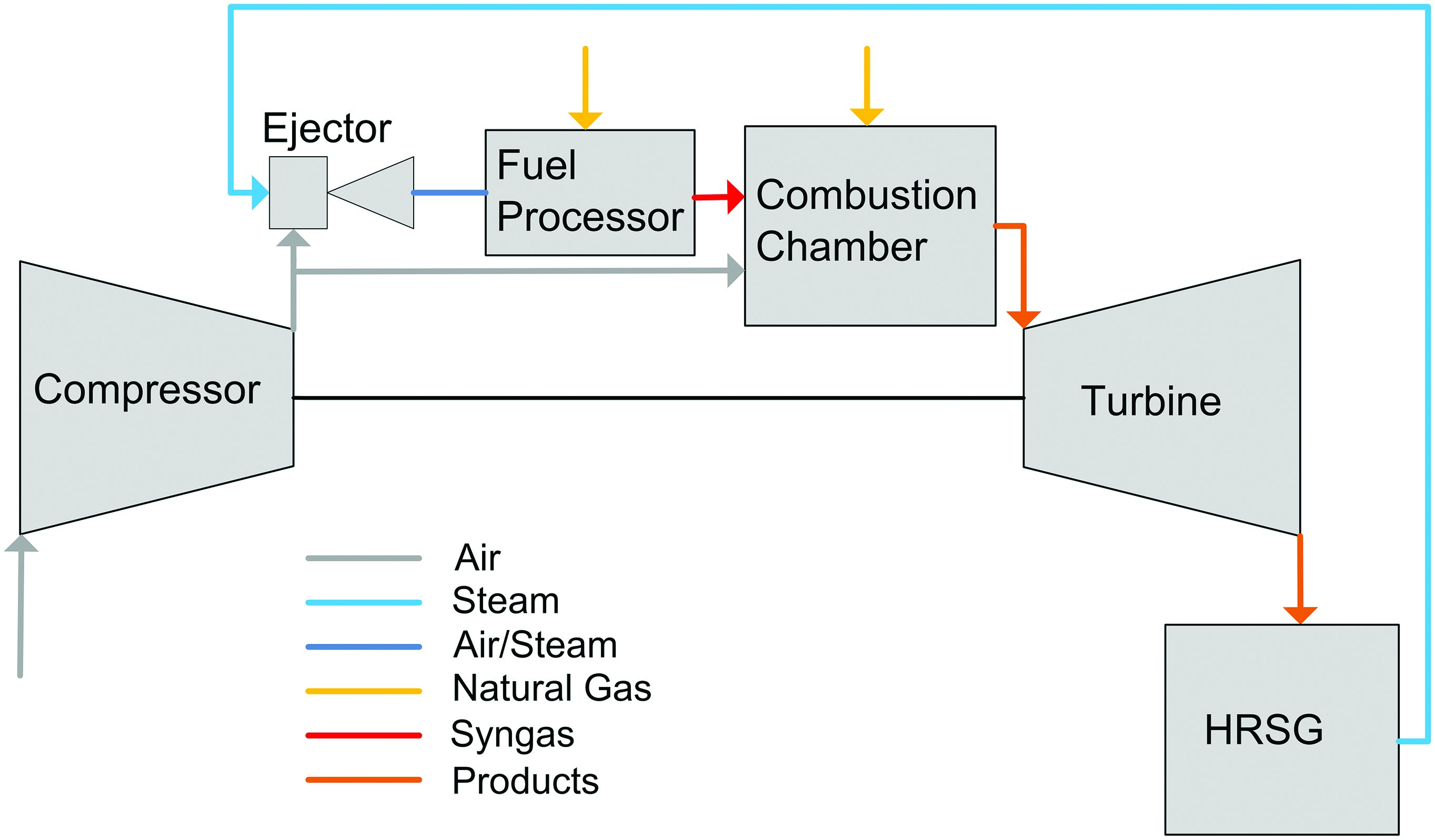
The operation of a fuel reformer directly upstream of the combustor leads to some challenges regarding the system integration. One of the challenges is the pressure loss this bypass incorporates. The air exiting the compressor is split into two flows: one for the catalytic reactor, which produces syngas to be injected into the combustion chamber, and the second that is led directly into the burners of the combustor. For this reason the driving pressure for the syngas generator must be generated. In order to achieve reforming in a compact device a catalyst must be employed. Literature on syngas generation indicates that nickel catalysts are most favourable for reforming because nickel exhibits high activity at low catalyst cost. Problematic is the high light-off temperature of the nickel catalyst. Light-off temperature of nickel catalysts are at least 700 K 26. If the temperature of the mixture of compressed air, steam and natural gas is too low for a nickel catalyst to achieve ignition, a second catalyst with a lower light-off temperature must be employed. For the ignition, a platinum/palladium catalyst can be implemented. The operation of the catalytic fuel processor is accompanied by a significant pressure loss. By the integration of an ejector upstream of the reactor, this pressure loss can be compensated. The ejector is driven by the high-pressure steam extracted from the HRSG. In full load operation this steam has approximately a temperature of 800 K and a pressure of 120 bar 05. The catalysts perform well within a certain temperature range. Below this range the activity is lost — above it the catalyst is damaged. Therefore, syngas temperature is a crucial parameter for the design of the syngas generator.
In the following, a detailed model is introduced which allows to identify the limits of the operating range of the catalytic reactor as function of the mass flow of steam and air related to the natural gas flow at inlet of the reactor, as these two ratios are the only free design parameters.
Model of the syngas generator integrated in the gas turbine cycle
The compressor, the ejector, the catalyst bed, the combustion chamber, the turbine, and the HRSG are modelled focussing on the necessary information to evaluate the feasibility of the syngas generator concept. The model is based mostly on analytic equations. For some parameters, e.g. the adiabatic efficiency of the compressor or the steam data, look-up tables are used. Details of the modelling for each component are given below. After the description of the components, the solution algorithm and the results are discussed. The model can also be used to investigate the sensitivity of the process to certain input variables. For this reason, a sensitivity analysis is additionally presented.
Syngas generator
The syngas generator comprises the ejector and the catalyst bed.
Ejector pump
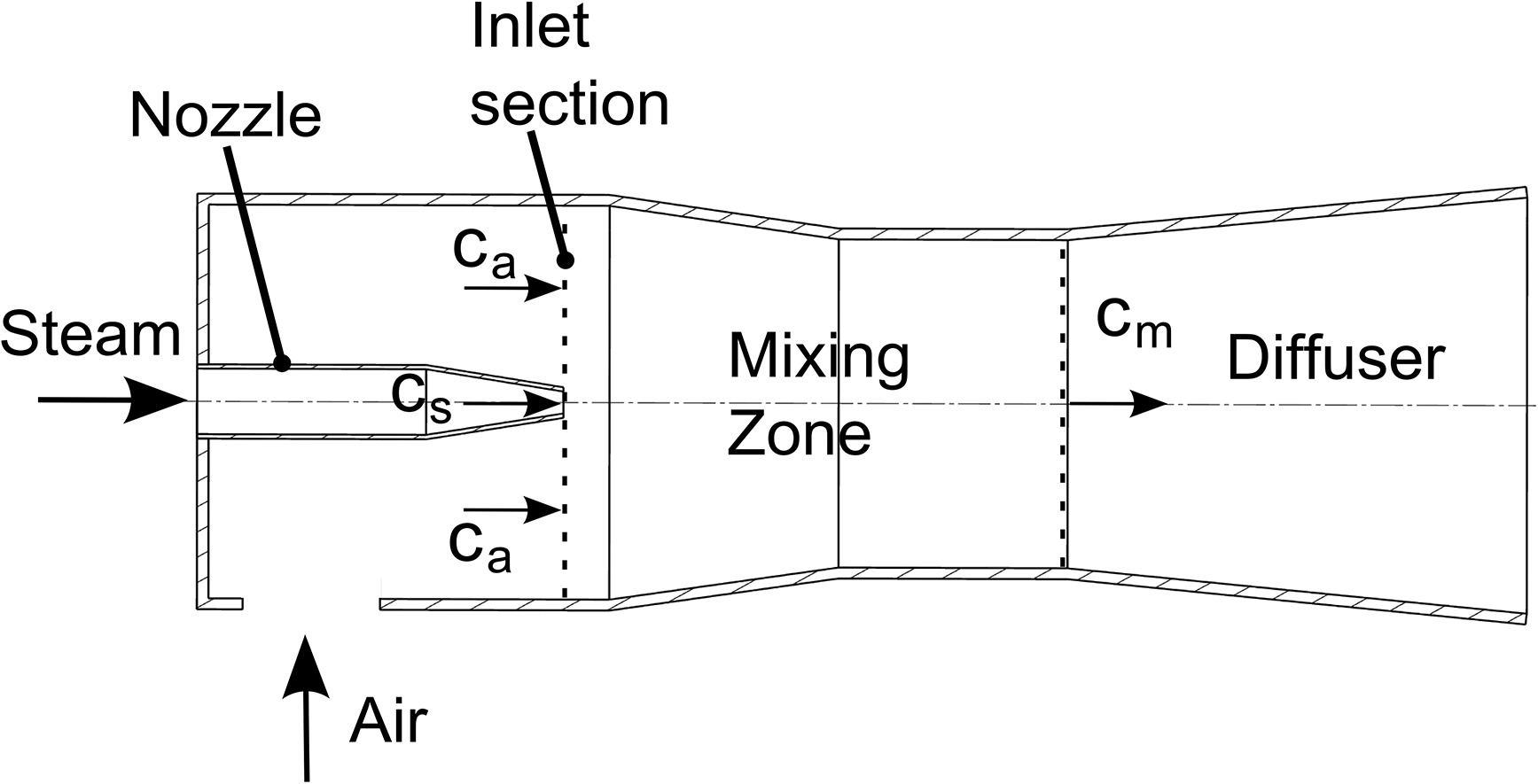
An ejector pump comprises a nozzle for the driving fluid, an inlet for the driven fluid, a mixing zone, and a diffuser (see Figure 2). Details on the operation and performance of ejector pumps can be found in 27. In the present case, a Laval nozzle is used to attain supersonic conditions. In the nozzle, kinetic energy of the steam is generated with very high efficiency. The driving jet exits the nozzle and entrains the air. The mixing process is nearly isobaric, but involves some friction losses. In the diffuser downstream of the mixing zone the kinetic energy is reduced continuously associated with a pressure gain. The mixture pressure at the exit of the ejector pump is between the pressures of the driven and the driving fluid.
For the isobaric mixing zone 17 the momentum balance reads as follows:
is solved for the mixture velocity cm as a function of steam and air velocities (cs, ca), mass flows (
Introducing these equations in the momentum balance and solving for the mass flow ratio of interest, i.e. steam to air, gives:
Here the
The unknown enthalpy differences are treated as follows. The enthalpy difference
Catalyst bed
For the catalyst bed, the temperature of the products and the pressure loss are of importance. The temperature of the products must be within a certain range to avoid overheating and damaging of the catalyst and to maintain reactivity. This range is assumed to be 900K = Tmin < Tsyngas < Tmax = 1,123 K based on data from literature. The thermodynamic equilibrium based on minimization of the free Gibbs energy is calculated for the mixture of methane, air, and water vapour in the reformer. The species involved in these calculations are CH4, CO2, CO, solid carbon, H2O, H2, O2, and N2.
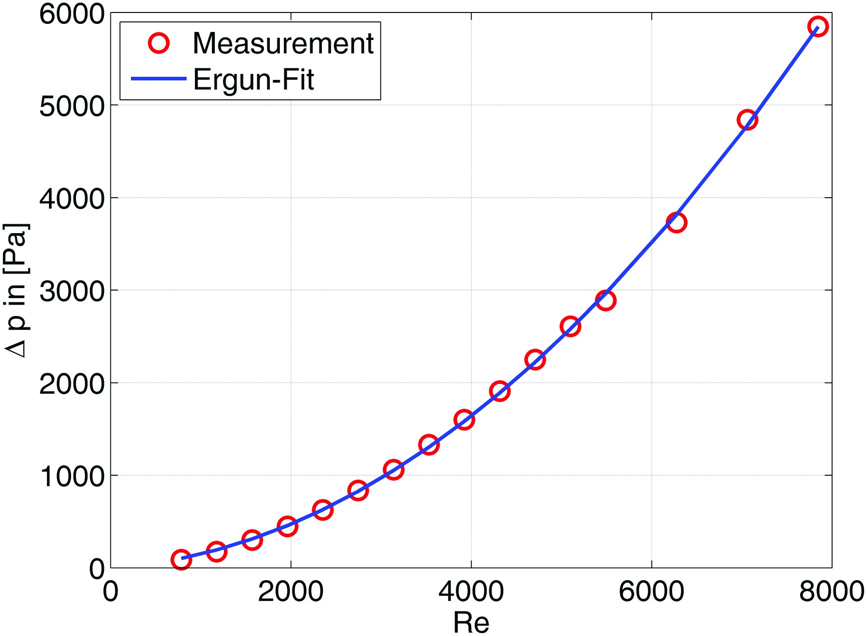
The pressure loss of a catalyst consisting of pellets can be calculated according to the Ergun equation 06:
For the employed nickel catalyst the Sauter diameter
The coefficients A and B in are fitted to pressure loss measurements with cold-air performed on a generic tube reformer filled with commercial 10-hole rings. The Reynold’s number Re is defined with the cold-air properties, the superficial velocity, and the Sauter diameter as characteristic length scale. The measurements and the corresponding fit are presented in Figure 3. For the reacting case, the fluid parameters such as density and viscosity change over the length of the reactor. In this case, the reactor is discretized into ten segments and the fluid parameters are adjusted to the change in composition and temperature. It is further assumed that in the reformer the aforementioned equilibrium is reached at the outlet and that the composition changes according to an exponential decay towards the equilibrium composition. This corresponds well to the simulated change in composition that is described later in this study. The residence time is assumed 0.2 s. The size of such a reactor is given in .
Syngas injection and further losses
As already mentioned, the syngas injection is another major source of pressure loss. As the pressure loss is a linear function of the dynamic pressure according to , the velocity has a crucial influence on the pressure loss. For the injection velocity of the syngas, cinj = 100 m·s-1 is assumed.
The constant a takes different values depending on the case for which the pressure loss is calculated. Total pressure loss for the piping and the injection reads:
The pressure loss for the injection is of order of 2.0 × 10⁴ Pa.
Gas turbine and heat recovery steam generator
In the following the models for the compressor, the combustion chamber, the turbine and the HRSG are presented in detail. A generic gas turbine and HRSG with the parameters as shown in the are assumed.
Compressor
A polytropic change of state is assumed for the compressor; see . When the syngas generator is in operation in the part load regime, the inlet guide vanes (IGV) are assumed to be closed thus reducing the total air intake to 70% of the full load operation. Closing the IGV reduces the polytropic efficiency of the compressor. With 70% of the nominal air intake this efficiency is ηpol,c = 0.8 according to 03. Data that is more recent has not been found but the compressor’s efficiency has only a minor influence on the results of this analysis. The compressor outlet pressure is assumed to decrease linearly with the air mass flow.
The polytropic exponent for the compressor is calculated as follows:
Combustion chamber
Here the calculation of the hot-gas temperature is of interest. An energy balance is solved. A total equivalence ratio of 0.33 is assumed for the model of the combustion chamber. This can be seen as a goal to be reached by the syngas injection. The adiabatic flame temperature TCC is calculated based on total fuel consumption. As combustion efficiencies are above 98%, this is a reasonable assumption. NASA polynomials are used for all species involved.
Turbine
A polytropic change of state is also assumed for the turbine; cf. . As the influence of the polytropic efficiency is of minor importance for the syngas generator, a constant value of ηpol,turb = 0.95 11 is assumed.
The polytropic exponent for the turbine is calculated as follows:
Heat recovery steam generator
The state of the steam, i.e. its pressure and temperature, is of importance for the ejector calculation. Other parts of the bottoming cycle are not part of the model. Constant and sliding pressure operation are two established control strategies for the HRSG 10. Constant pressure operation is usually implemented in smaller power plants only. For this reason the sliding pressure operation is assumed in the current study. The reduction of the exhaust gas enthalpy at part load leads to lower steam production. As the steam turbine rotates at the same speed as in full load, it has the same volumetric intake and steam pressure upstream of the steam turbine drops accordingly.
A temperature difference of about 40 K needs to be employed to assure sufficiently efficient heat transfer from the exhaust gas to the steam. As lower temperature differences are state of the art, this can be regarded a worst case scenario. In the model the steam temperature is calculated from Ts = Teg–40 K. The enthalpy balance for the HRSG together with the assumption that the volume flow at the steam turbine is constant leads to steam density in the last step:
The steam pressure is taken from steam tables with temperature and density as input variables, ps = f(Ts, ρs). As for the enthalpy difference Δhs of the steam generated in the HRSG, its final state has to be known a priori, the pressure has to be calculated iteratively.
Solution procedure
The process simulation starts with the selection of the operating point of interest. Then the pressure loss of the catalysts and the fuel injector, the pressure gain in the pump, the syngas temperature, and the solid carbon formation are calculated. Operation is only feasible within the constrained range.
To perform the calculation, the ratios of steam to fuel mass flow and air to fuel mass flow for the syngas generator are assumed. The reformed fuel fraction is, as an upper limit, always 100%. As many of the variables depend on each other, a direct solution is not possible. Instead, an iterative solution strategy is employed. The temperature of the steam generated by the HRSG influences the temperature of the syngas and this again has an influence on the hot-gas temperature. Furthermore, the hot-gas temperature affects the temperature of the steam. The pressure loss of the catalyst bed is not known a priori but it influences the required pressure level downstream of the ejector, which in turn has again an effect on the catalytic reactor. The solution scheme calculates all variables until the steam temperature change becomes smaller than 1 K and the pressure loss changes less than 100 Pa.
Essential for the evaluation of the feasibility of the process is whether the ejector can compensate the pressure loss that the catalytic reactor induces. The solution scheme calculates the state of the air and the steam upstream and downstream of the fuel processor. The necessary steam-to-air mass flow ratio to achieve the determined pressure rise is calculated with . The necessary flows are compared to the flows of the operating point that was calculated. If the necessary ratio exceeds the one for the calculated operating point, operation with these flows is possible according to the pressure loss constraint.
Results of the process model
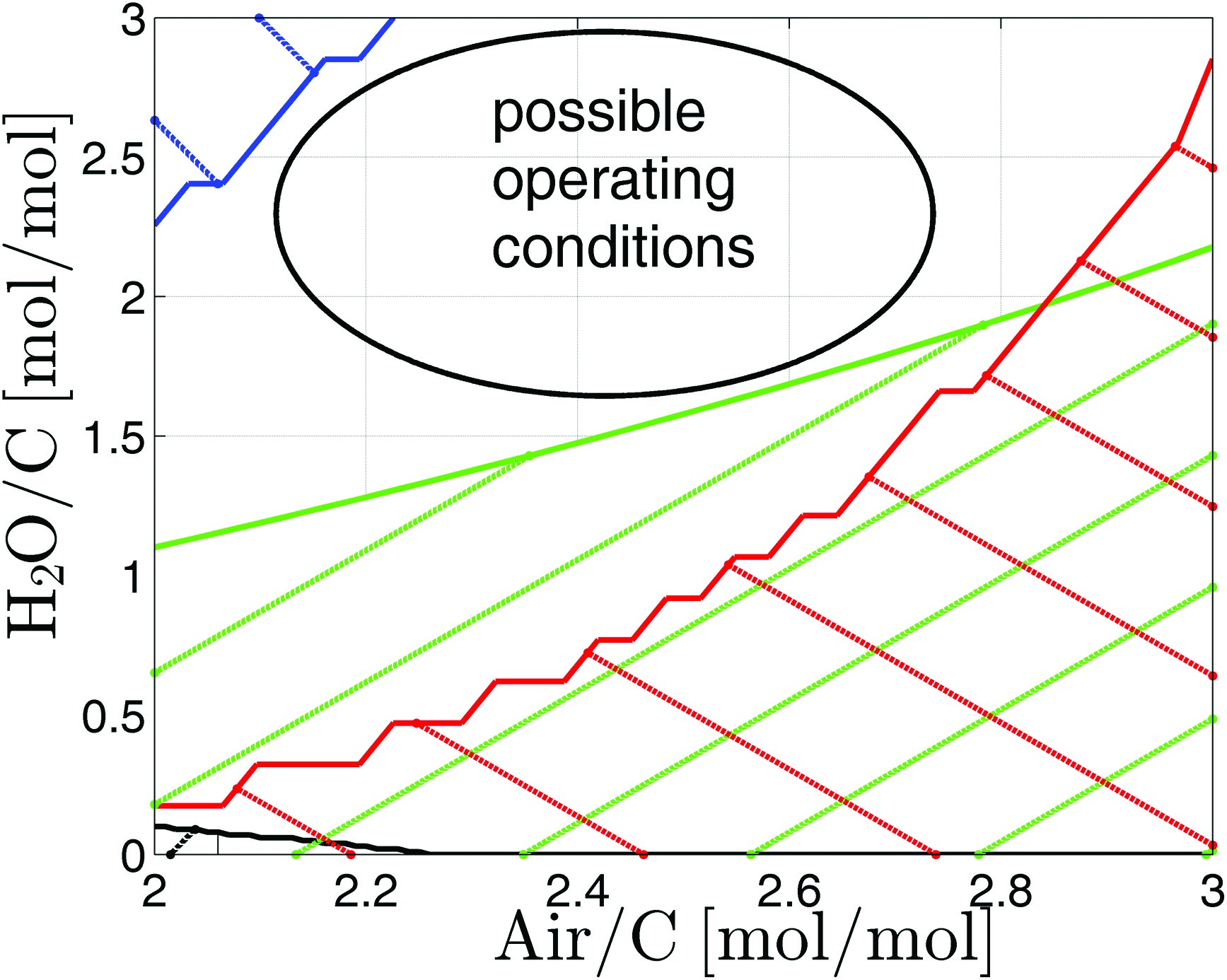
The four major constraints governing the operational window are illustrated in Figure 4. The operational window covers a stripe from Air/C ≃ 2.0 and H2O/C ≃ 1.75 to Air/C ≃ 2.75 and H2O/C ≃ 3. If the amount of air is increased too far, overheating occurs (red hatched area). By increasing the amount of water, deactivation becomes a problem (blue hatched area). Carbon formation seems to be of minor importance as the black area indicates. Only for mixtures with no or little water solid carbon is formed. In the black hatched area in Figure 4 the equilibrium carbon share is greater than 1 ppm. The green hatched area cannot be reached, because the ejector cannot generate the pressure gain required for operating the syngas generator. With an increasing amount of air, the load for the ejector also increases, as does the total mass flow through the syngas generator. Thus, the driving pressure rises and the ejector needs more water vapour to pump the air. Above a ratio of H2O/C ≃ 2.2 the pressure gain in the ejector is sufficient for all air mass flows considered.
Figure 4.
Operating Window: Blue: Low temperature deactivation; Red: High temperature deactivation; Black: Carbon formation; Green: Pressure constraint.
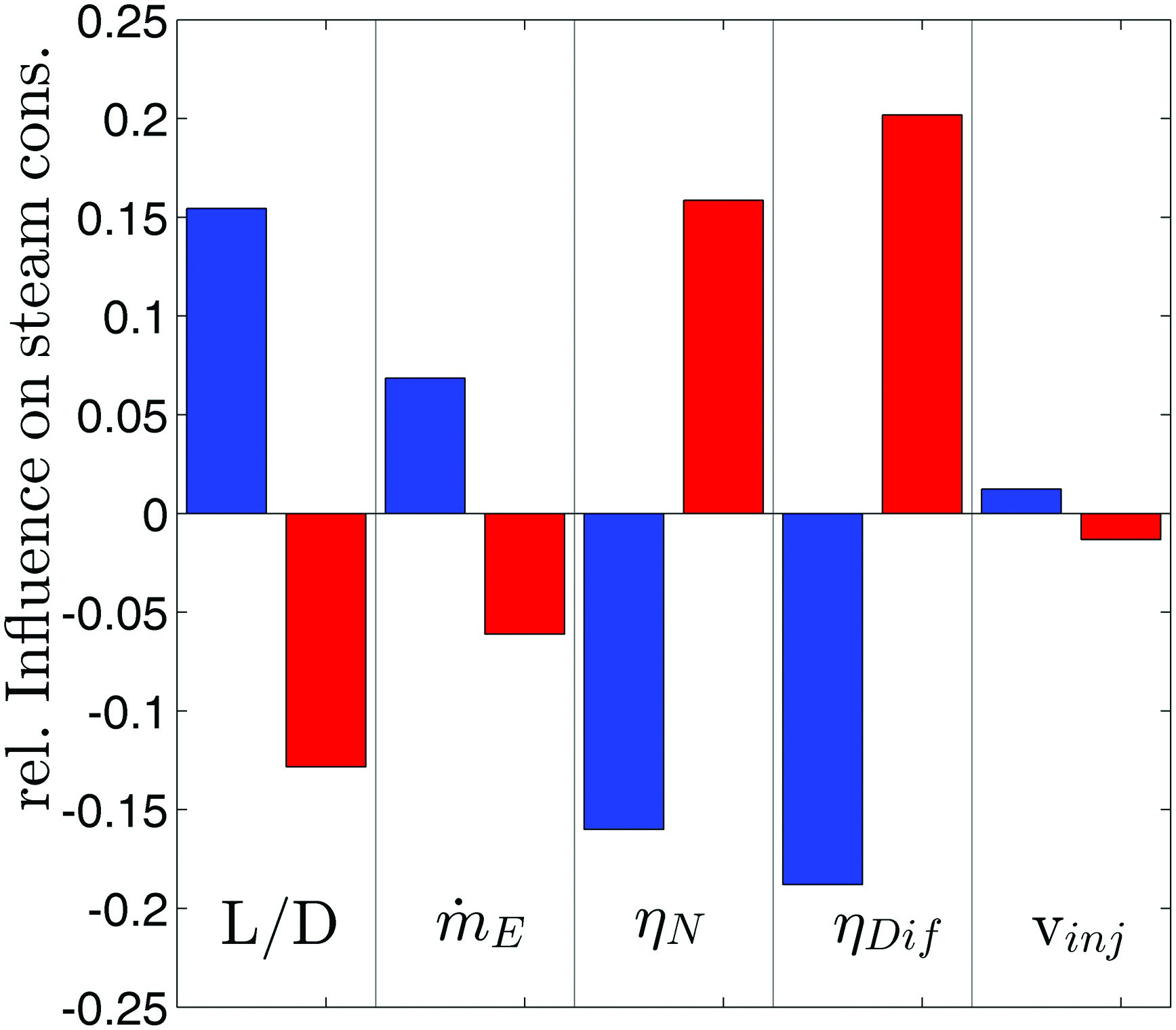
In addition, a sensitivity analysis has been performed. Several design parameters of the syngas generator affect either the pressure loss or the pressure gain in the ejector. Figure 5 shows the five most significant parameters governing steam consumption. Increased steam consumption moves the pressure boundary in Figure 4 (green) upwards and thus reduces the operational window. Due to the correlation of the effective velocity caused by the length-to-diameter ratio of the catalytic reactor L/D, it has a major influence on the pressure loss of the reformer. The mass flow of fuel to be reformed and the injection velocity of the syngas have significantly weaker effects. Increasing the fuel mass flow by 10% increases steam consumption by only 5%. The most influential parameters are the ejector nozzle and diffuser efficiencies. The most important outcome of the sensitivity study is the finding that proper ejector design is crucial to obtain the highest possible efficiencies and a wide operability range.
Kinetic study of the catalytic reactor
With the model of the catalytic reactor based on detailed chemistry the efficiency of syngas generation is calculated. Achieving a high hydrogen concentration in the produced syngas is essential because it governs the syngas reactivity. An important optimisation criterion is the minimisation of the residence time because it influences the size of the catalytic reactor and its pressure loss.
Description of the kinetic model
The fuel processor is calculated with two separate plug flow reactors (PFR), which are in series. Axial heat transfer is included in the model to account for the high thermal conductivity of the catalyst material. For the catalysts, surface reactions are accounted for and reactions in the gas phase are neglected. As temperature is relatively low, gas phase reactions are improbable. The kinetic model proposed in 18 is used for the first PFR, which simulates the noble metal catalyst used for ignition. It includes 10 surface species, 6 gas phase species and 36 surface reactions. This mechanism has been optimised to fit experimental data of the catalytic POX of methane without high water concentrations at the inlet. The mechanism was validated in the pressure range up to 10 bar with good results 18. A validated mechanism for pressures up to 20 bar for catalytic POX does not exist, to the best of the author’s knowledge. Inert nitrogen is added to the gas phase mechanism by the authors of this study because this species was not part of the original mechanism. The reaction scheme for the nickel catalyst is adopted from 14. It has been designed for steam reforming on nickel catalysts. The mechanism involves 13 surface species, 8 gas phase species, and 43 surface reactions.
Results of the kinetic study
For the reactor analysis in the current context, Air/C = 2.5 mol·mol-1 and H2O/C = 2.5 mol·mol-1 has been selected, which represents an operating point inside the operating window identified above. The other settings such as size of the fuel reformer, mass flow to be reformed and so forth are the same as those modelled before, see . A heat loss of 10% of the converted higher heating value is introduced to account for the heat losses of the syngas generator. This value fits best to measurements on a syngas generator test rig, which will be published subsequently. The results of the calculation at 20 bar are depicted in Figure 6 and in Figure 7.
Figure 7.
Calculated gas temperature: 0–20 ms noble metal catalyst for ignition, 20–225 ms reforming catalyst.
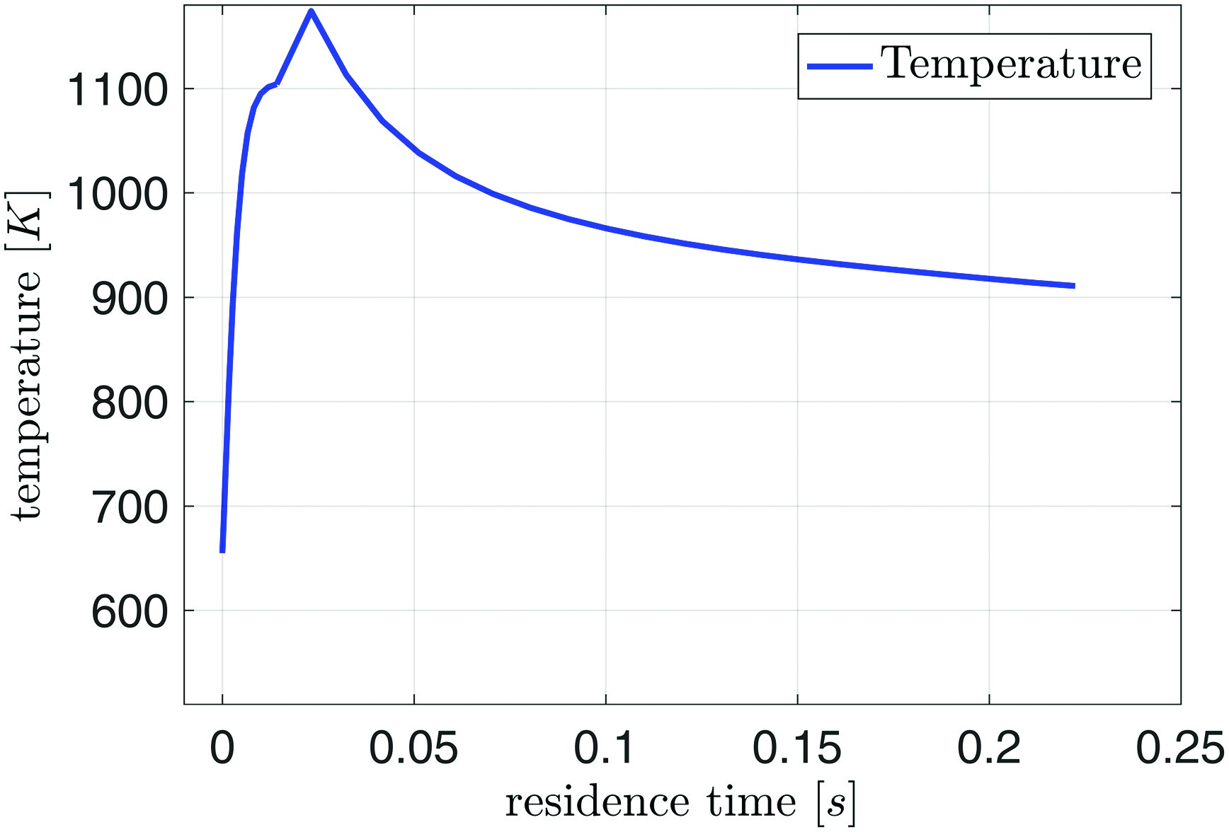
Figure 6.
Calculated species mole fractions: 0–20 ms noble catalyst for ignition, 20–225 ms reforming catalyst.
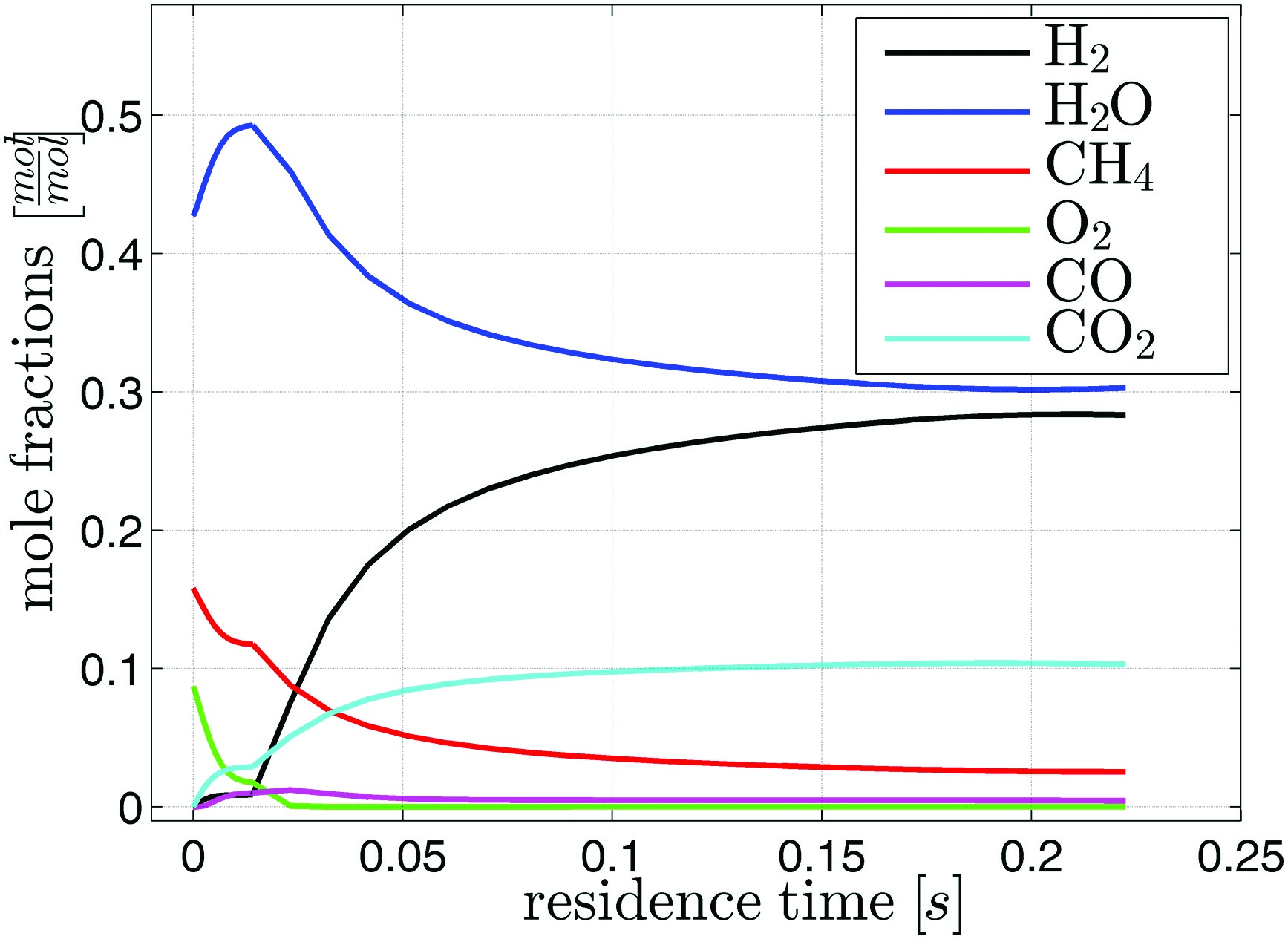
In the investigated case, combustible gas has a residence time of 20 ms in the ignition catalyst. After ignition, oxygen and methane are consumed while water and carbon dioxide are produced. Only very little hydrogen and carbon monoxide are created. A significant temperature rise from 650 K to 1,100 K is calculated. Reforming occurs in the second catalyst stage. Here mainly water and methane are consumed to produce hydrogen and carbon dioxide. The vast amount of water in the mixture suppresses the production of carbon monoxide via the shift reaction. As the reactions in the reforming stage are endothermic the temperature drops to 910 K The sudden increase in temperature at the entrance of the second stage does not happen in reality. Apparently, the reaction mechanism is not designed to cope with oxygen in the reactants. The activity is overestimated. However the calculated methane conversion of 80% within the given residence time is in line with data from literature 15. The final composition of the mixture is approx. 30%-vol water, 30%-vol hydrogen, 30%-vol nitrogen, 10%-vol carbon dioxide, and a few percent of methane. The syngas contains hardly any oxygen or carbon monoxide. For other ratios of water and air to fuel inside the operating window, the general trends for the syngas composition and temperature are similar.
Calculation of the laminar burning velocity
The one-dimensional laminar burning velocity of the syngas and methane mixture has been calculated to evaluate the effect of syngas addition on combustion stability. The calculation was performed with the GRI3.0 mechanism 23, which has been designed for methane. Since it incorporates hydrogen and carbon monoxide mechanisms, it can also be applied to syngas and syngas/methane mixtures. In the subsequently presented cases, the air temperature is 673 K, the methane is assumed to have a temperature of 300 K, and the syngas temperature is 910 K, according to the results of the kinetic model presented in the last section. The total pressure is held constant at 20 bar.
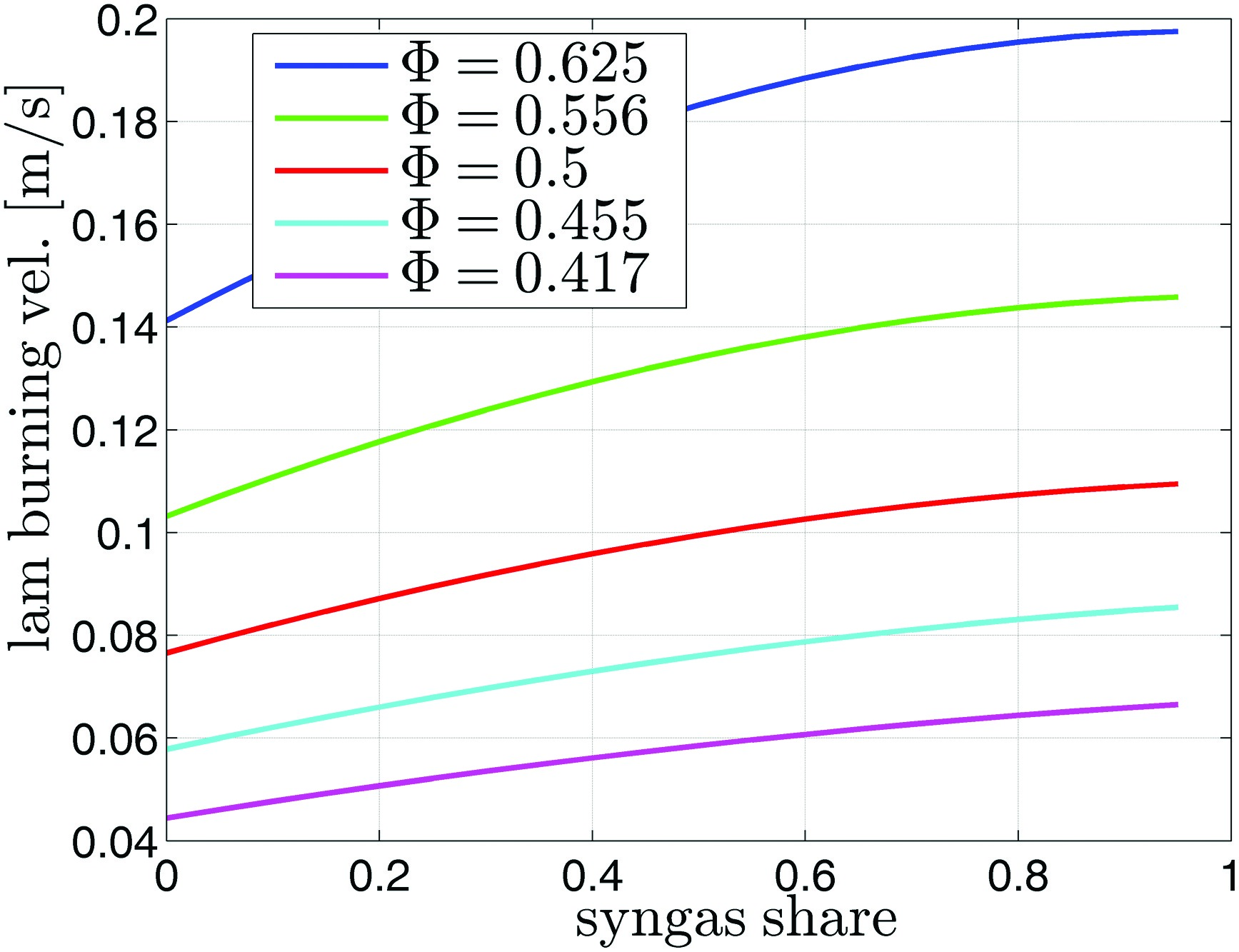
Two different sets of calculations were performed. In the first case the laminar burning velocities for mixtures with an increasing share of syngas at constant equivalence ratio was calculated. The syngas share corresponds to the amount of natural gas that is reformed. A non-stretched free flame was implemented to first calculate the methane flame with different equivalence ratios. Then the share of syngas in the fuel was increased at constant equivalence ratio and the laminar burning velocity of the mixture was determined. The results of this calculation are shown in Figure 8. With an increasing syngas share, the laminar burning velocities are increasing. For the ϕ = 0.5-case pure methane has a laminar burning velocity of 7.6 cm·s-1, which is increased by a substitution with 50% syngas to 10 cm·s-1, an increase of 32%.
Figure 8.
Unstretched one-dimensional laminar burning velocity of syngas and methane mixtures calculated with the GRI3.0 mechanism 23.
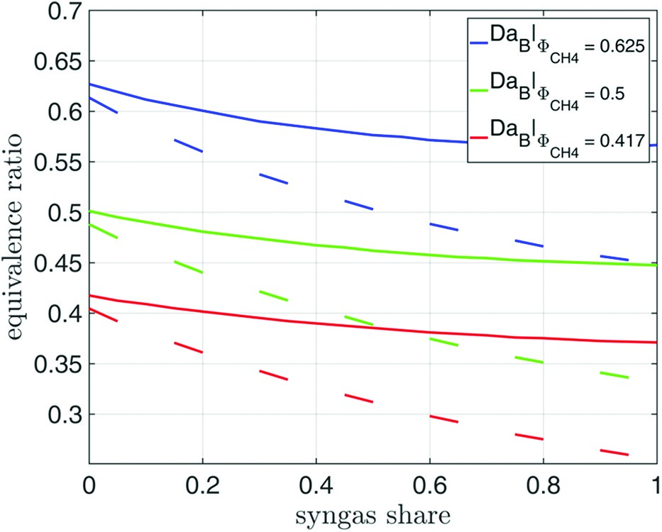
In the second case, the goal of the computations was to find the equivalence ratio of syngas/methane mixtures, which exhibits the same Damköhler number DaB as that of methane. Correlations for the LBO equivalence ratio based on a Damköhler number, defined as
As can be seen in Figure 9, the equivalence ratio at constant DaB is reduced significantly with rising syngas concentration in the fuel. The dashed lines correspond to the equivalence ratio corrected with the term for the preferential diffusion effect. Comparing the pure methane ϕ = 0.5-case with an injection of 100% syngas, the same DaB is reached with a corrected equivalence ratio of ϕ = 0.33. According to the considered generic gas turbine, the total natural gas mass flow for part load is 11.9 kg/s, assuming a reduced air intake to 70% of full load intake and an equivalence ratio ϕCH4 = 0.5. On the other hand, the total natural gas mass flow that exhibits after conversion to syngas the same Damköhler number is only 9.4 kg/s. This corresponds to a decrease in thermal power of 20%. The detailed derivation is shown in .
Conclusion
The goal of the presented study was the analysis of the feasibility of an autothermal on-board syngas generator for improvement of the turn-down ratio of gas turbine combustors in unstaged operation.
Modelling reveals that an ejector pump driven by the steam produced in the HRSG can overcome the pressure loss induced by the catalytic reactor and the subsequent syngas injector in the burner. The temperature of the catalyst bed can be controlled by adjusting the Air/C and the Water/C ratios. An increasing amount of water reduces the temperature while more air results in rising temperature. Overheating and deactivation of the catalyst can be avoided by adjusting the mixture entering the catalyst bed. Carbon formation has been identified to be of minor threat for the catalyst. The analytic model shows that a wide operating window for the syngas generator exists.
Employing a sensitivity analysis, the length-to-width ratio of the fuel processor, the efficiency of the ejector nozzle, and the efficiency of the ejector diffuser have been identified as important design parameters. These parameters have a great influence on the pressure loss of the catalyst or the pressure rise in the ejector, respectively.
PFR type calculation with detailed chemistry reveal the general behaviour of the fuel processor. The resulting syngas has a hydrogen volume fraction of 30% and a temperature of 910 K. Calculations of the laminar burning velocity show a significant increase when substituting methane by syngas. This is also reflected by the calculation of the equivalence ratio for constant Damköhler numbers. A decrease of up to 20% of thermal power seems to be possible by reforming the fuel without increase of flame length or sudden blow-out.
The present study shows the feasibility of ATR for on-board syngas generation. The higher reactivity of syngas allows to improve the turn down ratio of gas turbine combustors in unstaged operation. Experimental data are only used to quantify the constants in and the heat loss in the kinetic model. As further steps, the conversion predicted by the kinetic model employed in the present study will be validated by experiments with a lab scale syngas generator, and the predictions of the operation range extension will be verified using the combination of the syngas generator and a premix burner equipped with injectors for syngas/methane mixtures.
Appendices
Appendix A.
Appendix A. Model parameters for the gas turbine and the reformer.
Table 1.
Appendix B.
Appendix B. Decrease of thermal power by autothermal reforming.
Mass flow of methane in part load regime (IGV, fuel reduction):
Mass flow of syngas to the reformer in part load regime (IGV, fuel reduction):
With the corresponding air mass flow:
The stoichiometric air to syngas mass flow:
This leads to a natural gas mass flow to be reformed:
The decrease in thermal power is thus: