
Introduction
The development of additive manufacturing technologies unveils a new level of opportunities for aerodynamic and mechanical optimization of gas turbine engine elements for higher efficiency, reliability and specific parameters. The presented research aims to investigate the impact of partial infill of the inner blade space on the natural frequencies of compressor blades. The inner space can be filled with either solid uniform material or with more complicated lattice structures. The latter can be divided into uniform simplified structures like square or square-shaped two-dimensional extrusions or lattices of variable density.
Additively manufactured blades with lattice infill for improved mechanical properties have been widely studied and reported in the literature. Cheng et al. (2017) manufactured a series of components with partial infill of the inner volume with lattice structures. The main objective was the reduction in weight while maintaining the outer geometrical shape and structural properties such as natural frequencies and stress limits. Another example of inner volume optimisation was shown by Seppälä and Hupfer (2014) optimised turbine guide vanes with limitations to blade natural frequencies and deformations. Outer surfaces remain untouched and the whole inner space with respect to the wall thickness was fully explored during the optimisation. Potential 19% improvement was shown, yet with higher thermal stresses at transient conditions.
Moneta et al. (2022) used internal cavities for storing the unmelted powder. This improved damping via dissipation of the vibration energy between internal structural elements and metal powder. Barreau et al. (2022) optimised internal topology of the blade for reducing the number of resonant frequencies in the working range of the blade together with blade enforcement for bird strikes. He achieved a 15% mass reduction together with a lower centre of gravity to reduce centrifugal loads.
Additively manufactured materials were also used to create morphing or flexible structures. Wu et al. (2016) proposes active trailing edge of the aerofoil with sufficient stiffness yet smooth surface. Another use of such materials can be in utilization of complex lattice structures to increase beam stiffness under compression loads, like in (Dal Fabbro et al. 2021), or to increase energy absorption by the structure like in (Bari 2023; Zhang 2023).
Vlădulescu and Constantinescu (2020) performed a topology optimisation of the robotic arm bracket with a cubic cell lattice structure. They used the analysis system “Direct Optimization” in ANSYS Workbench. The authors also used cubic lattice structures for natural frequency optimisation and achieved a 50% gain in frequency with 50% mass savings.
The review of the aforementioned publications shows that many authors aim for complex shapes and sophisticated configurations while avoiding basic low-order considerations. This is done in a push for even more mass savings and structural gains. Simpler ways of blade enforcement with solid or hollow elements are rarely discussed in the literature. As a result, the improvement brought by complicated topologies cannot be clearly seen. To oppose this trend the presented paper aims to show how partial homogeneous infill or simplified structures can be used to change the natural frequencies of the blade. The simplified structures are studied for two reasons:
Limited space inside the blade does not always allow for more complicated solutions. The complexity of infill structures is limited by the resolution capabilities of additive technology. For selective laser melting (SLM) the layer thickness is between 0.03 and 0.15 mm. At the same time, for axial compressor blades especially in small gas turbine engines the distance between the two blade walls where the partial infill can be applied is in order of 0.5–3 mm. Therefore, only simple two-dimensional structures can be feasible, and this paper aims to quantify possible improvements in such cases.
Sometimes, the role of complex lattice structures with variable density is overestimated and most of the improvements in weight savings and rigidity can be achieved with simpler structures. Therefore this paper aims to give a benchmark of such improvements with simpler structures so that when more complicated approaches are used, they can be referenced to the simpler ones of this paper instead of referring to solid body.
This paper first considers a flat hollow plate as a universal example understandable by a wider audience to explore the limits of weight savings and natural frequency gains. The plate has proportions representative of the turbo-fan blade; however, similar structural elements are widespread in engineering practice, and the research can be useful for many future designs. At the same time, the simplified cases allow the reader to see clear connections with intuitive physical expectations of a structural engineer and therefore the design decisions can be embedded into the design process. In the second part of the paper, the representative rotor blade of an axial compressor is discussed.
Methodology
Geometrical setup
The geometry of the flat plate is illustrated in Figure 1. The parameters are taken from a representative rotor blade of a high-pressure axial compressor of a gas turbine engine with the ratio of length to width (the Aspect Ratio) of 2. Unlike the blade, the thickness of the plate is uniform across it in both directions. When allowing infill of the inner space, the plate essentially becomes a thin-walled box, and the inner volume of this box is the research object of this paper. The bottom side of the box has a fixed support boundary condition. The rest of the surfaces have no restrictions applied, and all the walls together are made as a single solid body.
The thickness of the plate is 6 mm and the wall thickness for all configurations is 1 mm, therefore the inner space represents 67% of the plate thickness and nearly the whole length and width. The blade on the left of Figure 1 is used in the second part of the paper. It has an identical proportion of the wall thickness related to the depth of the inner space for infill at a point of maximum profile thickness.
Figure 2 shows the deformations of the flat plate when vibrating and its resonance frequencies. Figure 2a shows the cantilevered beam vibrating at first bending mode. As known, the natural frequency of a beam is a function of its stiffness and an inverse function of its mass. It is also known that the stiffness of the beam is more important at a place of minimum deformations – near the fixed-point, whereas the mass is more critical at the free end of the beam. The two parameters and their locations of importance are sketched in Figure 2a. Figure 2c–d shows the first three vibration modes of the flat plate: first bending mode (B), first torsional mode (C) and second bending mode (D). For compressor blades, the modes are more complicated than for the flat plate, and the deformations would be of a mixed kind. Depending on the configuration, the first mode of the blade can be primarily bending or torsional. For the blade of interest, the former is the case.
Homogeneous infill
As a simplified example, a homogeneous infill type is used first in the paper, shown in Figure 3a. The filler originates from the bottom - where the fixed support is applied. This is to address the basic physical principle: the stiffness in this case is critical near the support - in a region of peak stresses, and the mass is critical in the region of highest deformations.
The one-dimensional infill is shown in Figure 3a where only the height of the filling part is varied, and the width and the thickness are uniform. Figure 3b shows the non-uniform filler along the width: in this case, there are 10 columns filled vertically. The columns are symmetrical across the middle line of the plate so only five bars on the left-hand side were controlled and the other five on the right-hand side were obtained by reflection.
Lattice infill
A two-dimensional square-shaped structure (Figure 4) was used for this study as it allows for rapid design within complex blade geometries as well as robust geometry generation and meshing. The structures have a square cross-section and are uniform along the thickness of the blade. The walls have a constant thickness for all the options studied and are equal to the wall thickness of the plate. In Figure 4 several options are shown along the increasing filling ratio of the inner space. The percentage of volumetric infill shown as the horizontal axis in Figure 4 is calculated based on the cross-sectional area of the lattice. This is true for the flat plate and to some extent correct for the compressor blade of interest.
Computational setup
Industry-standard FEM setup was used for frequency calculations. The plate has a fixed support boundary at the bottom surface. The blade is fixed at two root surfaces as it would be during operation. No slip or elasticity conditions were included.
For the geometry configuration shown in Figure 3b a set of optimisation problems has been formed. The five columns were varied in height in an optimisation loop to achieve the highest possible natural frequency at one of the three modes. The weight of the model is not considered for the optimisation. Although the two-dimensional optimisation did provide a sensible Pareto front which has shown further mass savings with little compromise in frequencies, the low-order effect can be clearly seen even when just maximising frequency alone. This is because the mass reduction at the top of the plate, which ensures major improvement for frequency, is beneficial both for higher frequency and lower mass.
Flat plate study
Homogeneous one-dimensional infill
To understand the effect of the infill on plate natural frequencies, this section considers a linear homogeneous filling starting from the bottom end of the plate (Figure 5). The first natural frequency of the solid plate (100% infill on the vertical axis) is 499 Hz. All other modes for first three modes are given in Table 1 in percentage of the solid plate. The empty box (0% infill) has a higher first mode frequency of 591 Hz (18%) and mass reduction of 61%. However, the change in the frequency between the two extreme cases is not straight - there is an extremum at nearly 50% meaning that a half-filled hollow plate can have 45% higher first-mode natural frequency than the solid plate (726 Hz) and at the same time have 31% less weight. This 31% weight reduction can be sufficient to compensate for cyclic load stress limits which are normally lower for the 3D printed materials.
Figure 5.
A flat plate with solid linear infill of variable height (left) and first three natural frequencies of the flat plate together with mass reduction.
Table 1.
Optimisation results of a flat plate with one- and two-dimensional homogeneous infill (in percentage to solid flat plate).
The change in frequency in Table 1 is calculated according to:
where i = 1, 2, 3 – mode numbers. A similar formula was used for mass reduction calculations.
Homogeneous two-dimensional infill
Figure 6 shows the simulations for the topology from Figure 3b. The two-dimensional optimisation is performed with variable distribution of the material along the width. For each of the three vibration modes, a separate optimisation routine was run with the ultimate goal of the highest possible frequency for the mode of interest.
Figure 6.
Deformation contours and two-dimensional solid infill layout of the flat plate optimised for highest possible natural frequencies at first three modes.
Figure 6a shows the optimised version for the first mode. The resultant frequency is 47% higher than for the solid plate with a 35% weight reduction. This is somehow more advanced compared to 45% and 31% respectively for the 50% infill case in Figure 5. The main reason for the results to be similar is that the solid one-dimensional infill coincides with the first bending mode of the plate.
For the first torsional mode, the improvement is significant: 35% gain in frequency and 32% reduction in mass compared to 25% and 26% respectively. Figure 6b shows that mainly the central bars were extended for nearly 80% of the height with the sidebars being shorter than that for first bending mode optimization.
The second bending mode (mode-3) has shown a 20% gain in frequency compared to 5% for one-dimensional infill with a mass reduction of 40% compared to 12%. As a matter of interest, there was an attempt to populate infill bars from the second nodal diameter to directly capture the stiffness of the plate at the second bending mode. The results of this are shown in Table 1 as “second-mode enforcement”. However, it did not show any marginal improvements for this mode and also significantly worsened the performance of the other two modes.
To conclude, the two-dimensional setup allows for better resolution of the stiffness/mass approach and therefore allows for higher frequency gains. The colours in Figure 6 represent total deformation on the plate surface and the dark blue region of the lowest deformation coincides with the filling pattern.
Lattice structure
As was shown in Figure 4, the square-shaped structures were varied in size and as a result provided linear increment in infill ratio when the structures were evenly spaced along the plate's height. Figure 7 shows the change in the first three natural frequencies and the weight savings along the infill rate for different widths of the squares.
Figure 7.
First three natural frequencies of the flat plate and mass reduction for variable infill density of uniformly-distributed square-shaped lattice structures.
With increasing infill ratio the plate gains rigidity but at also gains weight at its free end. Therefore for all three vibration modes, the highest gain in frequencies is seen at low infill, where, according to Figure 4, between two and five squares are fitted within the width of the plate.
The highest gains in frequencies are 26, 17 and 15% for the three modes respectively which is lower than the improvements of linear infills shown in Table 1, however, the weight reduction is up to 60%, and for the case of four squares in the row (encircled in dashed line in Figure 7) the reduction is 55% which is a substantial improvement.
The next step is to vary the height of the square-shaped structure along the height of the plate with the optimum at four squares per row as shown in Figure 8. Compared with full-length infill there could still be a slight gain of 3–5% in the first two modes with mainly negative change for the third mode. The mass reduction is varied between 54 and 63% and either value would still be a significant improvement for the real blade.
Compressor blade study
When the actual compressor blade is optimized, there are two geometrical features which limit possible improvements in the frequencies. First, real blades have thicker sections at the root and thinner at the tip. This is done to account for centrifugal loads so that at the tip the section area is the lowest for reduced mass, and at the root the area is the highest for reduced stresses. Second, the blade has variable thickness along the chord, and such a shape already provides higher stiffness at mid-chord and lower mass at the ends which is beneficial for torsional modes. These two factors evolved historically, and they make blades already better designed for higher natural frequencies than the flat plate. So, the improvement from using partial infill is limited.
Figure 6 is a good example of how the natural frequencies can be optimized with homogeneous infill by placing the material at the regions of lowest deformation. In this section similar approach will be applied to the blade. First, it is done with solid infill and then – with a square-shaped lattice structure.
Homogeneous infill
Originally, solid homogeneous infill was tried uniformly along the blade chord in the same way as in Figure 5. For this the highest results were obtained at 60% infill compared to 50% for the flat plate and the improvement in frequencies is half of that for the plate. However, even for the blade case, 26% gain in first mode was achieved. These results are reflected in Table 2, and the results have similar logic to Table 1.
Table 2.
Blade Optimisation results with homogeneous uniform and deformation-shaped infills.
For a complex shape of the blade, the linear infill can have limited potential for frequency optimisation, and the physical intuition for the designer is less clear. To address that challenge a deformation-shaped infill procedure was proposed which consists of two steps. First, deformation contours of a solid blade are calculated and second, the infill pattern is shaped according to these contours (see Figure 9 for reference).
Figure 9.
Deformation contours of the compressor blade (left) and natural frequencies (right) with solid partial infill which is shaped according to the deformation contours for the first bending mode (top) and the first torsional (bottom).
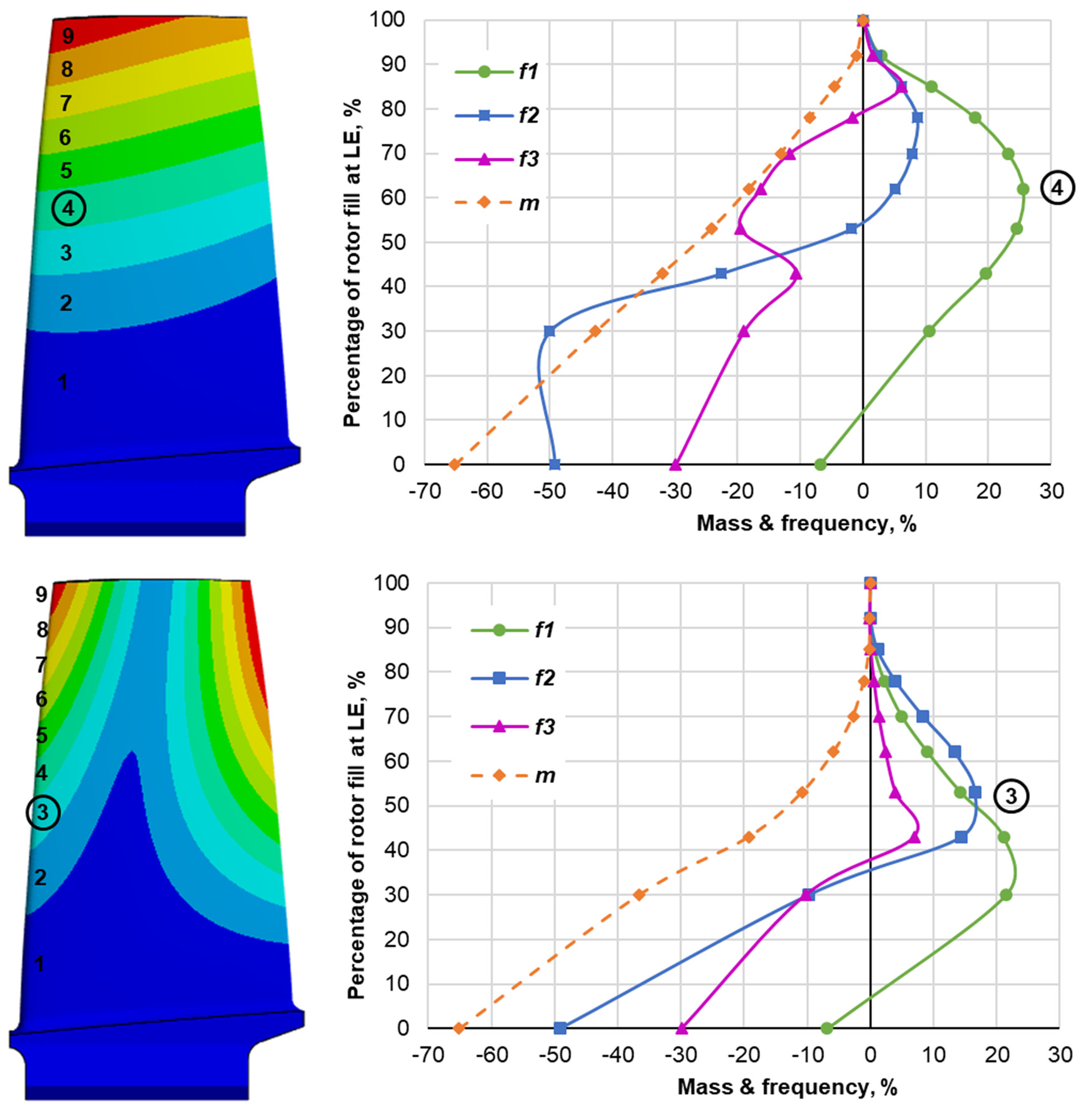
Left two plots in Figure 9 show the deformation contours of the blade with first bending (top) and first torsional (bottom) frequencies. Ten contours are drawn at each plot and each contour is numbered along the leading edge of the blade. On the right-hand side of this figure the graphs show changes in natural frequencies and mass for the blade where the solid infill is shaped according to one of the contours on the left. The vertical axis of the right-side plots is the percentage of infill height at the leading edge. For the contour with the highest gain in bending and torsional frequencies the numbers are circled.
For the bending mode contours the highest gain in first natural frequency can be seen for contour 4 which roughly corresponds to 60% of the blade height and the contour has nearly uniform height along the blade chord. The first mode frequency grew by 26%, and others changed by 6 and −20% respectively. According to Table 2, 1D homogeneous infill has identical results. Filling with contours 3 and below resulted in a drastic drop in torsional mode accompanied by negligible benefit for the first bending one.
Contoured infill based on contour 3 of the torsional mode deformations (bottom of Figure 9) has shown the gain in the first torsional mode by 16% which is less than half of that for a flat plate. The first and second bending modes are higher by 14 and 4% respectively. The mass reduction in this case is only 10% compared to 27% for a flat plate.
Overall, deformation contour infill allows designers to tune the blade frequencies out based on a given Campbell diagram in the real engine. With that comparatively simple infill patterns the room for change reaches 10–30% of the frequencies as well as 10–20% mass reduction opportunities.
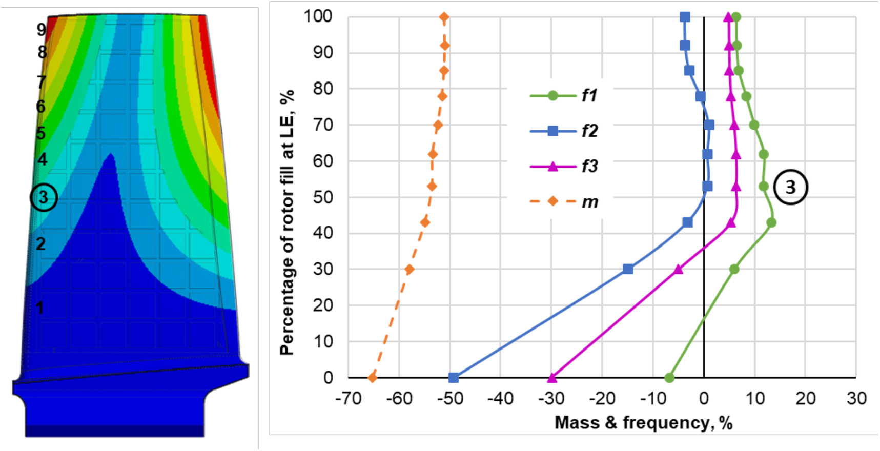
Lattice structure
Figure 10 shows the contour-shaped partial infill with the simple lattice structure. Both bending modes have improvements at a level of 5–10% and the torsional mode has negligible change for all the contours apart from the bottom three. However, the weight reduction is comparable to that of the flat plate due to the identical topology of the structures: 50–70%. Therefore, blade infill optimisation can be performed by the blade designer by varying the square width and implementing it for contoured infill of Figure 9. This part is omitted from the paper, as the results can be anticipated.
Results and discussion
The paper discusses the impact of partial infill structures on the first three natural frequencies of a flat plate and representative compressor blade. For the plate improvements in frequency can be as high as 47%, 35% and 22% for the first three blade modes. At the same time, the mass savings were shown to be up to 27–39%. When square-shaped lattice structures were used the improvement was 32%, 19% and 15% for the frequencies and up to 57% for the mass.
For a representative compressor blade with homogeneous infill shaped according to blade deformations the improvements were shown to be 26%, 17% and 6% respectively with mass savings of up to 18%. When lattice structures were used, the improvements were 12%, 1% and 6% for the frequencies and 52–55% for the mass.
When optimisation results can be anticipated for a given blade, the next question is how to apply the findings in engineering practice. A basic option would be to reduce the weight of the part, which, for a gas turbine engine can lead to a lighter engine and therefore lower fuel consumption of the plane. Although the weight contribution of the blades to the whole engine is within a few percent, further weight savings in rotor discs can add to it. Also, additively manufactured components are known to have reduced high-cycle fatigue and blade mass reduction allows to maintain overall blade life span.
Another option is to reduce the thickness of the blade and therefore reduce the aerodynamic losses while maintaining the stresses and natural frequencies of the blades at a similar level with datum blades. The calculation has shown that for the same first bending mode frequency of the flat plate its thickness can be reduced by 20% when partial infill is used. To maintain the first twist mode the blade can be 13% thinner. These calculations were done for homogeneous filling of the inner space.
Conclusions
Additive manufacturing technologies can only be superior when their potential is fully explored both in structural and functional ways. This paper quantified the potential improvement in natural frequencies and weight of the flat plate and typical axial compressor blade when partially filled with homogeneous and simple lattice structures.
This paper has also demonstrated how such structures can be used to control natural frequencies. The key principles for designing such blades were shown. The resulting infill shapes agree with fundamental physical understanding, for example, the filling density is maximum in regions where maximum stiffness is needed, and it is minimum in the region of highest deformations.
As a result, a simplified method of partial infill has been developed based on deformation shapes of the solid blade. This method can be easily applied by turbomachinery designers in their practice.
Simple infill structures can be used in such blades where more complicated three-dimensional structures are not technologically feasible. Even when the blades do have more space for complex infill, the simple infill patterns are still important as they can provide a good benchmark for other methods to be applied.