
Introduction
Heavy-duty road transport produces approximately 5% of the European Union's total greenhouse gas emissions, contributing more than international shipping and aviation to the total CO2 release in the atmosphere (European Commission, Climate Action, 2017). Many organizations around the planet are investigating potential mitigation strategies, which arguably feature two main trends. The first one focuses on the improvement of the components in conventional reciprocating engines, e.g., design optimization of pistons for higher compression ratios (Gibble and Amar, 2016). The second trend instead aims at the electric hybridization of the power train. This configuration makes it possible to downsize the combustion engine, to recover energy during deceleration, to continuously operate the engine under optimal conditions, and to eliminate idle fuel consumption and clutching losses (Guzzella and Sciarretta, 2013). A hybrid electric power train is particularly suited for long-haul trucks (class 8, weight >15 ton) and buses. These trucks travel for long distances, their current autonomy range cannot arguably be reached by means of a fully electric power train without significant payload penalties, due to the insufficient energy density of current and near-future electric batteries (Aharon and Kuperman, 2011). Furthermore, these vehicles operate in stable cruise conditions for many hours, hence the power plant and its control can be optimized for constant on-design operation allowing for higher efficiency and lower emissions. Several companies have been and are developing heavy-duty hybrid power trains with prime movers like reciprocating engines (Daimler Trucks North America LLC, 2017), fuel cells (Goodarzi, 2017), and micro gas turbines (Wrightspeed Powertrains, 2017).
The use of a gas turbine for road propulsion provides several potential merits: high power density, fuel flexibility, ultra-low emissions, low vibrations and noise, simplicity and lower maintenance cost. This concept was already studied decades ago. Even though commercial organizations realized prototypes of heavy-duty trucks and passenger cars, gas turbine powered vehicles were not introduced into the market, mainly due to the poor efficiency of micro/mini gas turbines, especially in off-design conditions (Chrysler Corporation: Technical Information Engineering office, 1979). This problem does not occur if the gas turbine is part of a hybrid system, because the machine can always run at optimal conditions independently from the vehicle speed and gear position. By employing a bottoming organic Rankine cycle (ORC) system, it is possible to increase the efficiency of micro gas turbines (μGT, power output <500 kW) to at least 40% (Invernizzi et al., 2007). Moreover, recovering waste energy from a single high-temperature source, the exhaust of a µGT, is easier than recovering heat from a Diesel engine, for which the full recovery potential can only be achieved if also the low-temperature energy content of the cooling and lubrication system is employed.
This paper showcases the analysis of a hybrid power train for a class 8 truck employing a combined cycle with a µGT and a mini ORC system (mORC, power output <50 kW) as the prime mover. In this explorative investigation, the design of the ORC system components follow procedures corresponding to current and commercial technology levels. The results of this work are therefore conservative.
The assessment of the proposed power train concept was developed in two steps. The first step deals with the preliminary design of the combined cycle (CC) power plant, while the second focuses on the evaluation of the vehicle fuel economy over a representative mission. During the preliminary design phase, recuperative and non-recuperative cycle configurations were studied, and the working fluids for the mORC were selected by taking into account performance, manufacturing constraints typical of small scale turbomachinery, safety and environmental aspects. The design of the heat exchangers was performed with a well-known engineering software (Aspen Technology, Inc., 2015), and by taking into account constraints on weight and volume given by the vehicle architecture. The estimated characteristics of the CC gen-set are then used for the assessment of the fuel economy of a hybrid electric long-haul truck at full load (approx. 36 ton of weight); this analysis is performed with an open source library for quasi-steady-state simulations of road transport driving cycles (Guzzella and Ambühl, 2005). A series configuration with Lithium-Ion batteries was selected for the hybrid powertrain, because it decouples the prime mover dynamics from that of the vehicle (Guzzella and Sciarretta, 2013).
The objective of the analysis is to evaluate the trade-off between the size of the batteries and the cargo weight and fuel economy, and also to estimate the flue gas emissions if natural gas is employed.
Methodology
The preliminary design of the CC system has been carried out by means of a computer code developed with a general-purpose open source programming language (Python Software Foundation, 2017), while the evaluation of the fuel performance over selected driving cycles has been performed with an open-source library (QSS-Toolbox) (Guzzella and Ambühl, 2005), for use with a graphical programming environment for modeling, simulating and analyzing multidomain dynamical systems (The Mathworks, Inc., 2017). The estimation of fluid thermophysical properties needed for the thermodynamic cycle analysis of the considered CC systems are obtained by means of well-known fluid property libraries (Colonna et al., 2019; Bell et al., 2014).
Preliminary design of the combined cycle
Figure 1 displays the three simplified schemes of the studied cycle configurations. The configuration of Figure 1a, named RGT-ORC, is based on a state-of-the-art μGT turbine operating with a low pressure ratio of four, a maximum turbine inlet temperature approaching 1000°C, and a gas-to-gas recuperator with a maximum inlet temperature of approximately 650°C (Visser et al., 2011). Regarding the ORC system, a preliminary thermodynamic analysis showed that regeneration has little effect on the overall efficiency; the ORC regenerator is thus omitted. Additionally, the water in the flue gas might partially condense in the primary heat exchanger of the ORC unit. This phenomenon has been modeled following the procedure reported by Lu et al. (1987).
Figure 1.
Process flow diagrams of the studied combined cycle systems. (a) RGT-ORC, (b) GT-RORC, (c) GT-RLORC.

The CC power plant configuration in Figure 1b is based on a non-recuperative gas turbine (GT-RORC). In this case, if a high thermodynamic efficiency is sought for, the turbine inlet temperature is to be raised at levels beyond those attainable by uncooled blades. An alternative is to employ a ceramic turbine, and this technology was demonstrated in the past with a TIT as high as 1350°C (McDonald and Rodgers, 2008). The potential of this technology is still under scrutiny, as shown by recent research projects on micro ceramic gas turbines for unmanned air vehicles (Vick et al., 2016). For this cycle configuration, the preliminary thermodynamic analysis showed that the best performance is achieved with a regenerator in the waste heat recovery system.
Figure 1c shows the third considered configuration (GT- RLORC), a non-recuperative gas turbine with a bottoming cycle employing an additional (low temperature) heat recovery exchanger (LTHRE). In this case, the liquid flow leaving the ORC pump is split, in order to obtain an optimal match between the temperature profiles of the hot and cold stream in the regenerator. The bypassed liquid flow is then preheated by the exhaust gases after exiting the high-temperature heat recovery exchanger (HTHRE), thus increasing the amount of thermal energy that is utilized. Also this system requires a high gas turbine inlet temperature, in order to reach a high conversion efficiency. Here, instead of a ceramic turbine, film blade cooling is considered (Taguchi et al., 2017). It could be then possible to raise the turbine inlet temperature to values as high as 1500°C (like in modern stationary gas turbines or aero engines). The impact of film cooling on the thermodynamic cycle efficiency is taken into account by following the work of Horlock (2003), and assuming a four stage machine with cooling at the inlet of the first two stages.
A thermodynamic cycle analysis is used to determine the optimal cycle specifications, which are then used to design the turbomachinery and the heat exchangers. The procedure can be consulted in any engineering Thermodynamics textbook, see, e.g., Reynolds and Colonna (2018); thus, it is not reported here. A degree of freedom of these CC configurations is the ORC condensing temperature. Its value is determined following the calculation procedure described in the following section.
Determination of the ORC condensing temperature
The geometry of the ORC condenser is assumed of the plate-fin and tube type, like that of ICE radiators, with louvered-fins in the air side, and single-pass flat tubes in the working fluid side, see Figure 2a.
Figure 2.
(a) Louver fin with triangular channel, adapted from Chang and Wang, 1997. (b) Scheme of the one-dimensional discretization.

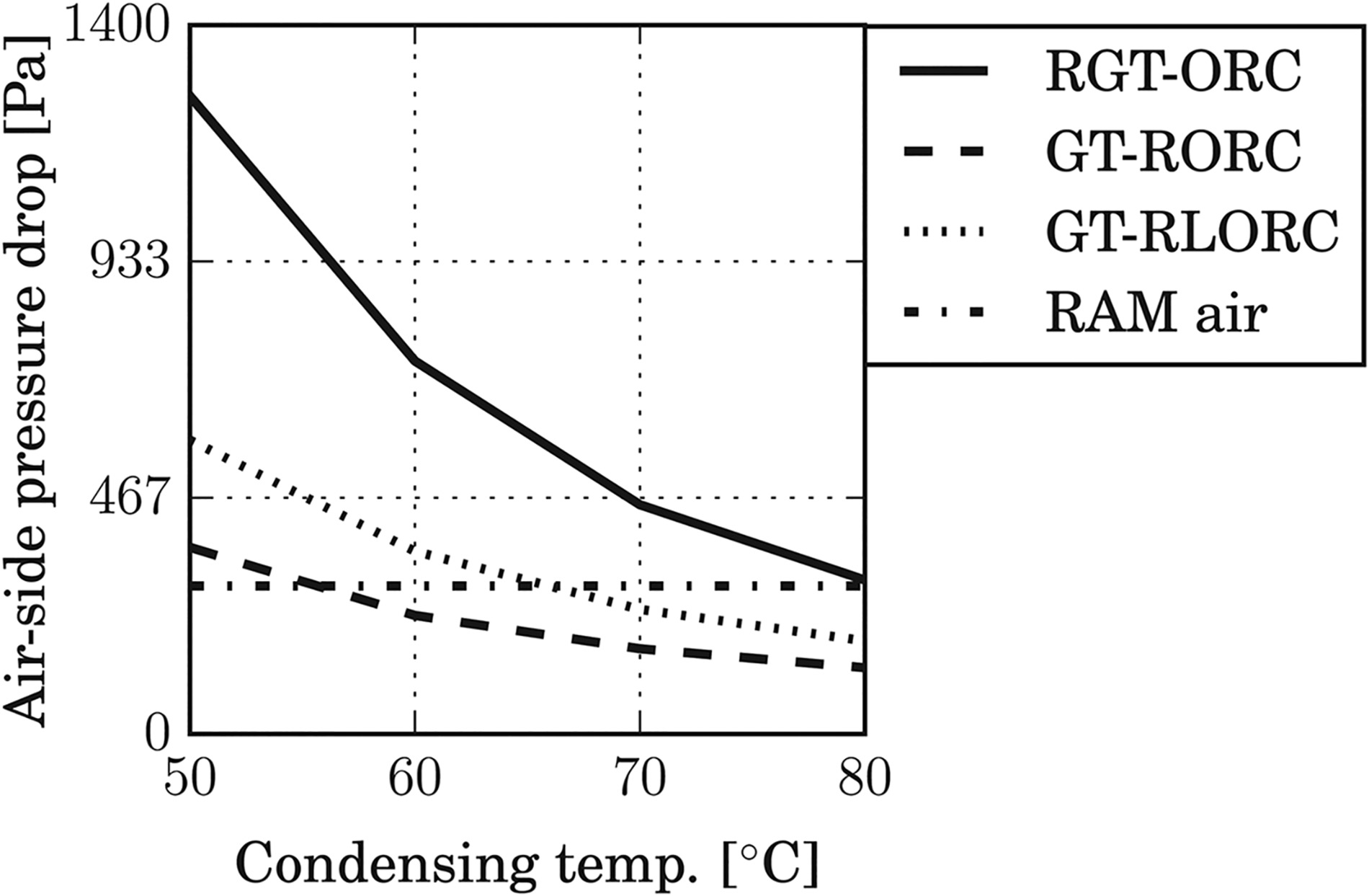
The condenser is installed on the front of the vehicle and its size is taken equal to that of a typical radiator on board of long-haul trucks. The aerodynamic performance of the truck configurations is considered the same. In order to obtain the condensing temperature, the thermodynamic cycle analysis of the candidate CC configurations is simulated with condensing temperatures varying between 50°C and 80°C. This allows to estimate the condenser operating conditions (working fluid mass flow rate, and inlet/outlet thermodynamic states) which are required as inputs to a rating model of the heat exchanger. The model outputs are the required air mass flow rate and the corresponding pressure drop. The condensing temperature is then the minimum value whereby the calculated pressure loss is equal to the dynamic pressure of the air stream entering the radiator at cruise speed, thus guaranteeing that the radiator can operate solely with RAM air.
The rating model of the condenser is based on a one-dimensional discretization of the geometry, as illustrated in Figure 2b.
Mass, energy and momentum balances are evaluated for each cell. Details of the solution strategy can be consulted in the book of Shah and Sekulić (2003). The overall heat transfer coefficient, assuming negligible fouling, reads
where
Following the various assumptions listed by Shah and Sekulić (ibid.), and neglecting the momentum effect, the hot and cold side single-phase pressure drop are computed as
where G is the mass flux,
The correlations for the Colburn and Fanning friction factor of the air side are those for a louvered fin geometry developed by Chang and Wang (1997) and Chang et al. (2000). For the hot side, the Nusselt number and Fanning friction factor are computed with the correlations for flat tubes developed by Spiga and Dall’Olio (1995) under laminar flow conditions, while the correlations of Gnielinski (1976) are used in case of turbulent regime. According to the recommendation of Hesselgreaves (2001), the heat transfer coefficient for a condensing flow is computed with the multiplication factor introduced by Taylor (1990). The two-phase friction factor coefficient is obtained with the method of Lockart and Martinelli (1949). The fin efficiency for the air side is that of a louver fin (Shah and Sekulić, 2003). Finally, the wall resistance (flat tube wall) is computed assuming a flat plate geometry.
The implementation of the condenser design method has been successfully validated by comparison with cases documented in the article of Yadav et al. (2017).
Turbomachinery meanline design
The thermodynamic cycle analysis provides the inputs for the design of the turbines. This task is performed with an in-house meanline code (Pini et al., 2013; Asimptote, 2017). The loss models implemented in this software are listed in the work of Bahamonde et al. (2017). The program has been validated with conventional test cases, i.e., turbines operating with ideal-gas fluids, large Reynolds numbers, and subsonic flows. Efforts are currently underway to perform the validation of the code using mORC machine cases (Head et al., 2016; Pini et al., 2017). Being this work a first exploratory investigation, the design of compressors and pumps, and the effect of blade film cooling on the turbine efficiency is left for future studies.
Preliminary design of the heat exchangers
Plate-fin exchangers are selected, because they are a mature technology that has been widely used in industry for decades, including the automotive and aerospace sectors. Their manufacturing process allows for the use of different metals that can operate with temperatures of up to 840°C, which can be increased to 1150°C by employing ceramic materials (Shah and Sekulić, 2003). Besides, plate-fin heat exchangers were selected for several prototypes of high temperature ceramic µGT power plants (McDonald and Rodgers, 2008). A commercial software is employed for their design (Aspen Technology, Inc., 2015).
The weight of the CC system is an input for the analysis of the fuel economy. As a first approximation, this is taken equal to the weight of the heat exchangers.
Analysis of the fuel economy for a heavy-duty truck
Figure 3 presents a flowchart of the quasi-steady-state models developed for the study of the two long-haul truck configurations considered here: 3a) a conventional vehicle (CV) powered by a Diesel reciprocating engine, and 3b) a hybrid-electric vehicle (HEV). For a detailed explanation on how to model and simulate hybrid and non-hybrid vehicles the reader is referred to the work of Guzzella and Sciarretta (2013).
Figure 3.
(a) Flowchart of the quasi-steady-state model of (a) a vehicle propelled by a conventional Diesel reciprocating engine, and (b) a series hybrid electric vehicle propelled by the proposed combined cycle system.
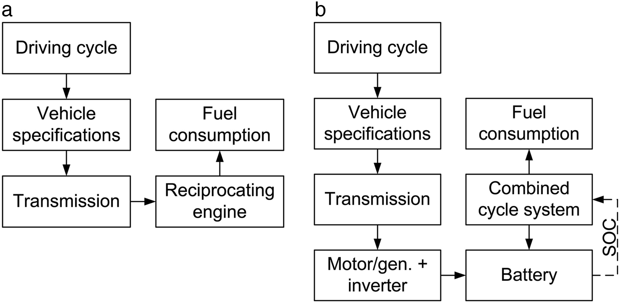
In order to analyze the CV, components from the library have been modified to obtain two new models: a heavy-duty gearbox for the transmission, and a 320 kW reciprocating engine with its corresponding performance map. The required information has been obtained from an open-source database (Alliance for Sustainable Energy LLC, 2016), and it corresponds to a Kenworth T800 truck powered by a Caterpillar C15 engine.
The powertrain configuration selected for the HEV is of the series type, because this configuration allows to operate the gas turbine and the ORC system always under optimal conditions independently from the power demand. For this simulation, several model modules have been modified to include the following components:
a lithium-ion battery, whose charge/discharge curves are obtained from a commercial manufacturer (Saft Batteries, 2005). The specific weight and power have been adjusted, to reflect recent estimations on the characteristics of state-of-art batteries for automotive applications (Bower, 2017).
A 320 kW electric motor/inverter, whose performance maps have been obtained by linearly scaling those from a 220 kW machine (UQM Technologies, Inc., 2017). The regenerative braking power is computed by mirroring the torque-rotational speed efficiency map.
The CC power plant. The start-up and the shut-down of the CC unit is controlled based on the state-of-charge of the batteries. For simplicity, the start-up time and the corresponding energy consumption are not considered in the calculation of the HEV fuel economy.
The fuel economy or trucking efficiency is measured in ton-cargo.km/kg-fuel. This unit takes into account the payload, thus it is a more appropriate figure of merit for comparing the performance of different truck configurations than the specific fuel consumption per km driven (Sharpe and Muncrief, 2015). Moreover, as a first approximation, it is assumed that the energy required to charge the batteries comes from power plants converting renewable energy sources, with negligible emissions and zero fossil-fuel consumption.
HEV control strategy
For missions characterized by long periods at constant speed, a on/off control strategy of the generator is appropriate (Ehsani et al., 2004). The CC system is thus started or stopped if the battery state-of-charge exceeds predefined limits: 90% for the shut-down and 10% for the start-up. To calculate the fuel consumption of the HEV, it is assumed that the battery is discharged in a single cycle and the state-of-charge reaches 10% when the driving mission ends. Furthermore, the combined cycle power plant operates only when the truck is cruising. It follows that the ram air is always sufficient for the condensation of the working fluid of the ORC system, thus no fan is required.
As a first approximation, the energy consumption related to power plant start-up and shut-down is neglected. Such approximation has arguably no effect on the results of this work, because the driving cycle lasts hours, while the start-up/shut-down operations last minutes (De Paepe et al., 2014).
Estimation of the emissions
The HEV emissions are approximated assuming that the turbine operates with natural gas. However, gas turbines running on diesel and achieving very low emission levels are also available (Capstone Turbine Corp., 2010b). As far as CO, HC, NOx, and PM (particular matter) emissions are concerned, estimations are based on tests made by a commercial manufacturer on a 30 kW machine (Capstone Turbine Corp., 2010a). Coefficients are kept constant for the simulation of the entire driving cycle, because the gas turbine is assumed to operate always at design conditions, thus neglecting the start-up and shut-down phases. The emissions per unit energy are then compared against the current limits for heavy-duty vehicles prescribed by the United States Environmental Protection Agency (EPA) (Hoekman and Robbins, 2012), and by the European Union standards (EUROVI) (Reşitoğlu et al., 2015).
The CO2 emissions from the HEV can be computed by using the flue gas composition listed in Table 1. The CO2 discharge from the conventional vehicle is computed assuming an average chemical formula for diesel, namely C12H24 (Date, 2011).
Table 1.
Parameters for the thermodynamic cycle analysis.
Application and results
Preliminary design of the combined cycle
Table 1 enumerates the model parameters considered for the thermodynamic cycle analysis. The CC nominal power output is taken equal to the mechanical power required at cruise conditions, as suggested by Ehsani et al. (2004). For a fully loaded long-haul truck (weight circa 36 tones, according to the limits in the U.S. roadways), trial computations showed that this power is approximately 150 kW.
As far as the µGT model is concerned, the mechanical and combustor efficiency, the Brayton cycle pressure loss, and the recuperator effectiveness are taken from the work of Visser et al. (2011). The total Brayton cycle pressure loss is taken as a fraction of the maximum cycle pressure. The pressure losses are attributed to the various components according to Ref. (ibid.).
The Brayton cycle maximum temperature varies according to the CC-genset configuration under study: (a) the TIT of the gas turbine of the RGT-ORC configuration is set to 925°C. Higher values would result in temperatures of the hot side inlet of the gas turbine recuperator exceeding the limit of 650°C; (b) The TIT of the gas turbine of the GT-RORC configuration is set to 1350°C, which corresponds to the maximum temperature arguably achievable in ceramic turbines; (c) The TIT of the gas turbine of the GT-RLORC configuration is set to 1500°C, which is a feasible value for modern gas turbines with blade cooling. The turbine and compressor polytropic efficiencies are taken from the work of Massardo et al. (2002).
The selection of the ORC working fluid for the GT-RORC and GT-RLORC configurations was performed according to the considerations described in the following. As shown in the Application and Results Section (Figure 5), these power plants feature a gas turbine outlet temperature higher than 600°C. It is thus desirable to select an organic fluid with high thermal stability, in order to minimize the thermodynamic losses associated with heat transfer in the HTHRE. Toluene arguably provides the best performance: it can operate at temperatures as high as 400°C (Invernizzi et al., 2017), and it leads to a comparatively high thermodynamic cycle efficiency, for it features a low molecular complexity (Invernizzi et al., 2007). As far as the RGT-ORC configuration is concerned, systems employing various working fluids were simulated. Ultimately, cyclopentane allowed to achieve the best simulated system performance, likewise due to its low molecular complexity. In case of cyclopentane, a maximum fluid operating temperature of 255°C has been prescribed. This value is lower than the thermal stability limit in contact with stainless steel that is mentioned in the literature (Invernizzi et al., 2017), because a safety margin should be considered given the level of uncertainty.
Figure 5.
Thermodynamic cycle analysis: (a) net efficiency, (b) gas turbine outlet temperature, (c) exchangers heat transfer coefficient.

The values of the ORC model parameters follows common practice for such systems, see, e.g., Bahamonde et al. (2017) and Head et al. (2016). In particular, note that the maximum reduced evaporating pressure is set to 1.1, because larger values have little effect on the cycle thermodynamic efficiency. Moreover, the maximum turbine volumetric expansion ratio is 60. Although such a value my seem too large for a single-stage RIT, the operation of commercial high-temperature 150 kW ORC turbines (Harinck et al., 2013), and a detailed recent numerical study, describing the design of a 10 kW ORC radial inflow expander, supports this assumption (Pini et al., 2017).
ORC condensing temperature
The length, width, and depth of the plate-fin condenser correspond to those of the radiator installed on a KentWorth T800 heavy-duty truck (Autozone, Inc., 2017). The louvered fin and plate geometric patterns are obtained from the work of Yadav et al. (2017).
Figure 4 presents the results of the condenser rating model for several condensing temperatures between 50°C and 80°C, and using the parameters introduced in Table 1. The combined cycle performance has been optimized by tuning the maximum cycle pressure of both the µGT and mORC unit. The condensing temperature is that whereby the air side pressure drop is lower than the air dynamic pressure for a cruising speed of 85 km/h. Thus, see Figure 4, the condensing temperature values for each cycle configuration are: 80°C for RGT-ORC, 60°C for GT-RORC, and 70°C for GT-RLORC. These values may seem high. However, truck radiators operate with water at approximately 85°C. This analysis has been done assuming an environmental temperature of 15°C. Future work should consider the effects of ambient conditions (e.g., higher temperature values) and possibly other solutions and further optimization, as a lower condensing temperature considerably increases the efficiency of the power plant.
Thermodynamic cycle analysis
Figure 5a shows the efficiency of three CC configurations under scrutiny as a function of the Brayton cycle maximum pressure, assuming the condensing temperatures indicated in the previous paragraph; Table 2 lists cycle specifications for the thermodynamic cycles providing the highest performance, while Figure 6 shows the corresponding temperature-entropy diagrams.
Table 2.
Optimal cycle specifications.
Figure 6.
Temperature entropy diagrams of the optimal specifications: (a) RGT-ORC, (b) GT-RORC, (c) GT-RLORC.
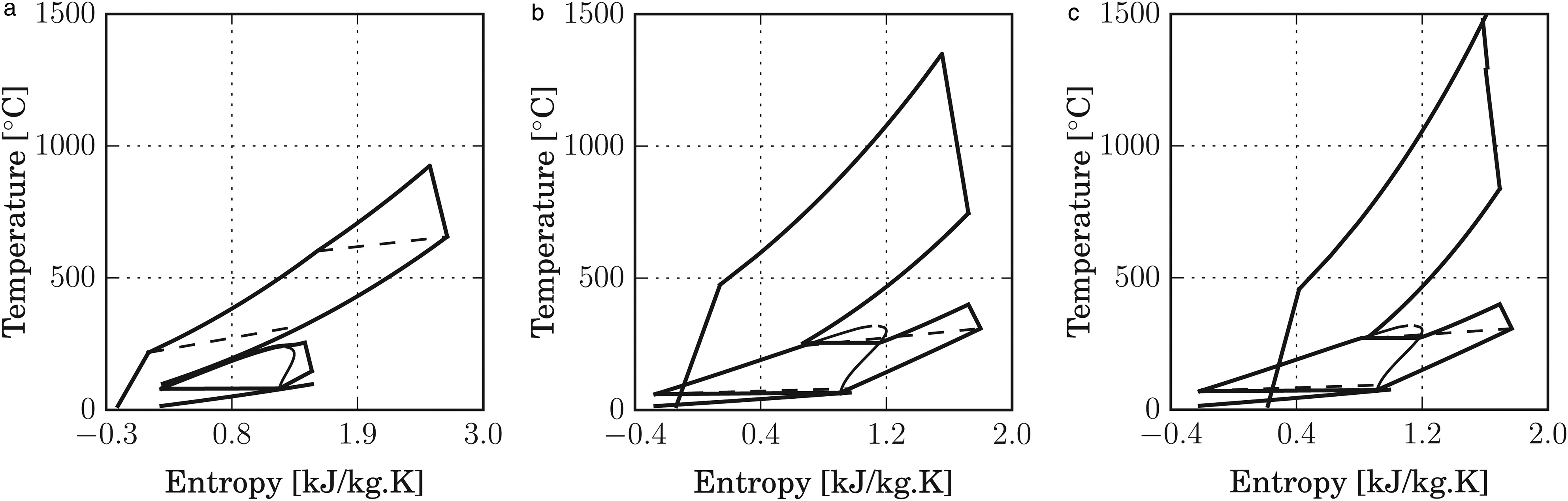
Figure 5 shows that the GT-RLORC system allows to obtain the highest estimated conversion efficiency. This is due to a combination of two factors: the large difference between maximum and minimum temperature of the thermodynamic cycle (1500°C and 70°C); and the higher efficiency of the bottoming cycle, due to the larger amount of thermal energy harvested from the GT exhaust gases. The mORC units of the GT-RORC and GT-RLORC systems feature considerably higher thermal efficiency if compared to those from other ORC units designed for automotive waste heat recovery, see e.g., (Shi et al., 2018). This is a result of the high gas turbine exhaust temperature (approx. 800°C), which allows raising the ORC turbine inlet temperature to a very high value, namely 400°C.
Despite the fact that the GT-RORC and GT-RLORC systems feature the best predicted thermal efficiencies, these configurations are suboptimal, because of the considerable exergy destruction affecting the heat recovery exchanger, see Figure 6b and c. An optimal system configuration which mitigates this drawback would include partial recuperation in the gas turbine. In this case, it would also be possible to reduce the TIT of the gas turbine, which could also be beneficial. Other cycle configurations will be studied in future stages of this research.
The thermal efficiency of the gas turbine has the largest impact on the overall thermodynamic efficiency of the system. It follows that the optimal Brayton cycle pressure is close to that of the stand-alone µGT. Thus, for the CC system featuring a gas-to-gas recuperator, the optimal pressure is 4.4 bar. The CC systems with no recuperation require a higher maximum pressure: 15.3 bar for the GT-RORC system, and 14.2 bar for the GT-RLORC system.
Due to the large gas turbine inlet temperature in the GT-RORC and GT-RLORC systems, the corresponding outlet temperature largely exceeds 650°C for the optimal operating conditions: 746°C and 838°C, for the GT-RORC and GT-RLORC configurations, respectively. Hence, these power plants require a HTHRE manufactured with special alloys or ceramic materials. On the other hand, the RGT-ORC system was designed following specifications which are representative of the state-of-art for µGT and mORC turbo- generators. It can operate with a heat exchanger manufactured with conventional materials, because the turbine outlet temperature is approximately 650°C. The RGT-ORC configuration is, from a technological point of view, the most feasible solution among those investigated.
Figure 5c presents the total heat transfer coefficient UA as a function of the maximum pressure in the Brayton cycle. Those values, to a first approximation, are proportional to the size of the heat exchangers. The RGT-ORC System features a small µGT pressure ratio and a small specific work, hence it requires large mass flow to achieve the targeted power output. Its recuperator is characterized by large effectiveness (0.87), hence it features a large UA value. Moreover, note in Figure 6a that the temperature difference between the hot and cold streams in the HRVG is small when compared against the other cases (see Figure 6b and c for GT-RORC and GT-RLORC systems, respectively); the required heat transfer area is hence larger. It follows that the RGT-ORC system features the largest heat exchangers.
The energy carried by the gas turbine exhaust gases is larger in cycles without recuperation. As a result, the GT-RORC and GT-RLORC systems feature a bottoming cycle with larger power output. This is beneficial for the ORC turbomachinery, because it leads to larger flow passages, thus reducing scaling effects (e.g., tip clearance losses). However, the blade height of the gas turbine might be rather small, which in turn negatively affects its performance.
Two cycle configurations were selected for the design of the turbines and the heat exchangers: the RGT-ORC system, as it is the CC-configuration with the highest technological readiness; and the GT-RLORC system, because it features the best predicted efficiency.
Preliminary design of gas and ORC turbines
The combination of the low enthalpy drop in an ORC expansion, and the constraint on the volumetric flow ratio, allow to realize a single-stage radial inflow turbine for all the bottoming cycles. The same type of expander is used in the µGT of the RGT-ORC system, due to its small pressure ratio (4.4). The other µGT systems feature a four-stage axial machine, in order to limit the rotational speed to values not exceeding 150 krpm, thus easing the design of the bearing system. The selection/design of an electric generator coupled to all these turbomachines should not present a major challenge, given the current level of technology: µGT operating with rotational speeds as high as 300 krpm have been already successfully coupled with high-speed electrical generators (Visser et al., 2011). Table 3 itemizes the most important constraints utilized in the optimization. The work of Bahamonde et al. (2017) presents a detailed explanation of the turbine preliminary design method.
Table 3.
Main constraints for the turbine optimization.
Table 4 lists the main results of the meanline design for the µGT and mORC turbines of the RGT-ORC and GT-RLORC configurations. The difference in the total-to-static efficiency can be explained by means of the size parameter and the volumetric expansion ratio (Perdichizzi and Lozza, 1987; Angelino et al., 1991). The size parameter is a dimensional quantity that is proportional, for an optimized specific diameter, to the actual turbine dimensions (Angelino et al., 1991). It follows that machines with a small size parameter are generally affected by considerable tip clearance losses and Reynolds effects. Likewise, efficiency penalties from compressibility effects and large flow area variations are related to a large volumetric expansion ratio. The size parameter of the radial inflow gas turbine of the RGT-ORC is the largest, while the volumetric expansion ratio is the smallest, resulting in the best total-to-static efficiency. Conversely, the lower efficiency of the other turbines is a result of the combination between the large volumetric expansion ratio and the small size parameter. In particular, note that the cyclopentane machine seems to be strongly affected by the low size parameter, which is mostly caused by the comparatively lower power output (half the one of the toluene turbine). Finally, for the axial turbine, note that the constraints on the blade height and rotational speed prevent the stages from achieving optimal specific speed.
Table 4.
Turbine specifications.
Preliminary design of the heat exchangers
Figure 7 shows the weight of the heat exchangers for the RGT-ORC and GT-RLORC systems. The contribution of the different HEX's to the overall weight of the CC unit reflects the UA values corresponding to the thermodynamic cycle calculation.
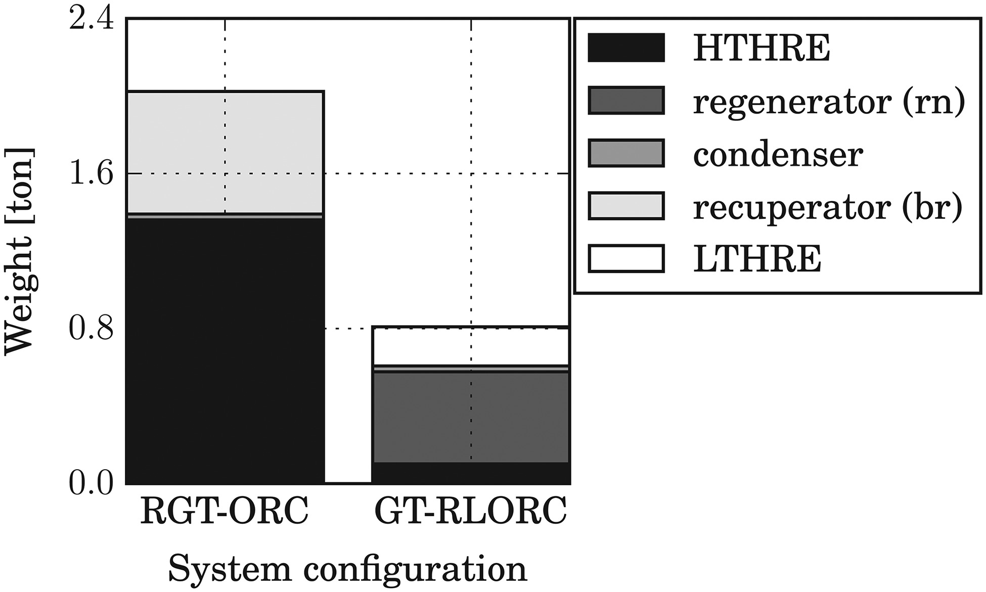
The weight of the CC system is critical, for it must be added to the weight of the batteries, potentially reducing the truck payload. Due to this reason, only the lightest system, the GT-RLORC, is considered for the fuel economy analysis. The total volume of the of the heat exchanger cores of system GT-RLORC is lower than 0.5 m3. Thus, arguably, assembling the combined cycle system within the vehicle structure would not be a major challenge.
Analysis of the fuel economy and estimation of the emissions
Table 5 summarizes the parameters of the quasi-steady-state simulation with the corresponding information sources. Two types of systems were analyzed: a heavy-duty vehicle powered by a diesel reciprocating engine (CV), and a heavy-duty vehicle with a series hybrid powertrain (HEV). The total weight of both configurations is equal to the legal limit of 80000 pounds in the United States roadways. Consequently, as shown in Figure 8b, the cargo weight varies as function of the vehicle type and battery capacity. The efficiency map of the reciprocating engine has been scaled to match expected performance improvements in the upcoming years; its peak value is 0.50. Additionally, and as a first approximation, the battery energy efficiency is kept fixed at 0.95 (Ehsani et al., 2004). The CC system efficiency is slightly lower than that of the GT-RLORC prime mover, to take into account generator and transmission losses. Finally, thanks to the multi-fuel capability of gas turbines, two types of fuel have been considered for the HEV: diesel and compressed natural gas (CNG).
Table 5.
Key parameters of the quasi-steady-state simulation.
[iv] cGibble and Amar (2016).
[v] dRahman et al. (2013).
[vi] eEhsani et al. (2004).
[vii] fBower (2017).
[viii] gStodolsky et al. (2000).
Figure 8.
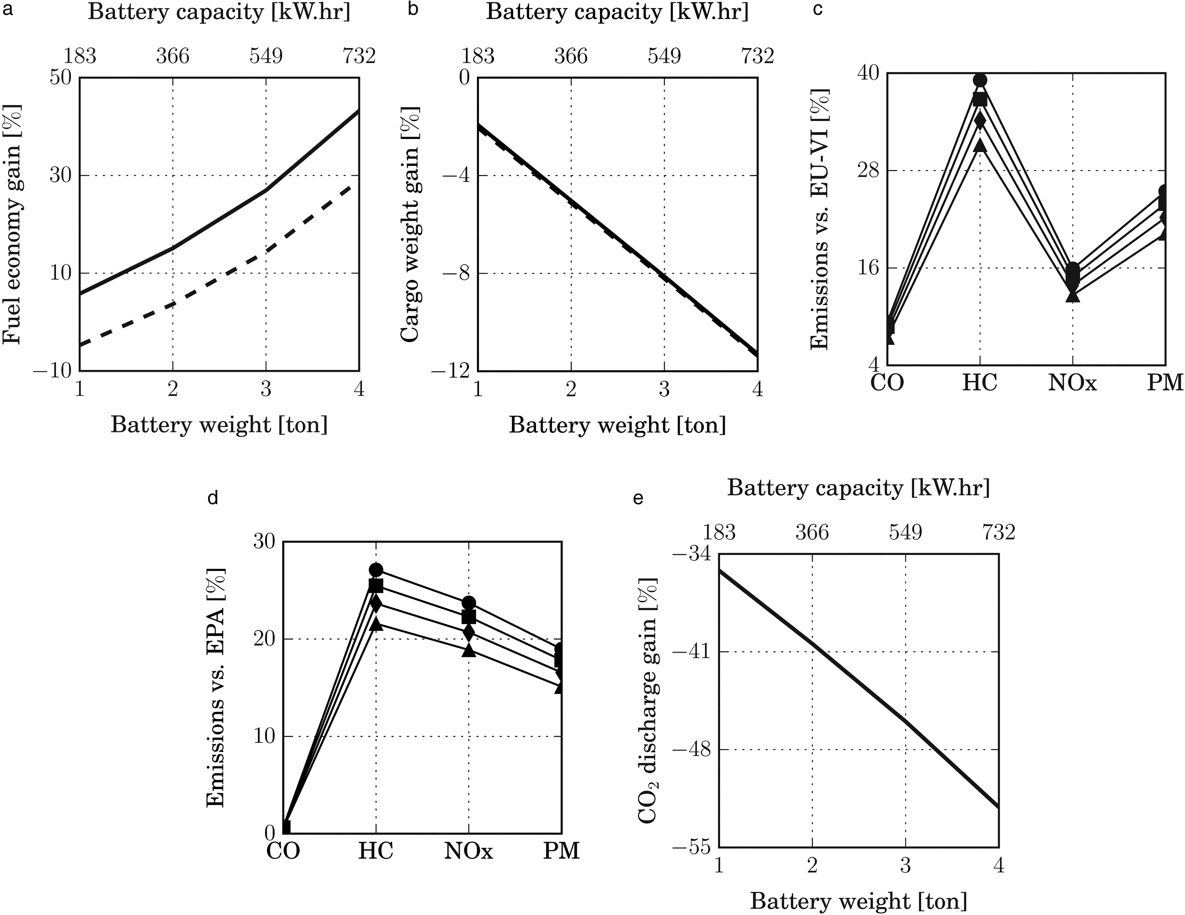
(a) HEV fuel economy gain and (b) cargo weight gain as a function of the battery capacity and with the CC system operating with (−) natural gas, and (- -) diesel. (c and d) Emissions compared against the Euro VI, and EPA standards; they are computed for a battery weight of (●) 1 ton, (▪) 2 ton, (♦) 3 ton, and (▴) 4 ton. (e) CO2 emissions of the HEV compared against the ones from the CV.
Driving cycle
Long-haul trucks spend 85% of their mission in cruise conditions (at 85 km/h), and might have an idling time between 6 and 16 h (Stodolsky et al., 2000; Rahman et al., 2013). A realistic mission profile has been constructed with this information, because standard driving cycles do not represent actual patterns (Zhao et al., 2013). The velocity-time profile is formed by two standard driving cycles and idling time: Urban Dynamometer Driving Schedule for Heavy-Duty Vehicles (UDDSHDV): 0–0.4 h; Heavy Heavy-Duty Diesel Truck Schedule (HHDDT): 0.4–11 h; idling: 11–17 h.
Fuel economy and emissions
Table 6 presents the results for the CV. The miles-per-gallon (mpg) are close to those obtained in a similar study (ibid.). Figure 8 shows the results of the HEV analysis for different battery capacity values. These results are expressed as percentage gain with respect to the CV benchmark.
Table 6.
Results of the simulation performed on a vehicle employing a diesel reciprocating engine.
| Miles per gal mpg | Fuel economy ton-cargo.km/kg-fuel | Payload ton | CO2 emissions kg-CO2/ton-cargo.km |
|---|---|---|---|
| 5.4 | 79.63 | 30.41 | 6.2 × 10⁻³ |
The fuel economy has units that feature the kilograms of fuel in the denominator; it is thus affected by the corresponding LHV. For instance, in an analysis where the payload and the required mechanical energy remain constant, the vehicle employing a fuel with higher LHV will require a lower mass of fuel, thus featuring a higher fuel economy parameter.
The fuel economy gain is shown in Figure 8a. Since the results are affected by the LHV, the solution using diesel allows to provide a clear comparison between the CV and the HEV powertrains. The prime mover of the HEV powertrain is less efficient than the reciprocating engine: it has additional transmission losses, and the efficiency of the CC system is lower than that of the reciprocating engine (0.44 and 0.50 (peak), respectively). As a result, a HEV with a small battery will necessarily feature a negative fuel economy gain, as shown in Figure 8a. Since it is assumed that the battery is fully charged with renewable energy, it is necessary to increase the battery size to obtain a positive gain: at least 300 kW.hr, see to Figure 8a.
However, if the fuel is CNG, the fuel economy of the HEV powertrain is better than that of the CV for all considered battery capacity values, and it also features a higher fuel economy than the system operating with diesel. This is due to the higher CNG LHV, which leads to a lower amount of consumed kg-fuel.
Observe in Figure 8a that the fuel economy can be largely improved by increasing the battery capacity. However, since the total weight cannot exceed 36.29 ton, increasing the fuel economy requires reducing the cargo weight, as shown in Figure 8b. The analysis of the corresponding economic trade-off is left for future developments. The prospect of natural gas as a fuel for long-haul trucks is positive, because its price is forecasted to be lower compared to oil in the United States (Brown, 2017). Moreover, even if the constraint on the weight is released and the payload remains constant, the fuel economy increases proportionally to the battery capacity, as it can be inferred from the trend in Figure 8a.
The analysis of the emissions was performed only for the HEV CC system operating with CNG. However, the gas turbine can also operate with diesel, and it has been proven that the corresponding emissions are dramatically lower than those from a reciprocating engine (Capstone Turbine Corp., 2010b). Figure 8c and d present the estimated HEV powertrain emissions compared to the EPA and EURO VI standards. The HEV powertrain produces emissions that are well below the regulated limits, without the need of an exhaust after-treatment unit.
Finally, Figure 8e illustrates the comparison of the computed CO2 emission from the HEV vs that of the CV. A reduction of 30% with respect to the CV propelled by a next-generation diesel engine seems achievable.
Concluding remarks
This paper documents a preliminary assessment of a hybrid electric powertrain for heavy-duty vehicles employing a combined cycle power plant composed by a micro gas turbine and a mini organic Rankine cycle system. As test case, the performance of the proposed powertrain concept is evaluated for a long-haul truck (weight approx. 36 ton) performing a representative mission. For the μGT, two fuel options were explored: diesel and compressed natural gas. As benchmark for the HEV, a conventional truck powered by a diesel reciprocating engine was considered. The relevant conclusions stemming from this work are:
The best combined cycle system features an estimated efficiency of 0.44. It is constituted by a non-recuperative gas turbine and a regenerative organic Rankine cycle system with an additional low temperature heat recovery exchanger. This system requires forefront technology: a μGT with film blade cooling for a maximum operating temperature of 1500°C, and a high- temperature heat recovery exchanger manufactured with special alloys or ceramics that can operate at 840°C.
For a diesel-fueled hybrid powertrain, the fuel economy (ton-cargo.km/kg-fuel) can be improved by employing a battery with a capacity of at least 300 kW.hr. The hybrid vehicle powered by natural gas showcases even more potential, as it features a higher fuel economy with ultra-low emissions.
If compared with EPA and EURO VI standards, the hybrid powertrain fueled by natural gas produces emissions which are much lower than those prescribed, without the need of an exhaust after-treatment unit. Likewise, the CO2 discharge produced by the HEV CC powertrain fueled by natural gas is lower than one fifth that of the next-generation diesel reciprocating engine, which served as a benchmark.
In summary, this work demonstrates that the adoption of a combined cycle system in a hybrid powertrain has a considerable merit potential in terms of fuel economy and exhaust emissions. Future planned investigations will expand the analysis to cover these aspects: