
Introduction
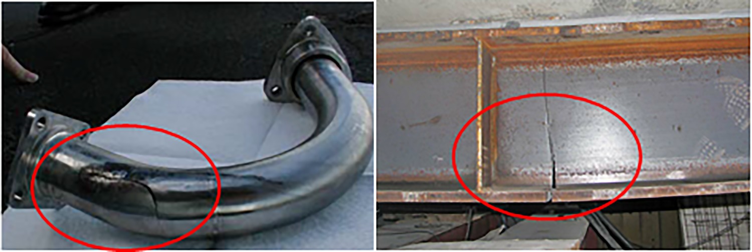
Structures such as external pipeline, fuselage and blade in aeronautical and astronautical engineering play an important role in transfering fuel oil, protecting passengers and providing power and so forth (Barry, 1998). The single type consists of only one component or several components in series, while multiple type include two or more elements connected by clamps or connections. Due to the dynamic load excitations of rotor vibration, fluid pulsation and oscillating combustion during their working process, these engineering structures are prone to have breathing cracks which would seriously affect the integrity and reliability of structures (Timashev and Bushinskaya, 2016). For example, the hydraulic pipe of one aircraft engine resulted in an aircraft fuel tank fire due to resonance fracture and oil leakage, one accident was caused by the crack and leakage of a turbojet engine oil pipe due to impact oscillation. Therefore, in order to ensure the sustainable and stable operation of aeronautical and astronautical engineering structures, and to avoid major safety accidents, it is necessary to identify the structural breathing cracks as early as possible.
For the detection and localization of breathing cracks in engineering structures, numerous methods monitoring changes in static or dynamic structural features caused by cracks have been proposed and applied (Balageas et al., 2010; Kourehli, 2015). To detect and measure cracks, an auto inspection system extracting crack information using Charged Couple Device (CCD) camera and image processing technique has been developed (Yu et al., 2007). Using photographic measurements and wavelet transform algorithm, the slope discontinuity of a beam was identified to indicate the existence and position of cracks (Nigam and Singh, 2020). Based on the wave propagation theory, data of cracked pipeline were collected by piezoceramic transducer and processed by applying wavelet packet decomposition. And then, the root-mean-square deviation (RMSD) was defined as an index for cracked pipeline (Du et al., 2017). Similar to this, researchers (Bhalla and Kiong Soh, 2003) utilized the piezoceramic transducer to measure electro-mechanical impedance (EMI) of cracked structures, and applied its real and imaginary parts respectively as crack indicator. Apart from EMI, magneto-mechanical impedance (MMI) was also used for crack identification. Researchers (Zagrai and Çakan, 2008, 2010) utilized the Magneto-Elastic Active Sensor (MEAS) and impedance analyser to measure MMI and observe its changes for damage detection. The fundamental principle of above methods is simple and testing results on laboratory specimens have verified their reliability and effectiveness. However, these methods would be more suitable for simple structure with single crack fault because that the crack position should be known in prior for the installation of measurement instruments. This drawback would limit their further application to other complex engineering structures that may have multiple cracks.
According to previous studies and results, vibration-based features including modal properties (MP), frequency response function (FRF), output spectrum (OS) and transmissibility function (TF) could be used as effective damage indicators for diagnosing engineering structures with multiple breathing cracks (Prime and Shevitz, 1995; Krawczuk and Ostachowicz, 1996). Compared with others, TF would be more sensitive and useful. For example, it is defined as the ratio of outputs between two different structural points and can be computed utilizing outputs directly. It is a function of structural properties such that it fully reflects intrinsic characteristics of structures with a wide range of frequency and it would be more sensitive to changes in sub-structural parameters due to cracks. Treating breathing cracks as internal force applied to the multi-degree-of-freedom (MDOF) structure, properties of TF were summarized to detect faults in a metal panel (Johnson and Adams, 2002). Later, improved damage indexes were defined to investigate conditions of breathing cracks in a rotorcraft woven composite plate (Kess and Adams, 2007) and a rolling tire (Johnson and Adams, 2006) respectively. To improve the sensitivity of damage indicators and eliminate the effects of inputs, output-based weighting factor was added to increase the difference of TFs between intact and damaged structures (Li et al., 2015a,b). Using operational deflection shape (ODS) at excitation and higher harmonic frequencies, transmissibility of operational deflection shape (TODS) was defined and an outlier detector named teager energy operator (TEO) was used for cracks in a cantilever beam (Li, 2018). To reduce the effects of frequency bands on indicators, output data were processed by wavelet transform (WT) and wavelet spectrum-based TF was used for crack identification (Li et al., 2017).
Since structures with breathing cracks behaviour in a nonlinear way, their nonlinear dynamic models could also be descried by the Volterra series. According to this, nonlinear output frequency response function (NOFRF) was used to compute TF and be employed for localizing multiple cracked elements in a MDOF system (Peng et al., 2007). For the cracks in a reactor coolant pump, one NOFRF TF-based methods applying dual harmonic excitations was proposed (Wang and Ma, 2012). Later, similar TF and indicator were applied for crack faults in a hydraulic pipeline (Li et al., 2015a,b). In order to avoid the estimation of each order NOFRF with complex algorithms, method using nonlinear outputs directly was developed (Zhao et al., 2014). Considering NOFRF and higher harmonic response (HHR) together, a novel crack position index (CPI) was defined for the localization of cracks in a single-span double-disc rotor (Liu et al., 2019). Since the second-order output spectrum (SOOS) is more sensitive to crack-induced nonlinearity, a more sensitive SOOS TF-based damage indicator was proposed for breathing crack faults in a cantilever beam (Jing and Li, 2016).
Above TF-based methods provide information of existence and location of cracks. However, one very important issue of these methods is that features from intact structures are required during the derivation of damage indexes. This requirement could affect these methods’ practicability when the state of benchmark structures cannot be evaluated. To overcome this limitation, a novel vibration-based crack localization method for engineering structures without reference is proposed in this paper. The significant novelties of this paper have, (1) Using outputs of damaged chain-type engineering structures solely, local damage features are derived utilizing additional masses; (2) With the TF-based damage indexes, a novel approach is proposed and its availability is illustrated through simulations on the chain-type MDOF model with multiple breathing cracks.
This paper has five main parts. INTRODUCTION presents the background, some related crack localization methods and the main motivations of this paper. The second part introduces the general chain-type MDOF model of cracked engineering structures and analyses of its dynamic characteristics. The next part derives local damage features and indexes, and summarizes procedures of the novel method. Results of simulation studies are shown in the SIMULATIONS. Finally, conclusions and discussions of this paper are presented in the last part.
Dynamics of engineering structures
Model of engineering structure
In some engineering structures such as external pipelines and beams, there is no connection between the head and end of structures such that they are referred to as open chain type structures (Figure 1). To consider this type of structures, their dynamic model is simplified as a general chain-type MDOF model composed of some mass-damper-spring elements (Ewins, 2009).
As shown in Figure 2, the MDOF model uses coordinate
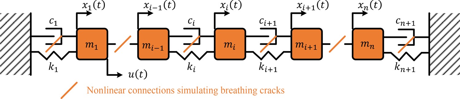
If there are breathing cracks in engineering structures, nonlinearities are introduced into damper-spring connecting elements in the MDOF model. Thus, the nonlinear restoring force caused by cracks between masses
(2)
where
Dynamic response of the MDOF structure
When the excitation in (1) is a cosine function, the output response of mass
where V is the maximum order of harmonics,
Substituting (3) into (1) and (2), and extracting the coefficients of
where
With the matrix
It can be seen that nonlinear output spectra at higher harmonic frequencies (more than two) are just decided by structural physical parameters and nonlinear forces induced by cracks.
Crack localization approach
Damage features and indicators
Considering mass
(6)
Now, if additional mass
(7)
Adding mass
(8)
Observing (6), (7) and (8), it is found that the change of value of mass
Writing (6), (7) and (8) into a matrix form gives
where
It is shown that if there is no fault around mass
To determine the singularity of matrix
According to the analysis above, result
Procedures of Method
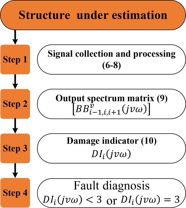
Based on the damage indicator in (10), a novel crack localization approach is developed. Its procedures are outlined and explained as follows.
Developed method includes four main steps. In steps 1 and 2, time domain output data collected from the engineering structure under estimation are processed and transformed into frequency domain to form matrix
Simulations
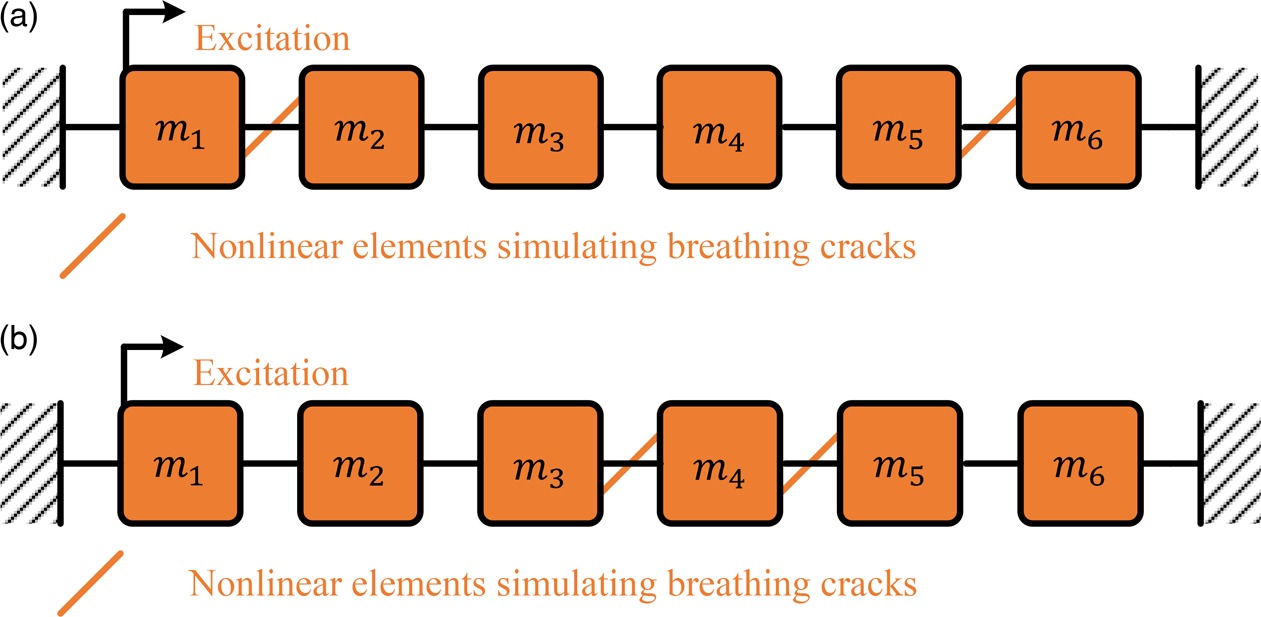
To verify the effectiveness of above damage indicator and localization method, two simulation cases on the chain type structure with six DOFs (Figure 3) are studied respectively. In case one, one fault is between masses
Structural parameters of simulation models are shown in Table 1.
Table 1.
Parameters of simulation.
According to (2), faults are simulated as nonlinear elements with corresponding nonlinear parameters
With the procedures of approach in Figure 4, results of simulation cases are shown in Figure 5.
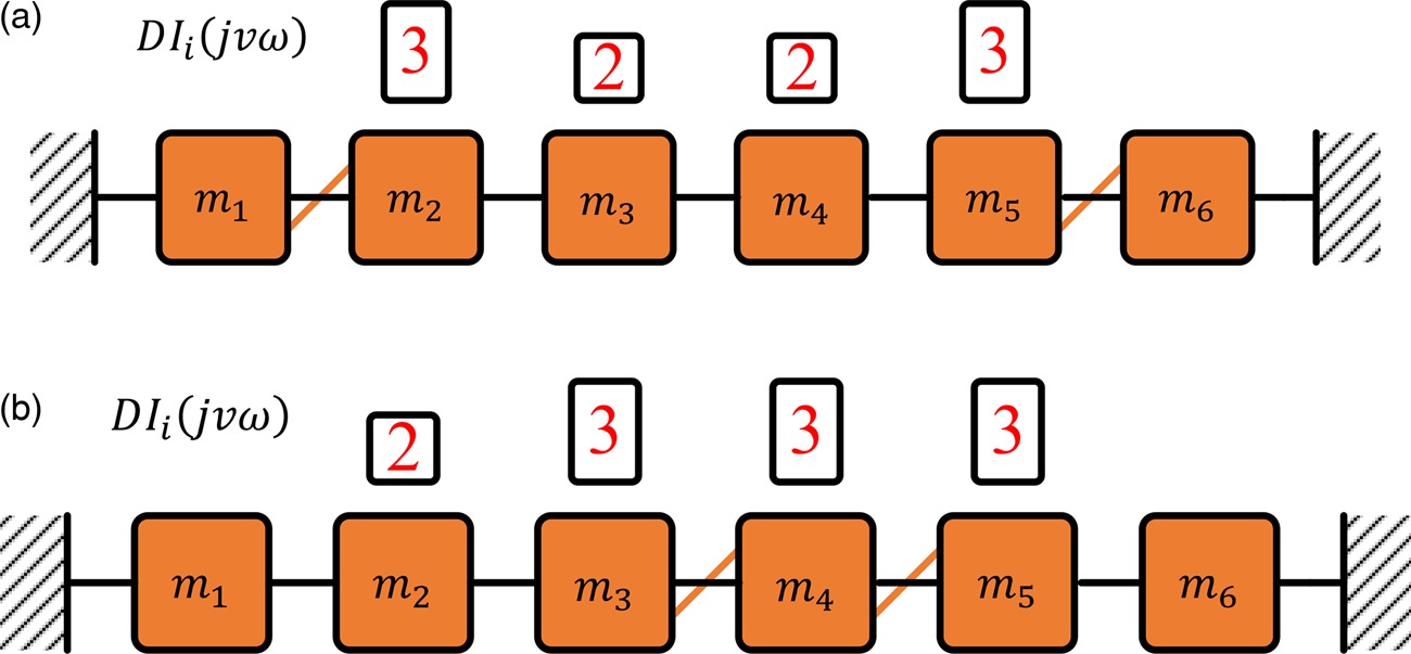
It can be seen that values of
Overall, detected results from chain-type structures are consistent with the crack positions in case setups. Thus, the effectiveness of proposed method is verified by these two simulation cases.
Results and discussions
To avoid benchmark features from intact structures during the derivation of damage indicators in previous methods. A novel vibration-based crack localization method of engineering structures without reference is proposed in this study. The main conclusions are summarized as follows.
By simulating effects of cracks as nonlinear restoring forces, a general MDOF model with nonlinear connecting elements could be used to describe chain-type engineering structures’ dynamic behaviour.
Adding additional mass to the structure, three similar equations from structure under estimation could be used to form one matrix, and its rank could be an effective damage indicator to indicate the existence and position of cracks.
Results from simulations on the chain-type structures with multiple nonlinear elements (cracks) demonstrate that the proposed approach could be an effective tool to estimate the state of cracked engineering structures.
In the future study, experimental verification of this approach and extension of this approach to other kinds of engineering structures should be considered more.
Nomenclature
structural mass matrix
structural damping matrix
structural stiffness matrix
structural acceleration vector
structural velocity vector
structural displacement vector
excitation vector
nonlinear restoring force vector
nonlinear structural damping parameter
nonlinear structural stiffness parameter
maximum order of nonlinear restoring force
maximum order of harmonics
the
the
frequency domain nonlinear force vector
a novel damage indicator.