
Introduction
Cascade test is an important means to obtain compressor profile performance. A large number of cascade tests have been carried out to study the performance of classical two-dimensional profiles . Due to the limited spanwise size of the test cascade, flow separation will occur at the end-wall, resulting in blockage of the end-wall flow and contraction of the main flow path. Axial velocity density ratio (AVDR) will be large, and flow in mid-span will deviate from the two-dimensional flow. To make the test results accurate and reliable, it is necessary to control the end-wall separation to reduce the AVDR.
End-wall suction and blade slotting are the methods that can be used to control separation. End-wall suction is an active control method that reduces separation by directly suck out low-energy fluid near the end-wall. Many studies have adopted end-wall suction in cascade test (Erwin and Emery, 1951; Herrig et al., 1957; Song and Ng, 2004; Starken et al., 1975), and achieved good results. However, end-wall suction requires additional equipment and energy. On the other hand, for different cascades and working conditions, the size and position of the end-wall separation are different, and the required extraction volume and position are also different. The corresponding guidelines are lacking.
Blade slotting is a passive control method. By opening a channel between the pressure surface and the suction surface of the blade, the fluid flows from the pressure surface to the suction surface along the channel driven by the pressure difference, which forms a jet impact on the low-energy fluid and weakens the separation. The concept of blade slotting was first introduced into compressor by Rockenbach (1968), and a series of experimental studies were conducted by NASA (Keenan and Bartok, 1968; Mikolajczak et al., 1970; Rockenbach, 1968). They made slots in different rotors and stators and compared them with datum blades. The results show that blade slotting can control the trailing edge separation and reduce the wake width, but it cannot control the separation near the end-wall. The scholars have carried out slot research on the cascades. Zhou et al. (2008a,b, 2010) conducted full-span slotting and studied the effects of different slot widths, angles and positions on cascade performance through experimental and numerical methods. Ramzi et al. (2011), Ramzi and Abderrahmane (2013) conducted numerical calculations of slot on 2D profile and full-span slot on 3D cascade, and believed that slotting could control the suction surface separation and end-wall separation. Wang et al. (2012) found that when the negative incidence angle is large, the slotted cascade may increase the suction surface separation, which makes the cascade performance worse. Jiaguo et al. (2018) developed a slotted control method for high-load cascade separation, and conducted experimental and numerical studies. It is found that jet inhibits the development of corner separation. Blade slotting greatly improves the aerodynamic performance of the cascade under separation conditions, but causes additional losses without separation conditions. Because the full span of cascade is slotted, the 2D profile is actually changed.
Blade end slotting has also been studied by scholars. Compared with full-span slot, end slot can control the separation of corner regions without changing the two-dimensional profile at mid-span. Tang et al. (2019, 2020) compared the full-span slot and the end slot (20% span) in a cascade, and found that both the full-span slot and the end-slot could change the flow structure near the end-wall and recombine the flow at a large positive incidence angle. The adaptive jet of the channel charges the low momentum fluid downstream, inhibits its migration to mid-span, thus reducing the corner separation and improving the performance. However, the loss of the full-span slotted cascade may be larger than that of the end-slotted cascade due to the mixing of the jet and the main flow at mid-span. Liu et al. (2016) studied the effect of end slot of different solidity and aspect ratio. Sun et al. (2021) optimized the shape of the slot. Ma et al. (2021) studied the influence of blade end slots on corner separation caused by shock wave/boundary layer interaction for a supersonic compressor cascade, and compared four different blade end slots. It was found that the blade end slot improved the corner separation, and the optimal position was slightly downstream of the initial separation point. For the compressor stage, Yoon et al. (2019) conducted end slot for a three-stage compressor and found that the slotting enhanced the axial momentum near hub while weakened the radial migration, thus weakening the corner separation near hub.
The previous research mainly analyses and optimizes cascade slotting for the purpose of weakening separation and improving cascade performance. For the cascade test to obtain performance of two-dimensional profile, the purpose of control separation is to reduce the influence of end-wall separation on the mid-span flow and restore the two-dimensional flow at mid-span. It is not important to reduce the end zone loss and enlarge the diffusion factor of cascade. How to achieve the above purpose through blade slotting still needs to be studied.
This paper proposes a method of blade end slot for cascade test. The slotting controls the end-wall separation and helps the flow at mid-span to become two-dimensional. Firstly, cascade and slot geometry are introduced. Then the numerical method is introduced. Thirdly, the effect of blade end slot on the performance at mid-span is compared, and flow at mid-span is analysed. Next, 3D flow structures are exhibited and the effect of slot jet on corner separation is analysed. Finally, main conclusions are illustrated.
Geometric model
High load compressor cascade
The datum profile investigated in this work is cut-off at the mid-span of a certain axial compressor rotor. Limited by the test facility, chord length was scaled down to 0.5 times for a higher aspect ratio. Table 1 lists the design parameters for the profile after scaling. Cascade tests were performed on a variable density plane cascade wind tunnel at China Aerodynamics Research and Development Center (CARDC). Detailed test introduction, including test facilities parameters, measurement methods, test conditions, etc., and test results have been published by Wang et al. (2024).
Slot design
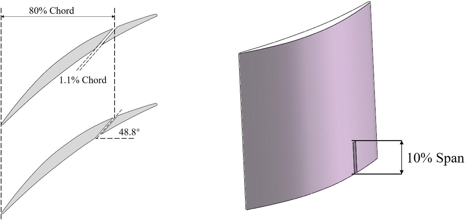
In order to introduce a suitable jet flow near the end-wall to control the corner separation, the slot design was carried out. The design parameters of slot are presented in Figure 1. The aim of slotting is to control the flow in the mid-span of the cascades to be close to two-dimensional flow so as to reflect the real performance of profiles in the test, not to improve the performance of the cascade. Therefore, a complex geometry of slots is not necessary, although it may have a good effect in reducing the loss of cascades. Straight slots were chosen because they have the advantage of simple structure and few parameters while satisfying the aim. A blade end slot (covering 10% of the span from the end-wall) was selected to control the separation near the end-wall without affecting the performance of the mid-span of the cascade. Some literatures (Ma et al., 2021; Ramzi et al., 2011; Rockenbach, 1968) suggested that slot should be near the separation start point. However, it mainly reduces the trailing edge separation of the 2D blade, and the effect on the end-wall separation was not obvious (Ramzi and AbdErrahmane, 2013; Rockenbach, 1968). In order for the slot jet flow to impact the center of separation, the outlet of the slot was set at 80% chordwise position. The width of the slot was set to 1.1% of the chord length, and the angle from the axis was 48.8 deg.
Numerical modeling
CFD modelling
ANSYS CFX was used in this study to solve the Navier-Stokes equation. Quasi-2D profile, 3D datum cascade and 3D slotted cascades were calculated. The single-passage is adopted due to the periodicity of the cascade. Half of blade passage in the spanwise direction was considered because the flow in cascade symmetrically along the plane of 50% span. Extension sections with 1- and 2-times chord length were arranged upstream and downstream of the cascade. The measuring position of the inlet and outlet flow was 50% chord length away from the leading and trailing edge, which is the same as the measurements in test.
The total pressure and static temperature at the inlet boundary and the static pressure at the outlet boundary measured in the test were set in the simulation, which ensured that the inlet Mach number was consistent with the test value. No-slip and adiabatic conditions were imposed on all solid walls, including surface of blade and slot and end-wall. For 3D simulation, 50% span section was set to symmetric plane. For the quasi-2D calculation, the upper and lower end-walls were set as periodic boundaries, and the flow of the two-dimensional profile was simulated by an infinite cascade. The SST turbulence model was used to account for the turbulence flow. The free stream turbulence intensity was set as Tu = 1% at the inlet according to test.
Mesh
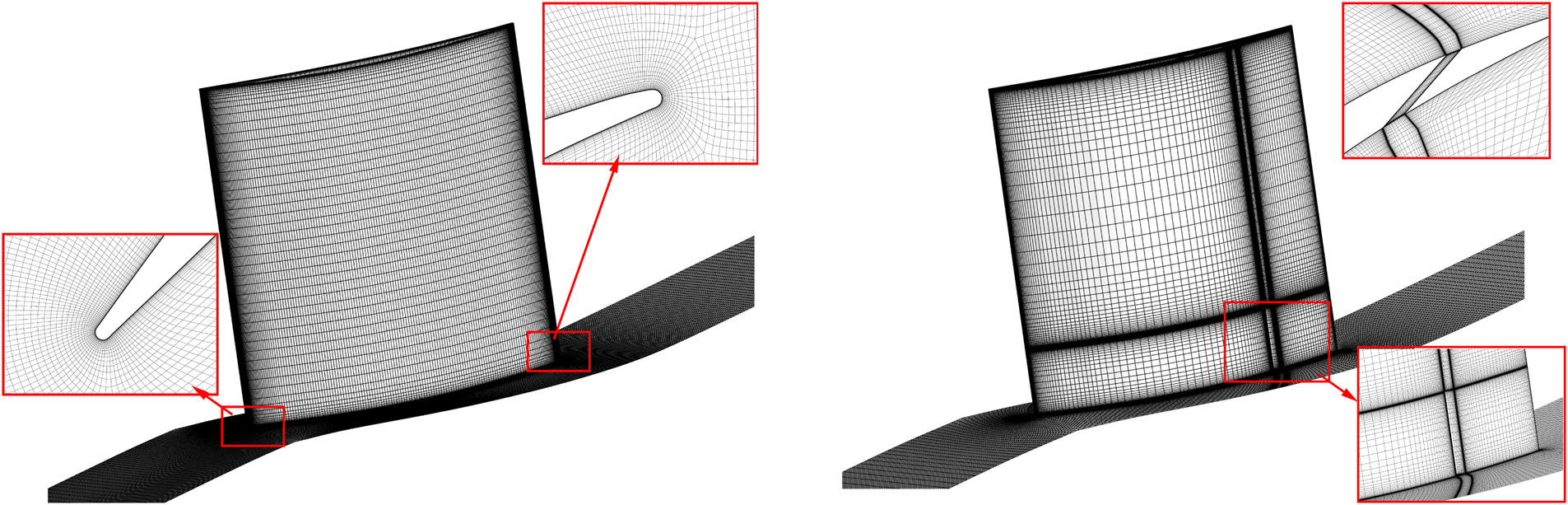
The meshes for the simulation were generated using the NUMECA Autogrid5. Figure 2 shows the meshes for datum cascade and 3D slotted cascades. The structured multi-block O4H grid was used for the datum blade. For quasi-2D and 3D datum cascades, a series of grids with different densities and distributions were compared with guarantee grid independence. The final grid for the datum blade has 2.3 million grid points with 77 nodes in the spanwise direction. A H-block grids was added for the slot on the basis of the datum blade mesh. About 0.12 million grid points were chosen, which satisfies grid independence. The meshes were added to the main flow passage to ensure the one-to-one correspondence of the mesh nodes at the junction and optimize the local mesh expansion ratio (mainly for the boundary layer mesh in slot). The final grid for the slotted blade has 3.8 million grid points. The y+ calculated was less than 1 for all simulations.
Validation of simulations
Comparisons were made between test results and simulation results. The total pressure loss coefficient
Figure 3.
Comparison of total pressure loss coefficients (left) and static pressure coefficients (right) between test and CFD of datum cascade.
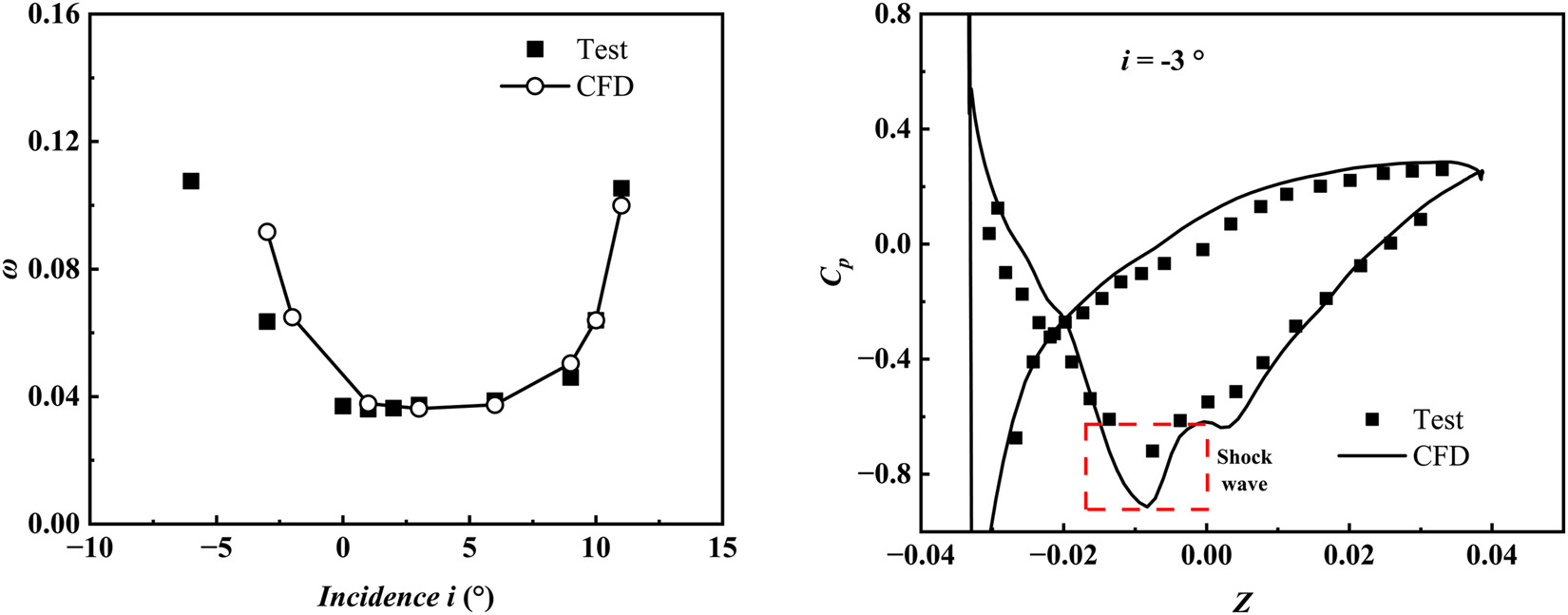
Within positive and negative stall boundaries (twice the minimum loss conditions) except for the incidence angle of −3 deg, the deviations of total pressure loss
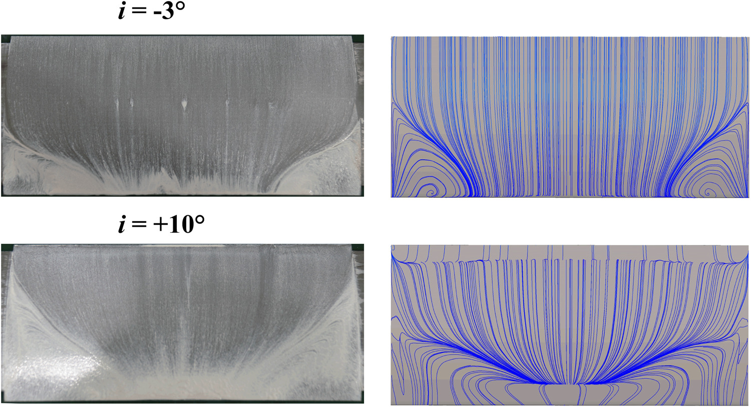
The intensity of the shock wave in the simulation result is greater than the test results. The difference in the loss when incidence angle is −3 deg was mainly produced in the shock wave. The streamlines on blade surface of test and simulation were also compared in Figure 5. The simulation of different incedences can well predict the region of separation. Based on the above comparison, simulations in this paper are reliable.
Results and discussions
Mid-span performance
For cascade test, the performance at mid-span was of interest. In order to obtain the performance of the 2D profile in test, the flow and performance at mid-span of cascade should be closer to the 2D results. Figure 6 shows the total pressure loss
Figure 6.
Performance varying with incidence at mid-span (left: total pressure loss, middle: deviation angle, right: AVDR).
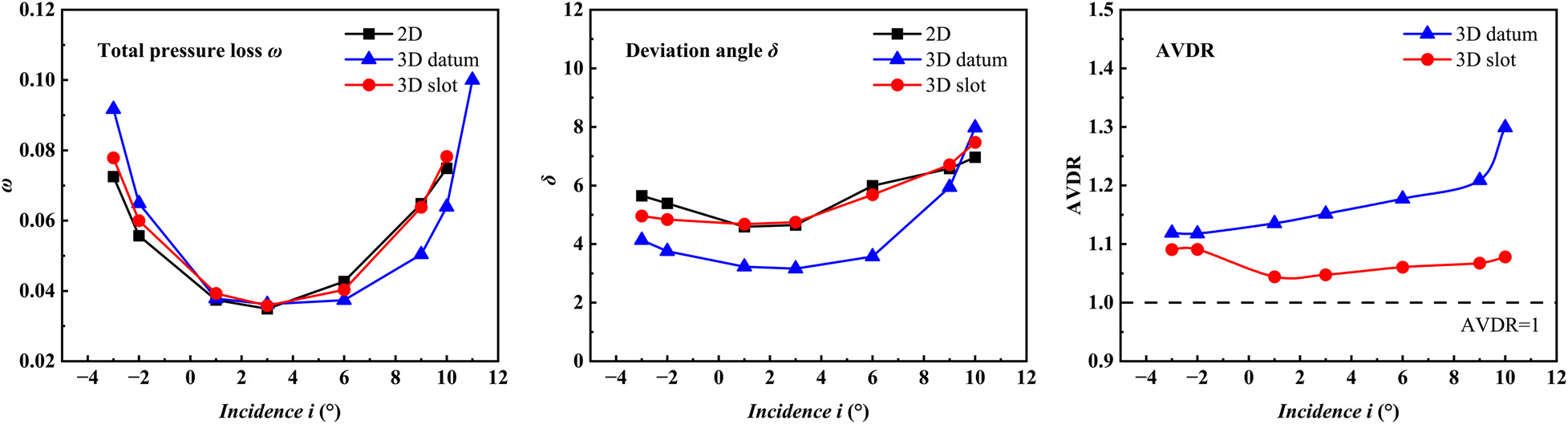
The slotted cascade better predicts the performance of the 2D profile compared to the datum cascade. When
Figure 6 also shows the changes in AVDR under different incidence angles. AVDR is defined by Equation (3), in which
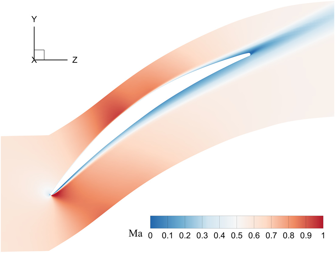
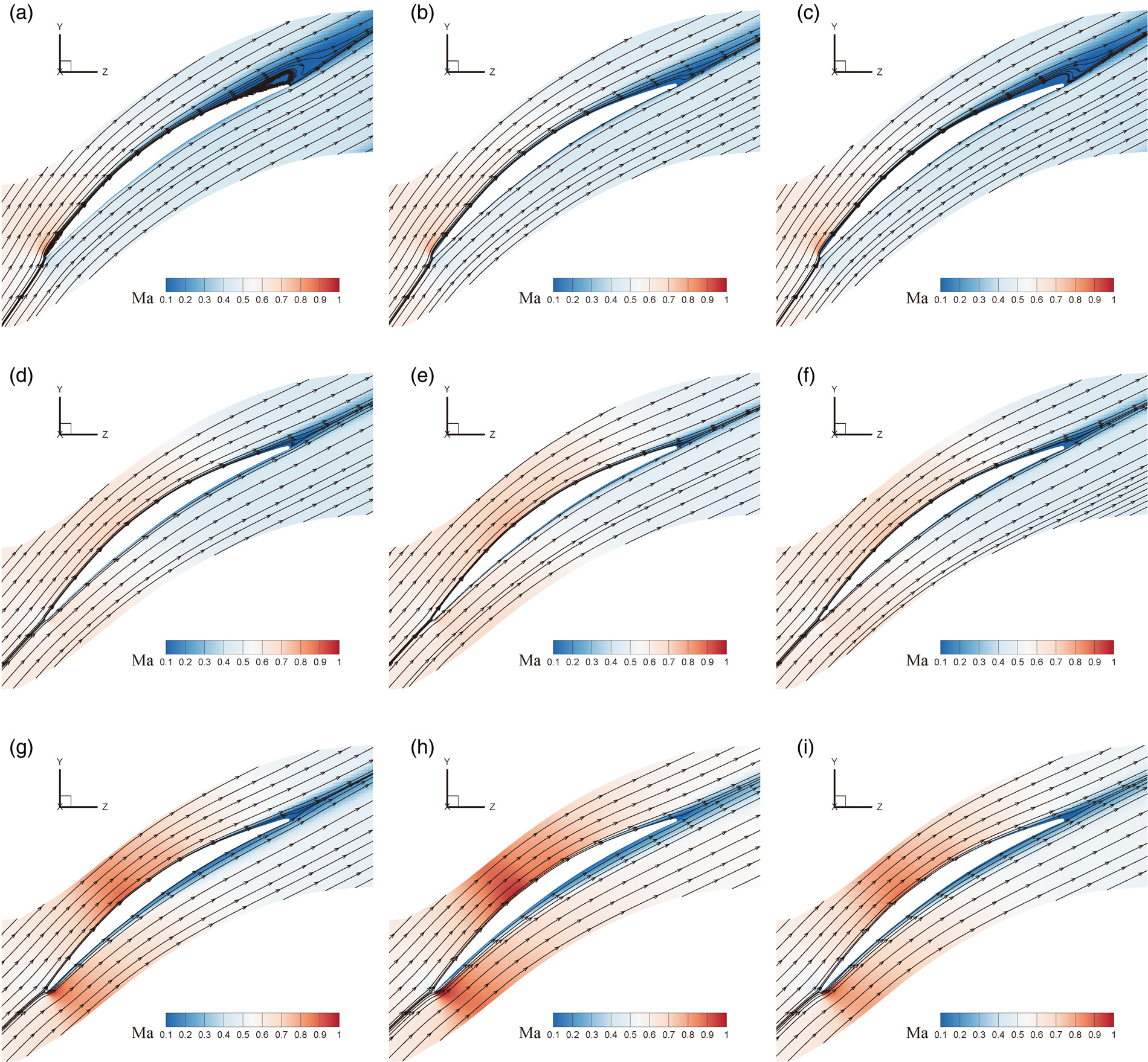
Streamlines and Mach number contours at mid-span at typical incidence angles are compared in Figure 7, to analyse the effect of slotting on the flow in the cascade. The results show that the flow of the slotted blade in the blade is closer to the 2D profile flow. When
Figure 7.
Mach number contours and Streamlines under typical incidences: (a) 2D, +9 deg, (b) datum, +9 deg, (c) slot, +9 deg, (d) 2D, +1 deg, (e) datum, +1 deg, (f) slot, +1 deg, (g) 2D, −3 deg, (h) datum, −3 deg, (i) slot, −3 deg.
Comprehensively, blade end slot on cascade reduces the AVDR, restores the flow in cascade to 2D flow, and better predicts the performance of the 2D profile.
3D flow structures
The three-dimensional flow structure of datum cascade and slotted cascade when
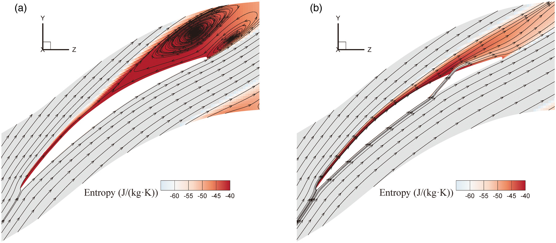
Figure 9 shows the pressure gradient contours and streamlines on the blade and end wall surfaces, reflecting the flow and separation on the wall. The pressure gradient in the blade height direction (X direction),
Figure 9.
Pressure gradient contours and Streamlines on blade surface and end-wall when incidence is +9 deg (a) datum, (b) slot.
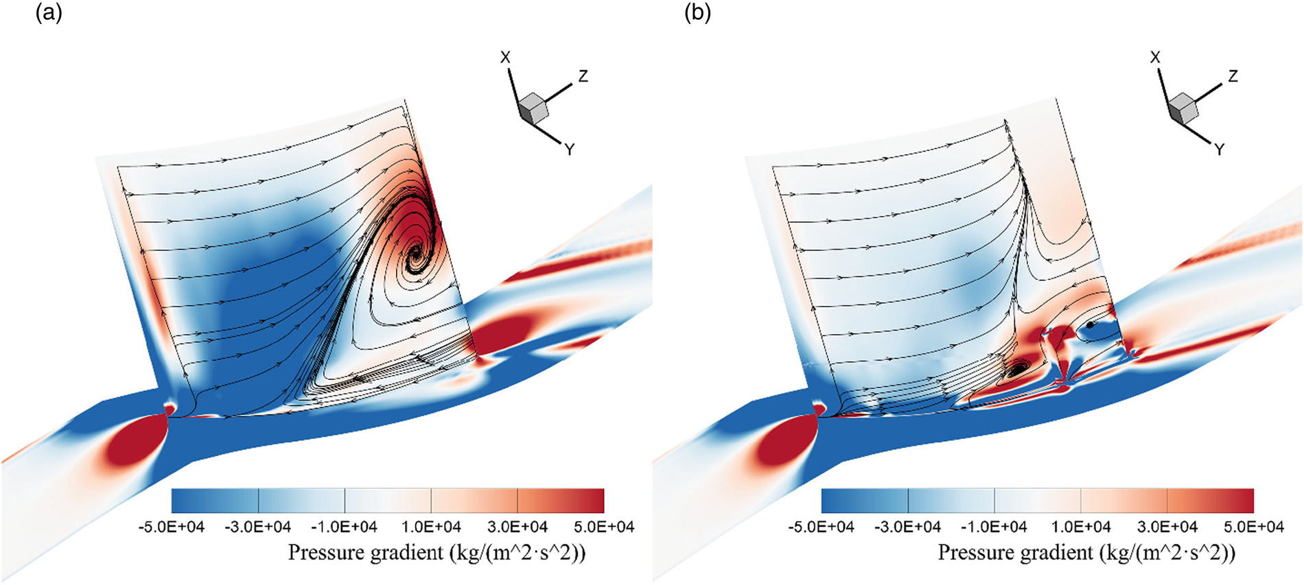
Corner separation occurs in the corner near the suction surface of the datum cascade. Driven by the positive pressure gradient in Y direction on the end-wall near the trailing edge, the end-wall boundary layer mixes with the trailing edge separation, forming a backflow near the end-wall at outlet and blocking the flow. The blockage causes a large negative pressure gradient in X direction on the front blade surface, pushing the incoming flow upstream to move toward the mid-span starting from the position about 40% of the chord. Finally, the flow channel at mid-span is squeezed.
The slot jet of the slotted cascade changes the three-dimensional flow in the corner. The jet changes the positive pressure gradient in Y direction at the end-wall, pushing the low-energy fluid away from the blade surface and relieving the blockage of the slot outlet and its downstream. The newly formed separation upstream of the slot outlet is suppressed by the jet, failed to form a large separation. The separation in the corner zone is suppressed, which reduces the blockage in the end-wall. The upstream flow is driven by less pressure difference toward the mid-span, and the flow is squeezed less. Since the flow is not significantly accelerated, a large trailing edge separation reappears at mid-span, which is the flow phenomenon that should appear in two-dimensional flow of this profile.
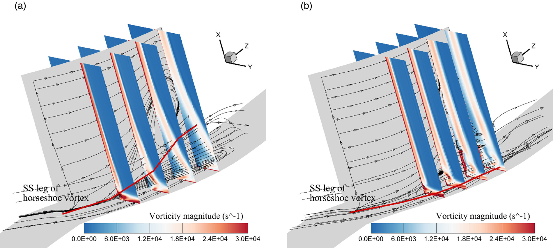
Vorticity magnitude contours and 3D streamlines for different S3 stream surfaces are shown in Figure 10, and the development of vortices in the blade passage can be observed. In the datum cascade, the suction surface leg of horseshoe vortex begins to move upward at position about 40% of the chord, and is drawn into the trailing edge separation. The end-wall boundary layer is involved in the separation and flows back downstream of the trailing edge, aggravating the blockage. The low-energy fluid in the corner area continues to accumulate, forming corner separation covering ranges about 35% span. In the slotted cascade, upstream of the slot outlet, the horseshoe vortex also moves upward to form a local vortex. However, it is pushed away from the blade surface under the impact of the slot jet, and then flows downstream along the mainstream direction after being accelerated. Near 10% span, that is, at the upper end of the slot, the slot jet flow is small. It separates and mixes with the trailing edge boundary layer to form a new separation. Since this separation is caused by the disturbance of the slot jet to the trailing edge separation, the separation range is small and the location is close to the downstream, so it has little impact on the flow above 20% span.
Figure 10.
Vorticity magnitude contours on S3 stream surfaces and 3D Streamlines when incidence is +9 deg (a) datum, (b) slot.
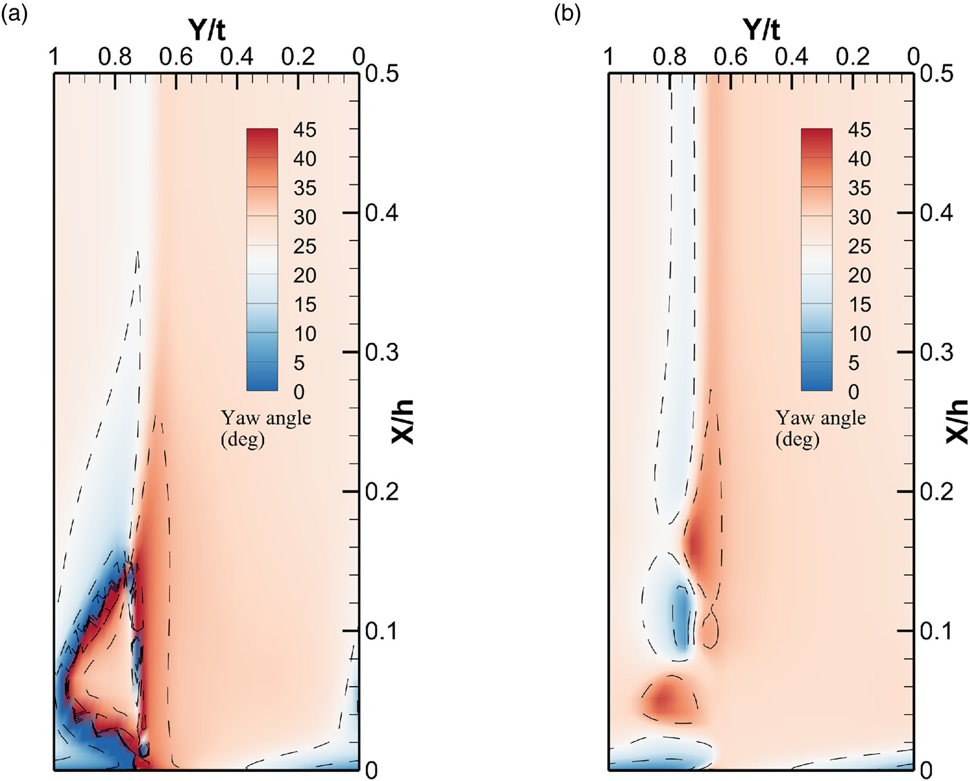
The yaw angle is resolved by the arc tangent ratio of the circumferential velocity to the streamwise velocity.
Figure 11 shows the yaw angle contours of the S3 stream surface at 20% chord downstream of the trailing edge. In the corner area of the datum cascade, a recirculation zone covering about 15% span appears, and a narrow trailing edge separation occurs above 20% span. In the corner area of the slotted cascade, the original separation area disappears and two new separations appear. The passage vortex formed between the suction surface leg of horseshoe vortex and the end wall boundary layer near the end wall (below 5% span). Due to the push of the slot jet, the passage vortex fails to mix with the trailing edge separation and fails to develop upward along the blade surface. The slot jet and trailing edge boundary layer form a vortex at about 10% span. The two separations failed to mix and develop under the splitting of the slot jet. Above 20% span, a wide trailing edge separation appears, which is the trailing edge separation of the 2D profile at this incidence
Conclusions
In this work, a novel method for cascade tests, blade end slot, was proposed to make test results better reflect the performance of two-dimensional profile in a highly loaded compressor cascade. Through the calculation results of 2D and 3D CFD, the performance and three-dimensional flow structures of the 2D profile, 3D datum cascade and slotted cascade were compared and analysed. The results show that blade end slot is a feasible test method. Conclusions are as follows:
Blade end slot reduces the AVDR of the cascade and weakens the flow acceleration in the mid-span. The trailing edge separation at mid-span of the cascade increases under positive incidence angle and the compression wave weakens under negative incidence angle, which is closer to the flow of a two-dimensional profile. The slot designed in this work covers 10% span near the end-wall and the slot outlet is at position of 80% chord. This solution reduces the deviation of performance between 3D cascade and 2D profile. In positive incidence conditions, which are more dangerous to operation, the relative deviations of total pressure loss are less than 5%, and the errors of deviation angle are less than 0.5°.
The slot jet brought by the slotted cascade controls the corner separation and reduces blockage near the end-wall. The jet pushes the suction surface leg of horseshoe vortex and the end-wall boundary layer away from the blade surface, hindering further development of separation. At the same time, the jet accelerates the low-energy fluid near the trailing edge at the end wall to flow downstream, preventing the fluid from forming a backflow in the corner area. Two new separation zones are formed at the outlet of the cascade, the separation area and blockage are smaller than the corner separation of the datum cascade.