
Introduction
The political goals of limiting the effects of climate change from the Paris Agreement, in general, and from the Flightpath 2050 published by the European Commission (European Commission, 2011) for aviation, in particular, can only be achieved by reducing
Numerous electrified powertrain topologies have been identified for different passenger capacity and flight range requirements (Jansen et al., 2017; Arzberger, 2021), some of whom include different types of fuel cell systems (FCSs). These FCSs are intended to provide electric power to electric motors, which drive the propulsors of the aircraft, by consuming hydrogen. Electrified powertrain topologies can be categorised in turbo-electric, all-electric and hybrid-electric topologies (Sahoo et al., 2020). Turbo-electric topologies utilise a generator driven by a gas turbine to provide electrical energy to electric motors. In full turbo-electric topologies all propulsors are driven by electric motors, while in partial-turbo-electric concepts at least one propulsor is also driven by a gas turbine. All-electric concepts rely completely on galvanic cells, such as batteries and fuel cells, for energy supply to the electrically driven propulsors. These topologies can be solely battery-based or fuel cell-based, where the fuel cell system is generally supported by a battery. Such a fuel cell-based approach has been applied in the HY4, the first hydrogen fuel-cell powered four seater passenger aircraft (Arat and Sürer, 2017). Here, a maximum of 45 kW of electric power is provided by a polymer electrolyte membrane FCS and 45 kW by a battery system (Kaptsov and Rodrigues, 2021). Hybrid-electric topologies utilise a combination of gas turbines and galvanic cells to provide energy to the propulsors. Here, fuel cells can be included and synergies with the gas turbine compressor and turbine system could be utilised. Hybrid systems using solid oxide fuel cells have been investigated for utilisation in aircraft auxiliary power units (APUs) up to 120 kW (Sahoo et al., 2020). To comply with the strict requirements in aviation, for instance concerning reliability, safety and weight, numerous challenges concerning air, fuel, water and thermal management have to be solved. Hence, FCSs have not been applied in commercial aviation yet.
This paper presents an overview of the most relevant fuel cell types, evaluates them and identifies the most promising options for application in commercial electrified aircraft propulsion. First, the most common fuel cell types and the evaluation methodology are presented. Subsequently, evaluation criteria are derived from aviation-specific requirements. Based on these criteria, the fuel cell types are evaluated by means of a weighted point rating for application in aircraft propulsion and respective design challenges are identified.
Fuel cells
In general, a fuel cell (FC) is an electrochemical cell in which electrical energy is converted from the chemical potential of the fuel by encouraging a pair of redox reactions, a reduction and an oxidation reaction. In order to eliminate
Polymer electrolyte membrane fuel cells
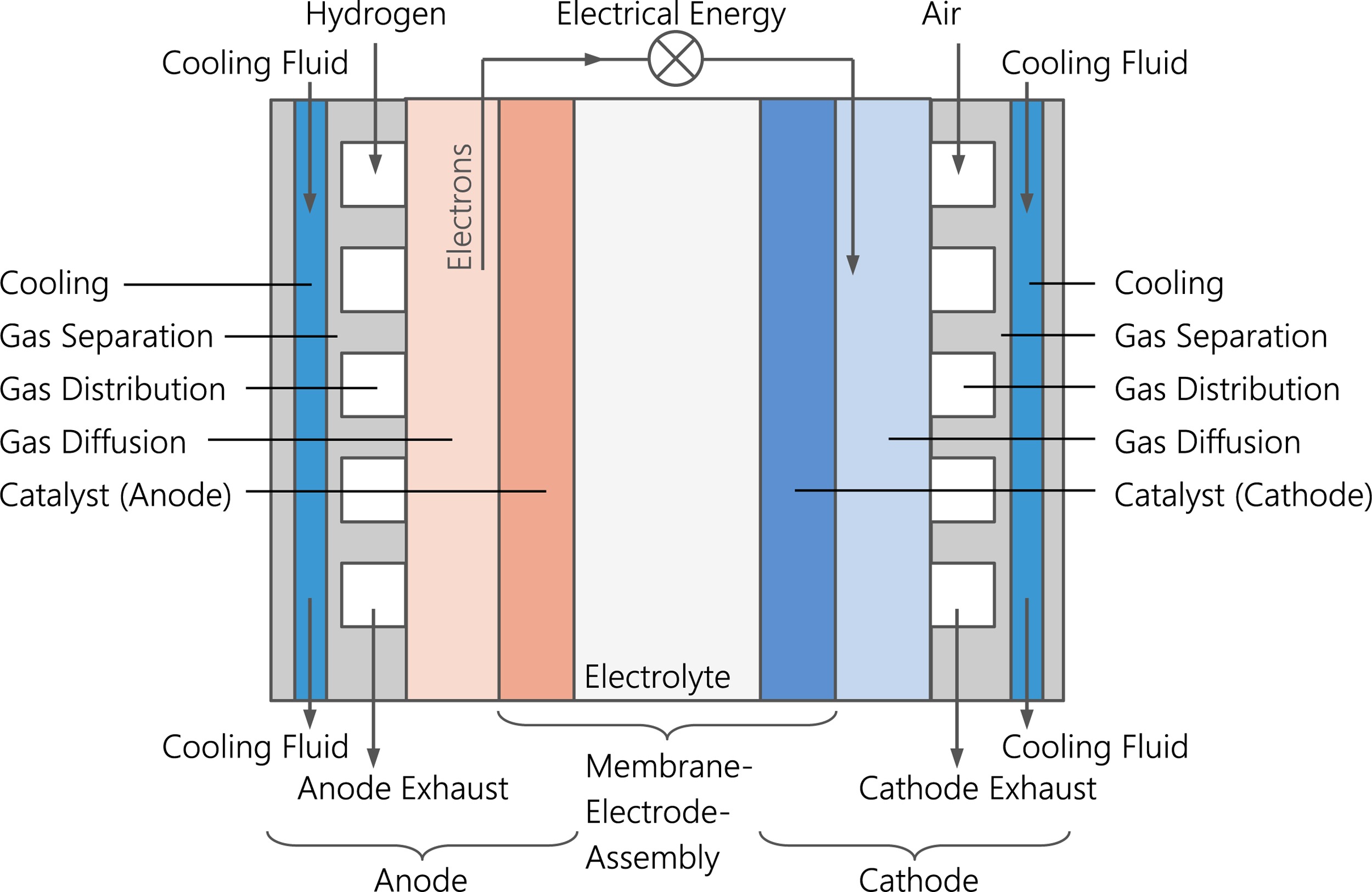
Fuel cells consist of two electrodes, which are separated by an ion-conduction medium, an electrolyte. In accordance with its name, a sulfonated polymer membrane, typically NafionTM, is used as electrolyte for low-temperature PEMFC (LT-PEMFC) applications (Peighambardoust et al., 2010; Schalenbach et al., 2015). The electrodes consist of gas diffusion layers (GDL), containing carbon-based fibre or paper. Each electrode must be coated with a catalyst to initiate the electrode reactions (Li et al., 2009). Therefore, it is manufactured in such a way that the catalyst, the electrolyte and the fuel or the oxidizer enter into a three-phase contact (Dicks and Rand, 2018). Together, they form the so-called membrane electrode assembly (MEA), as shown in Figure 1 (Kakati and Deka, 2007; Töpler and Lehmann, 2017).
The structure of a PEMFC and where the reactions take place is illustrated in Figure 2a). The oxidation reaction (I) is encouraged at the anode liberating electrons
Figure 2.
Working principle of relevant fuel cell types. (a) PEM fuel cell (b) Alkaline fuel cell (c) Direct methanol fuel cell (d) Phosphoric acid fuel cell (e) Molten carbonate fuel cell (f) Solid oxide fuel cell.
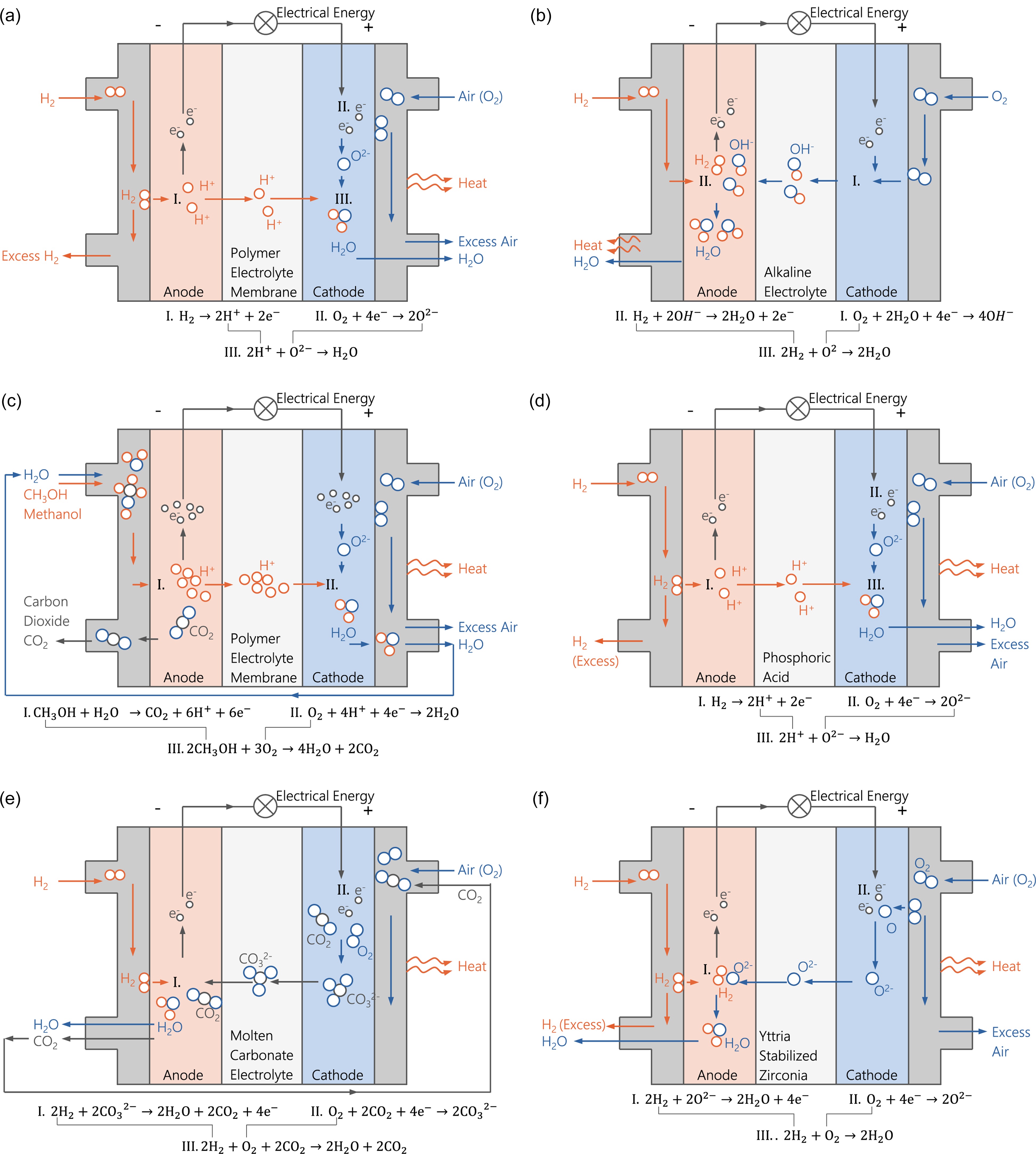
Based on the elementary redox reaction (III), the product and reactant streams are determined. The energy released during this conversion is equal to the Gibbs free energy
By arranging multiple cells in series to form a fuel cell stack, the voltage of an FCS can be increased. About 300–450 cells can be connected and as a consequence a maximum power of 60–100 kW at 1,500–2,000 W/l can be achieved (Reif, 2018). The neighbouring FCs in a fuel cell stack must be structurally and electrically connected to each other, while their respective reaction gases need to be separated. Bipolar plates are used for this purpose. These can account for up to 80% of the mass and 38–45% of the cost of the stack (Kakati and Deka, 2007). Bipolar plates have both a positive cathode-side pole and a negative anode-side pole. Furthermore, they contain the two GDLs, two gas separation layers and a cooling layer (Töpler and Lehmann, 2017), as shown in Figure 1. Additional mechanical and electrical components (Balance of Plant, BoP) are required for automated and optimised operation of a LT-PEMFCS. In particular, air and fuel supply system, humidifier and cooling system as well as controls and sensors are necessary (O’Hayre et al., 2016).
The LT-PEMFCS provides high power density compared to other FC types. However, about 40–60% of the chemical energy is converted into heat and therefore large amounts of heat need to be removed from the FCS. Especially for the LT-PEMFC, whose operating temperature is ideally close to 80° C with only small acceptable temperature gradients within the stack, large heat exchanger units are required. Moreover, an electrolyte, such as NafionTM, requires humidification of the membrane of around 30% in order to achieve optimal operating conditions (Mehta and Cooper, 2003; Lehmann and Luschtinetz, 2014). As a consequence, water management and humidification subsystems become necessary, leading to an increased system complexity.
Sustaining ideal conditions for the MEA is highly critical for its durability and reliability, as dehydration and humidity cycling can lead to mechanical fatigue or chemical attacks by peroxide radicals. In particular during transient operation, this is a major challenge and leads to shortened membrane life. Hereby, the otherwise very good dynamic behaviour can be significantly limited depending on the application.
High-temperature polymer electrolyte membrane fuel cells
The working principle, structure and chemical reactions of the high-temperature PEMFC (HT-PEMFC) are identical to that of the LT-PEMFC. However, higher operating temperatures between 130 and 180° C can be achieved by using other types of electrolyte membrane (Jiang and Li, 2022). In HT-PEMFCs, the most common variants are polybenzimidazole membranes modified with phosphoric acid (phosphoric acid-doped polybenzimidazole, PA/PBI) (Kurzweil, 2016; Rosli et al., 2017). Alternative high-temperature membranes are being investigated on an ongoing basis, such as those based on highly crosslinked fluorinated ethylene-propylene copolymers or on ceramic diaphragms (Kurzweil, 2016). The HT-PEMFC is also considered as a hybrid of the LT-PEMFC and the phosphoric acid fuel cell (PAFC), which combines the respective advantages in the best possible way (Peters, 2015).
One major advantage of the HT-PEMFC is that the phosphoric acid in the PA/PBI membrane takes over the function of proton transport to the cathode with the aid of hydrogen bonds (Peters, 2015; Kurzweil, 2016). Therefore, the need for humidification of the membrane via the reactant flows is removed entirely and a reduction of the system complexity can be achieved (Kurzweil, 2016). In addition, HT-PEMFCs could potentially allow for the use of cheaper and more accessible catalyst materials, such as iron and cobalt instead of platinum (Kurzweil, 2016). Furthermore, for the same amount of heat to be dissipated the necessary cooling surface area could be significantly reduced due to the higher operating temperature, which in turn results in a significantly lower system mass (Peters, 2015; Jiang and Li, 2022). On the other hand, higher temperatures lead to increased thermal, chemical and structural stresses (Jiang and Li, 2022). While the tolerance towards impurities in the reactant gases is better than in LT-PEMFCS, the use of the phosphoric acid is accompanied by potential risks of acid leakage as well as lifetime and durability issues (Kurzweil, 2016). In combination with reformed methanol without additional purification steps, the HT-PEMFC could also address compact alternative application needs (Araya et al., 2016; Rosli et al., 2017; Jiang and Li, 2022).
Alkaline fuel cells
Alkaline lyes are aqueous solutions of metal hydroxides. The electrolyte primarily used in an alkaline fuel cell (AFC) is potassium hydroxide, a caustic aqueous solution of potassium hydroxide
The resulting reaction water can either be discharged at the anode or removed via a purification cycle of the electrolyte (Dincer and Zamfirescu, 2014). The former variant is known as fixed electrolyte, while the latter is known as mobile electrolyte (Kurzweil, 2016). The purification cycle can be used to remove impurities and heat from the electrolyte in addition to the reaction water (Dincer and Zamfirescu, 2014). With the reaction water sufficient amounts of heat are removed from the system, so that no additional cooling is required (Schulze and Gülzow, 2009). This results in higher levels of efficiency. Furthermore, AFCs have been extensively used in aerospace, e.g. the Apollo missions, and have shown to be of simple build and robust nature (Kurzweil, 2016).
The supply of pure oxygen or at least
Direct methanol fuel cells
In direct methanol fuel cells (DMFCs), the chemical energy of the fuel, methanol,
However, instead of pure
A major disadvantage of DMFCs is the inevitable by-product of
Phosphoric acid fuel cells
The build and working principle of the phosphoric acid fuel cell (PAFC) is very similar to that of the PEMFC, as can be seen in Figure 2d). Furthermore, the redox reactions (I) to (III) are identical. The PAFC, however, uses phosphoric acid as electrolyte, bonded by means of a fibrous matrix of silicon carbide and fixed between the electrodes (Kurzweil, 2016). High temperatures are necessary to obtain good conductivity of the electrolyte, but above 225° C phosphoric acid loses its chemical stability (Kurzweil, 2016). The characteristic attributes of this FC type are similar to those of the HT-PEM in terms of potential for acid leakage and limited lifetime due to high chemical corrosion risks. PAFCs are also sensitive to traces of sulphur. They require close monitoring of the temperature and with that cooling.
Small amounts of
Molten carbonate fuel cells
Molten carbonate fuel cells (MCFCs) use molten alkali carbonates as electrolyte and porous electrodes made of nickel (Kurzweil, 2016). The fuel is typically pure hydrogen, but it can also be obtained from hydrocarbons, primarily methane, by an upstream or internal reformer, which is operated with waste heat from the FC. In that case, efficiencies of up to 60% can be reached. Another variant of the MCFC exists that utilises carbon monoxide as fuel (Kurzweil, 2016). In the hydrogen-fuelled option,
Its high operating temperatures (600–650° C) make the MCFCS suitable for CHP application and the utilisation of small heat exchangers, while significantly reducing its durability (Kurzweil, 2016).
Solid oxide fuel cells
Solid oxide fuel cells (SOFCs) primarily use yttrium-stabilised zirconia as electrolyte and hydrogen as fuel supplied to the anode (Kurzweil, 2016). As in the MCFC,
The biggest advantages of the SOFC are that it operates without triple phase boundaries, humidification, or the complex carbonate recirculation of the MCFC (Kurzweil, 2016). Furthermore, it displays a high tolerance level with regards to the sulphur content and can be operated with different fuels at a very high efficiency of 60 to 65% on cell level (Kurzweil, 2016). Due to the high temperature level, opportunities for heat recovery and CHP arise (Jiang and Li, 2022).
However, start-up times for SOFC are comparably long and challenges arise with regards to sealing, controls and lifetime (Jiang and Li, 2022). Recent developments are aiming towards lowering the operating temperatures to the medium temperature range of about 500° C, which would enable significant improvements in terms of service life, material cost and reliability (Jiang and Li, 2022).
Evaluation
Methodology
There are numerous evaluation methods for technical products with a wide range of complexity and for different decision tasks. The purpose of these methods is to assist in the decision-making process in the most objective way possible when making a selection from several potential solution options. Additionally, evaluation methods can assist the risk identification and provide decision traceability (Feldhusen and Grote, 2013).
The most objective evaluation can be achieved by using formal evaluation methods. However, the numerical results should not be the sole basis for a decision. Rather, the methods should encourage an intensive examination of the evaluation to be able to make a holistic judgement (Ehrlenspiel et al., 2014). The assessment should be carried out by a group of people from different engineering fields to obtain a wide range of expertise, thus ensuring the best possible objectivity (Lindemann, 2009; Ehrlenspiel et al., 2014). The procedures of most evaluation methods follow a similar structure (Kazula, 2022), as shown in Figure 3. Throughout the entire product development process, the application of evaluation methods is useful and necessary. During the conceptual phase, the evaluation contributes to the basic orientation within the design space. In later phases, a comparative evaluation of several concepts is carried out to select the most suitable solution (Feldhusen and Grote, 2013). A differentiation is made between simple, elaborate and complex methods, whereby it is not generally advisable to use complex and time-consuming methods (Feldhusen and Grote, 2013). The method should be chosen according to the complexity of the decision task and the time available. Widely known methods are the advantage/disadvantage comparison, the selection list, the simple point rating, the weighted point rating, the technical-economic evaluation according to VDI guideline 2225, and the cost-benefit analysis (Verein Deutscher Ingenieure, 1997; Lindemann, 2009; Feldhusen and Grote, 2013; Ehrlenspiel et al., 2014).

A weighted point rating is used to rank the fuel cell options for aviation in this study due to its preliminary nature and presents a good starting point for future investigations. Hereby, the identified criteria are weighted according to their significance to the success of the product. The weighted point rating is the foundation of other quantitative methods such as the preference matrix and the cost-benefit analysis (Lindemann, 2009). The advantages of this method are that it is universally applicable, easy to use and can be implemented within a short period of time. For the successful implementation of this method, comprehensive knowledge of the properties of the solution options is required.
Evaluation criteria
The weighted point rating as a quantitative evaluation method requires the differentiation of the individual criteria, although these criteria are often interrelated and have an impact on each other. For instance, a weight reduction can be achieved by using lightweight materials, which usually entail higher material cost. Moreover, increased fuel requirements due to low efficiency result in additional weight. Furthermore, components with long service life and high power density tend to have high unit cost. For fuel cells in aviation, the most important evaluation criteria can be derived from the aircraft propulsion system requirements document. These criteria are efficiency and performance, weight, ease of integration, safety, reliability and life cycle cost, as well as development and manufacturing cost.
Efficiency and performance
The efficiency
Weight
The power density and thereby the weight of an FCS is determined by the density and strength properties of the utilised materials, operating resources, additionally required system components, as well as potentially necessary safety adjustments, e.g. bulkheads, grounding and breakout panels. Hereby, material choices and functional integration have a huge impact on the system weight. Moreover, the resulting system mass is also largely driven by the operating temperature, as it determines the dimensions of the required heat exchanger and cooling systems. Further required system components can be reformers, compressors, filters, pipes, sensors and wiring. Additionally, batteries can be necessary to assist cold start, restart and start-up, as well as peak power demands. The main operating resource is the fuel, e.g. hydrogen or sustainable aviation fuel, whereby the gravimetric power density has to be considered. Further operating resources and consumables can be purging fluid, cooling fluid, electrolyte, water and oxidant.
Ease of integration
The ease of integration of an FCS is defined by the required installation space of the system components, as well as, interfaces and interactions within the FCS, of the FCS with other components of the electrified powertrain, e.g. power electronics or wires, and of the FCS with components its vicinity. These interactions are investigated best by conduction of a Zonal Safety Analysis (ZSA), which is part of a Common Cause Analysis (CCA) (SAE Aerospace, 1996).
For instance, hot surfaces of certain FCSs combined with flammable fluids can cause fire in case of leakage. The mitigation of this risk requires design precautions, e.g. ventilation, drainage and potentially the integration of fire walls, fire detection, as well as an extinguishing system. Leakage of hot air or other fluids in proximity to electrical equipment of the adjustment system or sensors can cause damage to these components (Kritzinger, 2016). Consequently, over pressure breakout panels, ventilation, drainage and heat protection for power electronics, e.g. by means of bulkheads, could become necessary. Electric components must be protected from damage by grounding, integration of drainage and waterproof component casings (Kritzinger, 2016). Thermal expansion can cause high stresses, friction and even damage in rigid wires and pipes of the FCS. Hence, a flexible design of wiring and pipe installation to minimise stresses as well as a minimum clearance between each other to avoid friction can be required.
The utilisation of FCSs with high operating temperatures can also result in a necessity for innovative high-temperature heat exchangers made of ceramic materials. Furthermore, additional sealing, air and fuel filters, pressure management, as well as recirculation of water, carbon dioxide or electrolytes can result in increased integration efforts.
Safety
The main function of the FCS as part of the electrified aircraft powertrain is to provide electrical power to the propulsors. Furthermore, electrical power is required for board electrics, avionics, cabin air pressurising and potentially in ice protection systems and thrust reverser units. The FCS could also be utilised to fulfil heat supply functions, e.g. for ice protection purposes. No hazardous events should occur due to the FCS or a malfunction of that system.
Potential safety hazards are electromagnetic interference, damage to components in the proximity, fire and explosions. Electromagnetic interference could occur due to insufficient electromagnetic compatibility and shielding. Damage to components in the proximity can be caused by high operating temperatures and leakage of fluids, e.g. hydrogen, pressurised air, acids and bases. Fires could result from combinations of hot surfaces and leakage of flammable fluids.
Reliability and life cycle cost
Service life, reliability and life cycle cost of FCS are closely associated. Reliability is mostly based on the system complexity, the resulting number of parts and the necessary accessories, e.g. sensors and means for cold start, restart and start-up. The lifetime of the utilised materials is also an important factor and defined by the ability to withstand thermal, chemical strains, as well as mechanical fatigue and limit loads. Furthermore, moisture can lead to corrosion, while sand and dirt can block fluid paths and valves. Moreover, chemicals, e.g. hydrogen and acids, can significantly influence the lifetime of the utilised materials. The life cycle cost of an FCS is additionally influenced by its fuel consumption, further necessary consumables, e.g. purge fluids, as well as maintenance intervals and efforts. Hereby, robust design can increase maintenance intervals and hence reduce costs. Furthermore, fuel consumption can increase due to decreased efficiency of rapidly deteriorating system components, such as the catalysts and the electrolyte membranes.
Development and manufacturing cost
The development cost of an FCS for application in aviation is mostly based on its TRL and previous exposure to aviation applications. A low TRL requires increased development efforts. Little experience concerning a certain FCS type and the utilised materials demand for more analyses and tests. However, FCS types with a low TRL for aviation can offer a higher potential for innovation and technological development, e.g. concerning increased lifetime and power density. Increased development cost and time are associated with those types of FCS. Moreover, innovative materials, noble metals, rare-earth elements, special manufacturing methods, additional quality controls, as well as increased required assembly and transport efforts can result in higher manufacturing cost. By using sustainable and recyclable materials, manufacturing cost can be reduced in the long run.
Criteria weighting
The weighting of the criteria is obtained by pairwise comparison (Lindemann, 2009). Hereby, all criteria are cross-checked in pairs by the evaluation group (Feldhusen and Grote, 2013). If a criterion appears to be more important than the one it is compared to, then it is evaluated with the value 2. If both criteria are equally important, they are evaluated with 1. If a criterion is less important than the one it is compared to, then it is valued with a 0.
Variations of this evaluation method also exist in which other values are assigned, for instance to distinguish whether the fulfilment of one criterion tends to be much more important, more important or slightly more important than that of the other criterion (Lindemann, 2009). This can be useful in the final phases of product development, in which a high level of detail is already available in the design, in order to enable a more detailed assessment (Pahl et al., 2007). During early phases of product development, such as in this study, this kind of evaluation cannot be performed in a fully objective manner, due to the lower degree of concretisation (Pahl et al., 2007).
After all criteria have been compared with each other, each criterion i has a total value
Table 1.
Criteria weighting via pairwise comparison.
The pairwise comparison has been conducted independently by a group of aeronautical engineers. The results have been compared with literature (Sadraey, 2013) and reveal that “safety” and “efficiency and performance” are the most important criteria for application of FCS in aviation, followed by reliability and life cycle cost, as shown in Table 1.
Fuel cell type rating
For each fuel cell type
The early low TRL of some FC types for application in aviation allows only for a comparative qualitative evaluation of the concept groups (Feldhusen and Grote, 2013). Hence, a narrow scale range of 0 to 4 has been chosen for the evaluation. Several mechanical engineers carried out the evaluation independently based on manufacturer data, literature and preliminary safety analyses according to Aerospace Recommended Practices (ARP). This way, an increased degree of objectivity is ensured (Feldhusen and Grote, 2013).
In Table 2 an intuitive description of the evaluation is enabled by utilising a plus-minus system to compare the fuel cell types against each other based their characteristics, which have been introduced in earlier chapters. The evaluation of the fulfilment of a criterion by a fuel cell type has been carried out as follows:
very good fulfilment:
good fulfilment:
average fulfilment:
bad fulfilment:
very bad fulfilment:
Table 2.
Evaluation of relevant fuel cell types on system level.
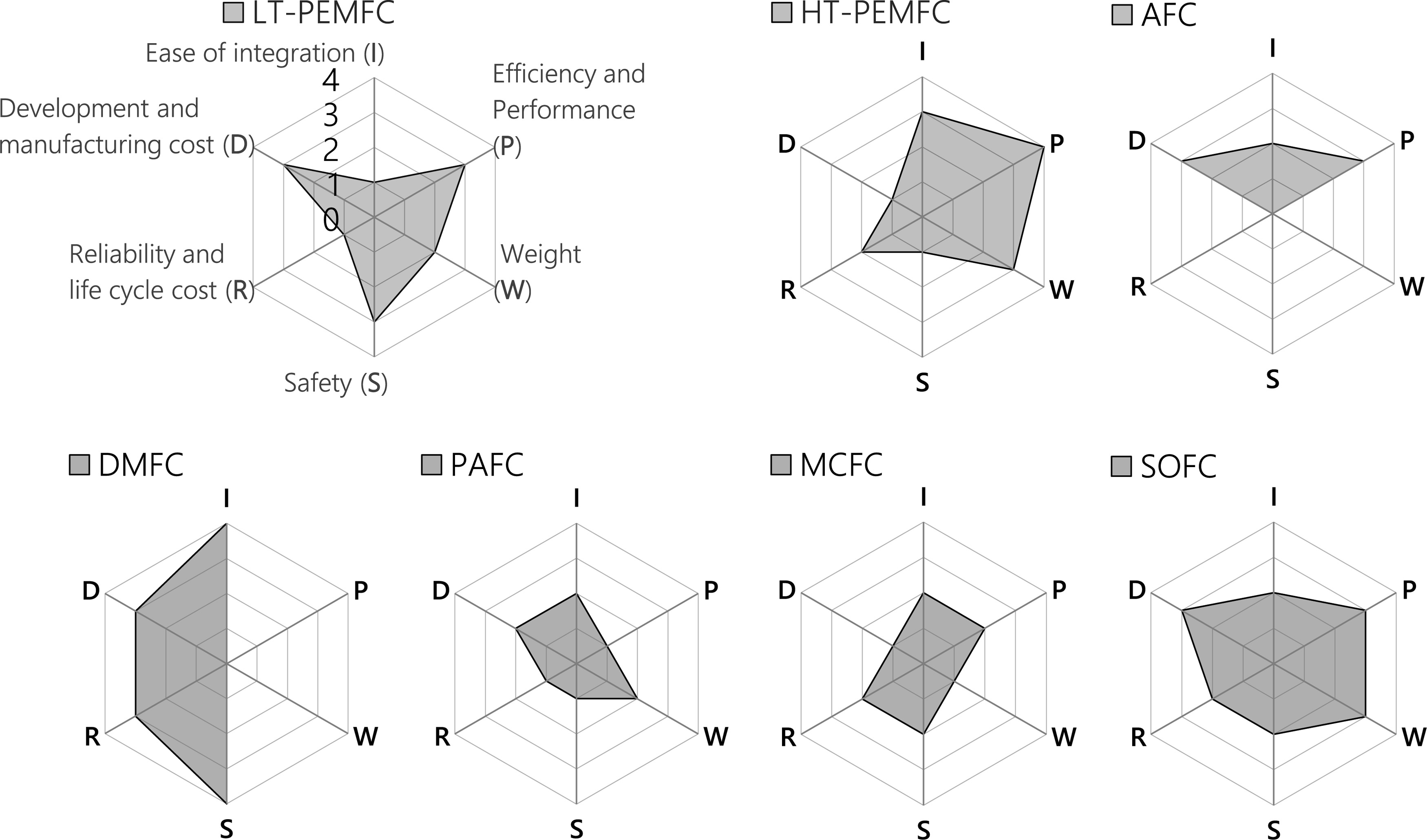
The relative rating
The SOFC has the highest relative rating
Potential and challenges of fuel cell types
The relatively low rating values highlight a huge potential for improvements of every investigated fuel cell type. In order for any FC type to become a viable option for electrified aircraft propulsion reliable solutions for providing pressurised air, for transfer of excessive heat, for reduction of weight and for increased life have to be developed.
The LT-PEMFC type has the highest TRL and was already applied in propulsion systems of small aircraft. LT-PEMFCs are complex systems, mainly due to their water management. Additionally, they require cold start support and extensive cooling, while tolerating only small temperature gradients within the stack, resulting in heavy thermal management systems. Hence, they are best suited for application in small battery-supported all-electric aircraft with low power requirements and flight altitude.
HT-PEMFC work on higher operating temperatures, and thus, require longer preheating. While also being on a much lower TRL, they offer a potentially simpler system, lower weight and increased power density compared to LT-PEMFCSs. The higher operating temperatures of HT-PEMFCSs enable smaller and lighter heat exchanger. Hence, they could be a good option for future regional aircraft.
AFC, DMFC, PAFC and MCFC are no viable fuel cell options for aircraft propulsion at this point. AFCs have a limited life and rely on pure oxygen, which results in additional fuel and storage mass, as well as risk of fire and explosions. DMFCs offer very low efficiency in combination with a fuel of low gravimetric energy density. Therefore, they require too much fuel mass for applications larger than UAVs. PAFCs have limited life due to corrosion and no positive attributes that particularly stand out. The HT-PEMFC can be perceived as having evolved from PAFC development. While being a simple system and operating highly efficient, the MCFC provides only slow start-up and bad dynamic behaviour combined with very low power density and high-temperature corrosion.
SOFCs are operated on the highest temperature level of all fuel cell types, which makes them an ideal candidate for CHP application and the utilisation of internal reforming. They offer huge potential for application in hydrogen-fuelled electrified propulsion. Moreover, in combination with a gas turbine they could enable highly efficient long-range electrified flight, while using SAFs. However, the start-up time of SOFCs is very long and the high temperatures result in high thermal corrosion and bad dynamic behaviour.
Many of the investigated aspects and properties of the respective FCSs need to be assessed further and evaluated by conducting more detailed analyses, safety and reliability studies and experiments in relevant laboratory environments.
Conclusions
The general design, operating principles and main characteristics of polymer electrolyte membrane, alkaline, direct methanol, phosphoric acid, molten carbonate and solid oxide fuel cells have been described. Evaluation criteria have been derived from aviation-specific requirements, resulting from the application of fuel cells in electrified aircraft. Based on these criteria, the presented fuel cell types have been evaluated by means of weighted point rating.
The results of this preliminary evaluation reveal the high potential for application of SOFCs, LT-PEMFCs and HT-PEMFCs. The evaluation also highlights design challenges of these fuel cell types. While LT-PEMFCs require complex thermal and water management, especially for cold start operation, HT-PEMFCs require longer preheating times and a lower TRL level. For SOFCs the start-up time is even longer as the operating temperatures are much higher. Furthermore, for all relevant fuel cell types reliable solutions for providing pressurised air, distributing excessive heat and reducing weight have to be developed.
With further progress in developing this technology for aviation, the application of fuel cell systems could enable sustainable commercial electrified flight and as a result contribute to limiting climate change.
Nomenclature
Acronyms
AFC
Alkaline Fuel Cell
APU
Auxiliary Power Unit
ARP
Aerospace Recommended Practices
CHP
Combined Heat and Power Generation
DMFC
Direct Methanol Fuel Cell
FC
Fuel Cell
FCS
Fuel Cell System
GDL
Gas Diffusion Layer
HT-PEMFC
High-Temperature Polymer Electrolyte Membrane Fuel Cell
LHV
Lower Heating Value
LT-PEMFC
Low-Temperature Polymer Electrolyte Membrane Fuel Cell
MCFC
Molten Carbonate Fuel Cell
MEA
Membrane Electrode Assembly
PAFC
Phosphoric Acid Fuel Cell
PA/PBI
Phosphoric Acid-Doped Polybenzimidazole
PEMFC
Polymer Electrolyte Membrane Fuel Cell
SAF
Sustainable Aviation Fuels
SOFC
Solid Oxide Fuel Cell
TRL
Technology Readiness Level