
Introduction
The use of carbon dioxide operating in thermodynamic supercritical conditions (sCO2) as working fluid in closed gas cycles offers the opportunity to exploit multiple classes of hot sources alternative to fossil fuels, ranging from nuclear energy to concentrated solar power and waste heat from industrial processes. Moreover, sCO2 power systems also benefit from compactness, thanks to the high density of the working fluid, which ultimately offers the opportunity for effective control of the dynamics of the plant.
A key component of sCO2 power systems is the main compressor, which is usually centrifugal due to the typical low volumetric flow rates and operates close to the thermodynamic critical point. The corresponding compression process allows for a significant reduction of the work required thanks to the liquid-like properties of CO2 in these thermodynamic conditions. However, the large departure from the ideal-gas thermodynamics (Pecnik et al., 2012; Baltadjiev et al., 2015; Ameli et al., 2018), as well as the potential occurrence of two-phase flows (Lettieri et al., 2015; Hosangadi et al., 2022; Toni et al., 2022), pose challenges in the aerodynamic design of impeller blade and meridional channel. The set-up of reliable design tools that comply with the above non-ideal effects is crucial to accelerate the development and the success of the entire technology.
Most of the studies available in the literature analyze the aero-thermodynamics of the flow within the machine or discuss the validation of computational tools for compressor flow analysis (Pecnik et al., 2012; Rinaldi et al., 2015; Ameli et al., 2018; Hosangadi et al., 2019). Only a few works focus on the design process of such non-conventional machines. Lettieri et al. (2012) redesigned a low-flow coefficient centrifugal compressor for carbon capture sequestration (vapor-like CO2). They increased the outlet impeller blade height to reduce friction losses and added a vaned diffuser to efficiently recover pressure from the resulting more tangential flow. Hacks et al. (2018) designed a laboratory-scale centrifugal compressor. The design strategy was polarized by the small-scale of the machine and the expected high windage loss. Pelton et al. (2018) investigated various design solutions to ensure a wide operating range. Ultimately, they proposed a semi-shrouded impeller with a passive recirculating casing treatment to enhance the surge margin. Romei et al. (2023) revised conventional guidelines applied to sCO2 centrifugal compressors. They suggested that designing a stage with a flow coefficient smaller than that suggested by standard design practices prevents the occurrence of two-phase flows. All these studies primarily focused on global parameters and overall machine architecture rather than detailed aerodynamic design. To address this, automatic shape optimization methods can bridge the knowledge gap regarding the appropriate design methodology for flow paths and blade shapes.
Optimization methods fall into two categories: gradient-based and gradient-free methods. Gradient-based methods converge quickly but risk getting stuck in local optima. The information of the gradient is acquired by solving adjoint equations; however, it requires a good convergence for both the flow equations and adjoint counterparts to be effective. This requirement may pose challenges in the context of sCO2 compressors, which are characterized by a complex aerodynamics involving adverse pressure gradients, near-critical thermodynamic conditions, and possible two-phase flows. An alternative is represented by gradient-free methods, which are non-intrusive and explore the global solution space but often converge slowly, making them unsuitable for time-consuming simulations. Evolutionary algorithms, such as genetic algorithms, are a class of gradient-free methods known for their ability to handle noisy and discontinuous objective functions but suffer from slow convergence. To address this, surrogate models, such as Kriging models, are employed to provide predictions for unsampled areas of the design space, allowing for thorough exploration without performing costly simulations. However, surrogate models may offer inaccurate predictions for distant designs from the sampled ones, requiring additional high-fidelity simulations to improve surrogate accuracy (Baert et al., 2020). This integration of surrogate models with evolutionary methods aims to enhance optimization cost efficiency by leveraging surrogate predictions and refining them with additional simulation data.
Examples of evolutionary surrogate-based shape optimization applied to conventional centrifugal compressors are documented by Verstraete et al. (2010) and Hehn et al. (2018). Moving to compressors for supercritical carbon dioxide applications, Romei et al. (2023) did preliminary shape optimizations modifying only the impeller meridional flow path. Recently, Ghimire et al. (2024) addressed the shape optimization of a three-stage axial compressor operating far from the critical point. However, a comprehensive stage optimization, including both meridional flow path and blade angle distribution, for centrifugal compressors operating with carbone dioxide near the critical point is currently lacking.
In the present study, we propose automatic surrogate-based shape optimizations as a means to design sCO2 centrifugal compressors. The current paper distinguishes itself from our previous work (Romei et al., 2023) by focusing on a specific application and performing systematic shape optimizations of the stage meridional and blade flow path to maximize performance, rather than providing general guidelines. The aim is to determine whether shape optimization can provide additional performance improvements starting from a well-designed stage, achieved through tailored design strategies for this application.
This work is structured as follows: at first, the baseline geometry and the CFD method to estimate compressor performance are introduced. Then, the shape optimization procedure is detailed. The optimized geometries are presented afterwards. Finally, the last section draws some conclusions and delineates prospects for future research works.
Baseline geometry
The baseline machine is a single-stage centrifugal compressor that is designed for the inlet total conditions of
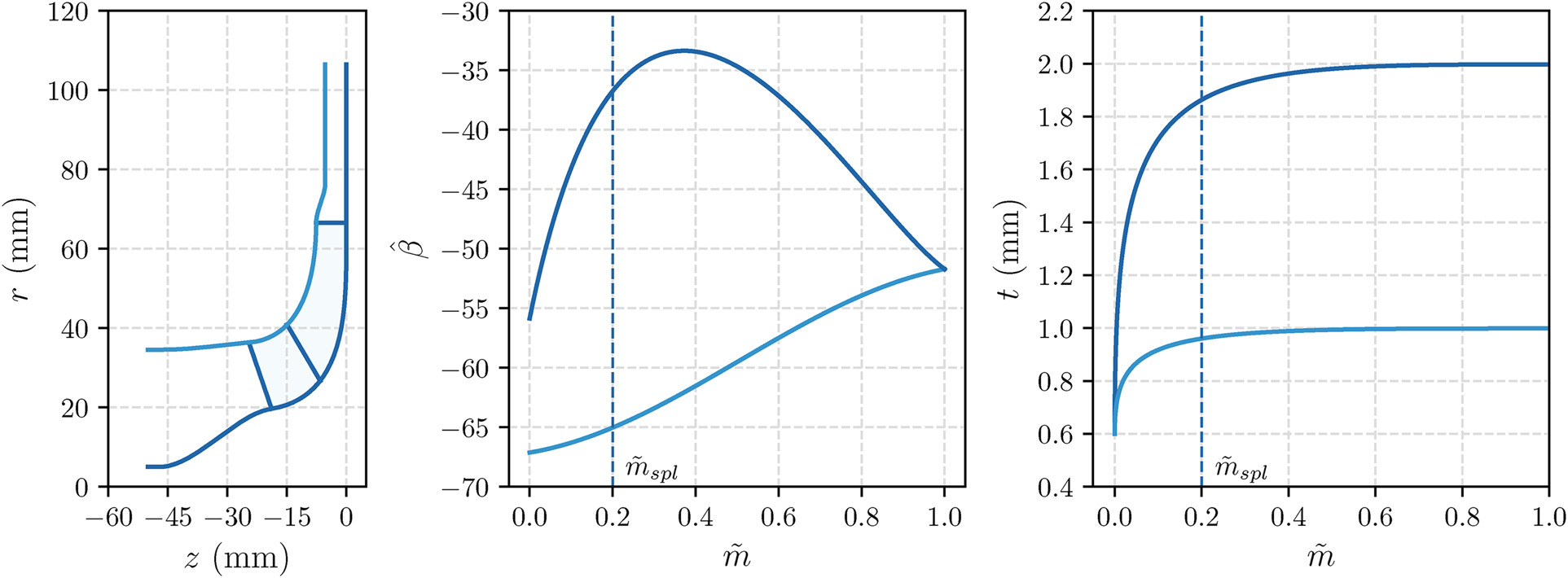
Figure 1.
Baseline impeller geometry: (left) meridional view; (middle) blade angle distribution (measured from the meridional direction, positive with rotational speed); (right) thickness distribution.
The performance estimates are determined based on steady Reynolds-averaged Navier-Stokes (RANS) simulations. The RANS equations are solved with the Ansys-CFX finite-volume flow solver, using high-order numerical schemes for both inviscid and viscous fluxes. Turbulence effects are introduced by resorting to the
A specific feature of the present model refers to the representation of the non-ideal thermodynamics of the fluid. This is crucial for the proper modeling of turbomachinery operating with sCO2, whereby the proximity to the critical point originates a large departure from ideal-gas behavior. On top of that, the challenges of simulating the flow in technically-relevant sCO2 compressors are also related to two-phase flows: the proximity of the inlet compressor state to saturation might trigger phase change processes that need to be taken into account in the simulation model. In this work, we make use of a barotropic model, which belongs to the class of homogeneous equilibrium models (HEM), in which the thermo-physical properties (density and dynamic viscosity) of the fluid are assumed only depending on pressure. The barotropic relationships
Calculations are performed assigning the total pressure at the inlet. The flow rate is imposed at the outflow, except close to choked-flow conditions, for which an average static pressure is assigned. No-slip boundary conditions are imposed on the solid walls. As the flow domain is rotating with the impeller, a counter-rotating velocity is assigned at the endwalls of the vaneless diffuser. Considering the high Reynolds number
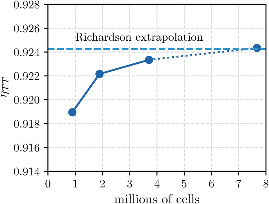
The computational mesh is generated with Ansys-Turbogrid. To reduce the computational cost per simulation, which is critical in shape optimization tasks, periodic boundary conditions are exploited. Therefore, the computational domain includes a single-blade passage containing the main blade, the splitter blade, and the vaneless diffuser. Other components, such as the volute and the sealings, are omitted to reduce the computational cost. The first-layer cell distance is comparable with the roughness to exploit the dedicated wall functions. Starting from a coarse mesh composed of 0.9 million elements and doubling the number of elements each time (with the same mesh topology), a grid convergence analysis is conducted, and the results are illustrated in Figure 2. The grid convergence index is evaluated by taking the first three meshes, yielding a Richardson extrapolated efficiency that differs by less than 0.01% from the value obtained with the finest grid (7.7 million cells). The resulting grid convergence index for the total-to-total efficiency
For the baseline geometry, the CFD simulation returns a
Shape optimization
Shape parameterization
To perform the shape optimization, the baseline geometry has to be parameterized with a finite number of control points, which become the design variables. This task is accomplished by parameterizing the meridional channel and the blade angle distribution with Bezier control points as in Figure 3. Four control points are used to reproduce the meridional hub contour
Figure 3.
Compressor stage parameterization. (left) meridional channel. (middle) blade angle distribution. (right) vaneless diffuser.
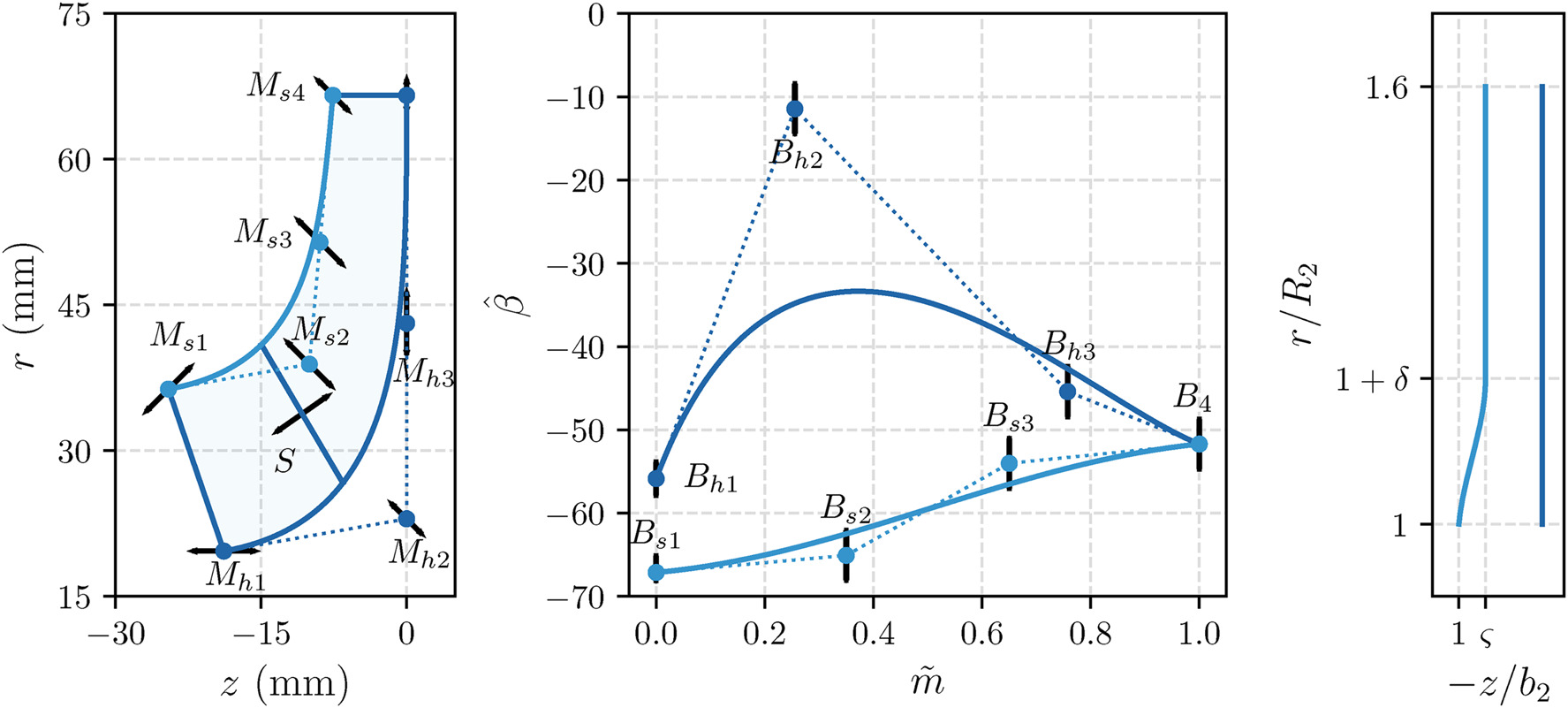
Overall, 17 design variables are considered for the shape optimization problem, of which 7 are related to the meridional channel, 7 control the blade angle distribution, 2 parameterize the vaneless diffuser, and 1 is related to the splitter location. The displacement of each specific control point (horizontal, vertical, or ±45 deg) is indicated in Figure 3. Table 1 reports the design space for each of these design variables.
Table 1.
Design space identified by 17 design variables included in the shape optimization.
Surrogate-assisted evolutionary optimization method
The optimization problem aims to maximize the efficiency, either
The constrained optimization problem is solved with the genetic algorithm (GA). As the GA requires many evaluations to converge, a surrogate strategy is adopted to reduce the computational cost, leveraging the surrogate-assisted strategy implemented in the in-house optimizer FORMA (Persico et al., 2019). At first, 170 stage geometries (ten times the number of design variables) are generated within the prescribed design space with Latin hypercube sampling. The objective function and the constraints are calculated with CFD simulations as detailed in section 2. The mesh is regenerated each time using the grid-convergent set-up described before. Four distinct Kriging, one for each objective function/constraint, are introduced as surrogates of the CFD simulation. The employed Kriging models have up to second-order monomials of the input variables as the mean trend and incorporate a Gaussian correlation function. The Kriging hyperparameters are determined by maximum likelihood optimization. Once the four Kriging predictors are obtained, the GA optimization is executed on surrogate responses. The so-identified optimal stage geometry is assessed with CFD, and new Kriging predictors are re-generated on all simulated cases, namely the initial design of experiments plus the simulated optimal geometries selected by the surrogate optimization. Throughout this acquisition phase, the surrogate reliability progressively increases by adding geometries close to the expected optimal region. The acquisition procedure is repeated for 200 iterations.
A single iteration, which includes surrogate interpolation and optimization, mesh generation, CFD assessment, and post-processing, takes approximately 30 min on a cluster node Dell Intel®Xeon®Gold 6,148 equipped with 40 cores.
Convergence history
The evolution of surrogate estimates for the optimization of
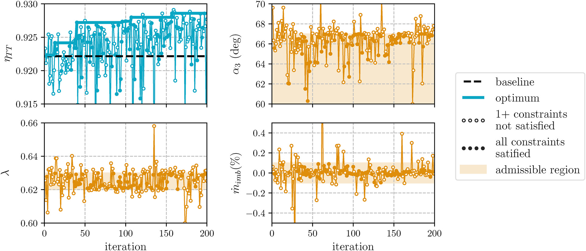
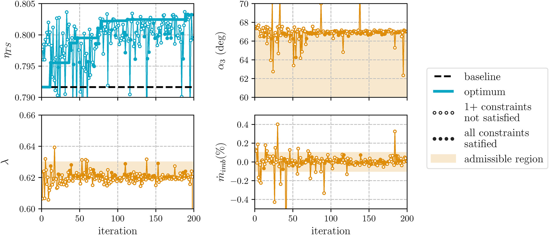
Meeting the targets for
Both optimization tasks successfully deliver a compressor with improved efficiency while satisfying the imposed aerodynamic constraints. The outlet total and static pressures vary within 1% compared to the baseline value. Maximizing
Optimization outcomes
Figure 6 compares the baseline and optimal impeller geometries. On the one hand, starting from the optimization of
Figure 6.
Baseline and optimized impeller geometries. (left) meridional view. (middle) blade angle distribution. (right) blade-to-blade view at hub and tip.
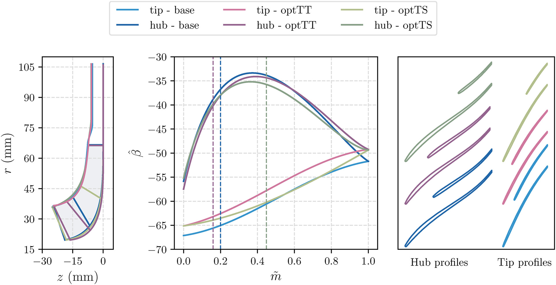
On the other hand, looking at the optimization of
The three-dimensional views of the main and splitter blade for the three cases are displayed in Figure 7. The complete list of optimal design variables is reported in Table 2. From this table, it can also be observed that optTT has a vaneless diffuser with a pinched section that extends up to
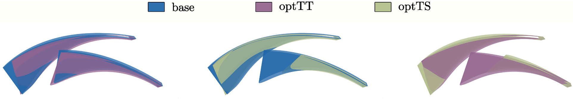
Table 2
Optimal design variables.
To understand the effect of the optimizations, the Mach number fields near the tip region for the three geometries are reported in Figure 8. Two main flow features can be recognized in the baseline field: first, a flow separation originating on the suction side around
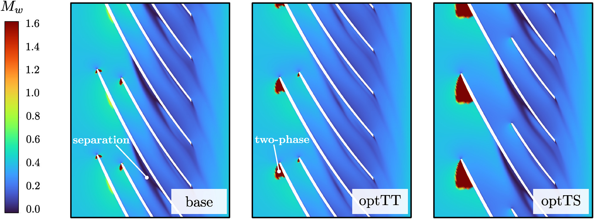
The two-phase region is slightly increased for optTT due to the positive incidence resulting from a more meridional inlet blade angle. However, this leads to a considerable reduction in flow detachment on the blade suction side, motivating the optimization path to enhance the total-to-total efficiency. Interpreting optTS is more complex, as the two-phase region considerably enlarges while the separation remains unaltered. This expansion primarily arises from the reduction in splitter length, which contributes to increased blade loading on the main blade. Interestingly, despite these differences, the total-to-total efficiency of optTS matches that of optTT, resulting in a 0.7 percentage point increase over the baseline value. This observation suggests that the optimization problem utilizing
For a comprehensive compressor performance analysis, it is worthwhile to investigate the variation in the operating range after the optimization. The performance map across the flow range at the nominal rotational speed is depicted in Figure 9. Both the right and left limits are altered due to the optimization. The two optimized cases exhibit a similar operating range, shifting towards larger flow rates compared to the baseline. This implies a reduction in the margin from compressor instabilities and an increase in the margin from choked-flow conditions.
Figure 9.
Total-to-total efficiency (left), total-to-static efficiency (middle), and work coefficient (right) curves over the flow range for baseline and optimized geometries.
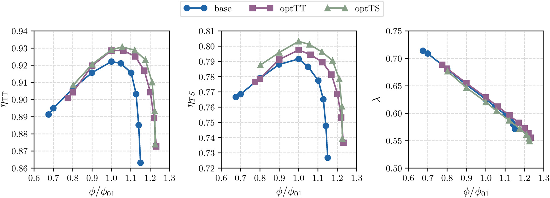
On the one hand, the left limit, representing the minimum mass flow rate without encountering compressor instability, shifts towards a higher flow rate in the optimized cases by almost 10%. One possible explanation is linked to the absolute flow angle becoming more tangential at the impeller outlet, diminishing the margin from flow instabilities in the vaneless diffuser. It’s important to note that identifying the left limit with RANS simulations may be inaccurate, as instabilities are inherently time-dependent phenomena and are also influenced by machine-system interaction. In this analysis, the limit is determined based on numerical considerations, such as when the simulation fails to converge to a steady solution (indicated by oscillations in torque larger than 2%).
On the other hand, the right limit, indicating the maximum mass flow rate before choked-flow conditions occur, increases by 8%. As experimentally demonstrated (Toni et al., 2022), sCO2 compressors are susceptible to premature choking due to the sudden drop in the speed of sound for the two-phase flow mixture. Choked-flow conditions occur similarly between the baseline and optimized geometries, namely when the two-phase region occupies the entire blade channel at the impeller inlet, establishing the sonic throat. The enhanced swallowing capacity of the compressor results from the larger flow passage area at the throat section, attributed to the increase in hub curvature in the case of optTT and to the reduction in splitter length in the case of optTS.
Conclusion
This work discusses the first attempt at shape optimization for an sCO2 centrifugal compressor stage. The baseline stage consists of a single stage that yields an overall pressure ratio of approximately 3, starting from the upstream total conditions
The shape optimization method is applied to enhance the baseline efficiency while constraining the work coefficient and the absolute flow angle at the impeller outlet. Both total-to-total and total-to-static efficiencies are considered as objective functions. In both cases, the optimization converges to a new compressor shape that is more efficient and satisfies the imposed constraints. Optimizing for total-to-static efficiency yields a substantial increase of 1.1 percentage points, along with a 0.7 percentage point increase in total-to-total efficiency. This efficiency enhancement is achieved by reducing skin friction loss in the impeller through the reduction of splitter blade length and improving the vaneless diffuser. Optimizing for total-to-total efficiency results in the same 0.7 percentage point increase in total-to-total efficiency, albeit with a smaller improvement of 0.6 percentage points in total-to-static efficiency. In this scenario, the improvement is achieved by modifying the blade channel to suppress flow separation at the tip, while also enhancing the vaneless diffuser, albeit with a lower pressure recovery coefficient compared to the optimized geometry for total-to-static efficiency.
As a side effect of both optimizations, the operating range of the compressor changes, with a reduction in surge margin and an increase in the choking limit. This finding suggests the potential for future optimizations that encompass both design and off-design operating points in defining the objective function and constraints.
Nomenclature
absolute flow angle
blade angle
diffuser pinch
density
total-to-static efficiency
total-to-total efficiency
dynamic viscosity
work coefficient
flow coefficient
outlet flow coefficient
diffuser height reduction
total pressure loss in the diffuser
blade height
Bezier control point for the shroud blade angle distribution
Bezier control point for the hub blade angle distribution
speed of sound
pressure recovery coefficient
specific enthalpy
eulerian work
Bezier control point for the shroud meridional contour
Bezier control point for the hub meridional contour
peripheral Mach number
normalized meridional coordinate
mass imbalance
pressure
radius
radial coordinate
splitter location (equivalent to
specific entropy
temperature
thickness
axial coordinate
impeller inlet
impeller outlet
diffuser inlet
diffuser outlet
total quantity
computational fluid dynamic
homogeneous equilibrium model
Reynolds-averaged Navier Stoked
supercritical carbon dioxide