
Introduction
Film cooling is an efficient method for cooling gas turbine vanes and blades; a coolant layer covers the surface, protecting it from the hot gas stream coming from the combustor. The coolant also removes some heat via the internal cooling passages of the vane/blade as it makes its way to the surface (Han et al., 2012). Proper cooling design aims to cool the surface using a minimum amount of coolant air, while ensuring a uniform temperature distribution (Sargison, 2001) and limiting the coolant penetration into the mainstream hot gases.
Coolant hole geometry influences the film aerodynamic and thermal behavior. Cooling slots produce more uniform film coverage and superior attachment to convex surfaces than discrete holes (Sargison, 2001). Examples of common slot designs include the tangential slot (Hartnett et al., 1961), the step-down tangential slot (Seban, 1960), and the straight non-tangential slot (Metzger et al., 1968). Compared to discrete cooling holes, the slot geometry has a distinct disadvantage in that it reduces the strength of the turbine components (Logan and Roy, 2003). A compromise between the slot and the circular discrete cooling hole is the racetrack slot which is a rectangular slot with semi-circular lateral edges. For the same coolant area and spanwise spacing, the racetrack slot produces a coolant that has better coverage and consequently higher film effectiveness than a circular coolant hole (Shalash et al., 2013).
Laterally shaping the film cooling nozzles is an effective strategy to reduce the jet lift-off and enhance its lateral spread (Goldstein et al., 1974). An experimental study (Colban and Thole, 2007) showed that the laidback fan-shaped coolant holes reduce the aerodynamic losses and enhance the thermal effect compared to circular holes. A recent optimization study (Park et al., 2019) found that increasing the forward and lateral expansion angles and decreasing the metering length of laidback fan-shaped coolant hole independently increases film effectiveness.
Extending the idea of shaped film cooling holes to slots seems promising; results showed that for the non-tangential slot, shaping the inlet and exit resulted in higher film effectiveness and heat transfer, particularly in the far downstream region (Farmer et al., 1997). Shaping both the slot inlet and exit gives the best film cooling performance as it preserves the turbulence elimination effect at both ends (Hyams et al., 1996). Another variation on the shaped slot is “the converging slot-hole” referred to as the “Console” (Sargison et al., 2001). The Console nozzle attempts to preserve the mechanical strength lost in a typical slot by starting from multiple near circular shapes then converging to a continuous slot. The Console nozzle has similar film cooling effectiveness and heat transfer coefficient to a typical slot, and comparable aerodynamic efficiency of no coolant flow (Sargison et al., 2005). This finding has been attributed to the absence of flow separation inside the Console nozzle (due to accelerated flow) and downstream of nozzle exit.
In an attempt to increase the cooling performance of discrete holes, a numerical study (Kim et al., 2012) investigated various non-conventional hole shapes including a fan, crescent, louver and dumbbell-shaped holes. The dumbbell-shaped holes showed the best laterally averaged film effectiveness for the range of studied blowing ratios. The study suggests that moving the coolant laterally rather than allowing it to concentrate at the center results in better coverage and higher overall effectiveness. The dumbbell-shaped hole starts out cylindrical but as it nears the discharge, it looks like two cylinders that merged. The concept of merged cylinders along the entire length of the coolant nozzle was later investigated (Zhou et al., 2019) for different merge ratios; the best cooling coverage and effectiveness were achieved with the largest merge ratio.
While these novel geometries showed enhancement, they were arrived at through conventional trial-and-error design methods. Less restrictive exploration of the design space is possible through the use of more powerful, gradient-based, discrete adjoint optimization. Discrete adjoint solvers have been used in the design optimization of gas turbine film cooling (Madrane et al., 2020) and internal cooling (He et al., 2019). In both cases, the adjoint solver wraps around a RANS-based model of the flow. RANS models are less accurate in predicting highly separated flows (El-Gabry et al., 2010). They assume isotropic turbulence whereas measurements in the wake of film cooling jet show clear turbulence anisotropy (El-Gabry et al., 2013). Despite these drawbacks, RANS-based models are significantly less computationally intensive than Large-Eddy Simulation (LES) and can more reasonably be integrated into an expansive optimization process that requires multiple simulations as is the case with adjoint optimization.
The numerical adjoint optimization enables irregular shape designs for the coolant nozzle which require advanced manufacturing processes. Additive manufacturing is capable of producing radically different designs from the conventional subtractive manufacturing processes and allows for novel solutions to highly challenging engineering problems (Fu et al., 2018). While some researchers (Snyder and Thole, 2020) have focused on studying the relation between the cooling performance and the surface roughness of additively manufactured cooling holes, others have begun investigating design concepts facilitated by the recent development in additive manufacturing. Internal cooling passages made of wavy channels (Kirsch and Thole, 2017), blood vessel-shaped transpiration cooling holes (Min et al., 2019), and curved film cooling holes that generate Dean vortices (Chen et al., 2020) are a few of the ideas that have taken advantage of the design freedom offered by additive manufacturing.
In this study, a discrete adjoint optimization approach will be used in conjunction with a RANS-based model to maximize the film cooling effectiveness by morphing the coolant nozzle from regular to irregular geometry.
Research methodology
Research strategy
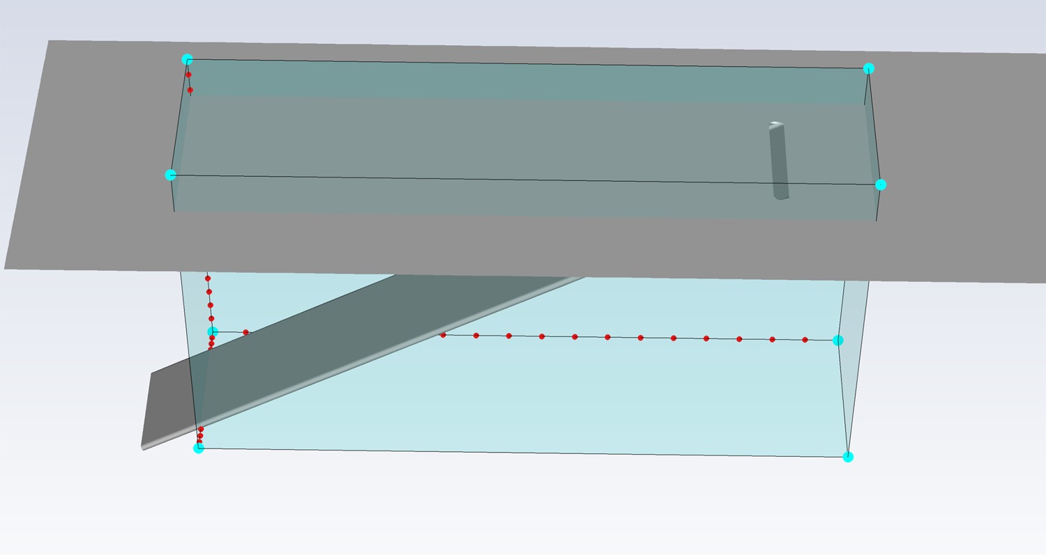
In order to ensure an unbiased comparison between different coolant hole shapes, all other parameters which influence film cooling performance were neutralized. This means applying the same boundary temperatures, velocity ratio, and coolant cross-sectional area for all the cases to guarantee fixed blowing and momentum flux ratios. The ratio of the coolant hole width (w); alternatively, the round hole diameter (D); to the domain pitch (p) was also fixed to eliminate the effect of the coolant hole lateral extent on the laterally and the area averaged results. Figure 1 shows the geometric parameters used throughout this study. Comparisons are made of the adiabatic film effectiveness and Nusselt number on the surface; as well as the temperature, velocity, and vorticity at different normal-to-wall planes.

The first step in the research is validating the CFD model using experimental data. After validating the model, the racetrack slot is compared to the circular coolant hole, demonstrating the superiority of the racetrack slot. Next, the aspect ratio of the racetrack geometry is varied in search of improved performance (Alshehaby et al., 2017); note, the aspect ratio is defined as the ratio of the racetrack straight spanwise length (s) to its streamwise thickness (b), as illustrated in Figure 1. The best racetrack geometry served as a starting point for the irregular shape optimization using the Adjoint solver (Alshehaby and El-Gabry, 2019), an advanced add-on module to ANSYS Fluent software.
Data used for validation
The experiments selected to validate the numerical study include velocity data (El-Gabry et al., 2013) in addition to temperature and heat transfer values (Thurman et al., 2011). The geometry consists of three 19.05 mm (0.75-inch) coolant holes inclined at a 30° with a pitch-to-diameter ratio of 3. The length of each coolant passage is greater than 23D to achieve fully developed coolant flow at the hole exit for both blowing ratios tested: 1 and 2. The tests were implemented in a suction type tunnel. Three sets of experiments were conducted. To measure the velocity, the mainstream and the coolant air were kept at the room temperature and no heat is transferred from, or into, the fluid domain. To obtain the adiabatic film effectiveness, the coolant air was cooled 20°C below the mainstream air temperature and no heat is transferred from, or into, the fluid domain. Lastly, to obtain the heat transfer coefficient in terms of Nusselt number, a constant heat flux was applied using a thin Inconel sheet connected to electrically powered copper bus bars and covering the test surface in the downstream vicinity of the cooling holes exits; the coolant air was cooled 20°C below the mainstream air temperatures. For all three sets of experiments, the mainstream air inlet velocity is kept at 9.1 m/s (30 ft/s). The uncertainties in the mean velocity and velocity fluctuations were less than 4% and 5% respectively. The freestream turbulence intensity at the inlet is about 4% and the integral turbulent length scale is 3 mm. The uncertainty in temperature at the region of interest was less than 5%.
Data presentation
The same Cartesian coordinate orientation used by the experimental studies (Thurman et al., 2011; El-Gabry et al., 2013) is adopted for the current numerical research: the domain is symmetric about the plane [Y = 0], the test surface and hole exit lie on the plane [Z = 0], and the X-coordinate is along with the mainstream flow direction. Only one hole with one pitch (p) lateral extent is modeled for each case in the numerical study taking advantage of periodicity to reduce the computational domain. For the circular hole case, the coordinates’ origin is set at the coolant hole leading-edge; so that the circular coolant hole extends from [X/D = 0] to [X/D = 2] in streamwise direction, and from [Y/D = −0.5] to [Y/D = 0.5] in the spanwise direction; to be consistent with the presentation of the experimental results illustrations. For all other hole shapes, the trailing-edge was kept at [X/D = 2] regardless of the leading-edge position.
Numerical modeling
A non-uniform hexahedral structured grid was generated using ANSYS ICEM CFD 17.1 mesh generator. Figure 2 shows a general view of the computational domain's surface mesh. A denser mesh is used in the region of interest downstream of the coolant exit hole, where high turbulence and rapid changes in fluid properties are expected. An O-grid was used to preserve grid quality and orthogonality when meshing round passages, as shown in Figures 3 and 4 for circular and racetrack holes, respectively. The near wall grid spacing was adjusted to meet Y-plus requirement for each turbulence model. Tables 1 and 2 show the average Y-plus value at the test surface and the total number of grid elements for each studied turbulence model at M = 1 and M = 2, respectively.
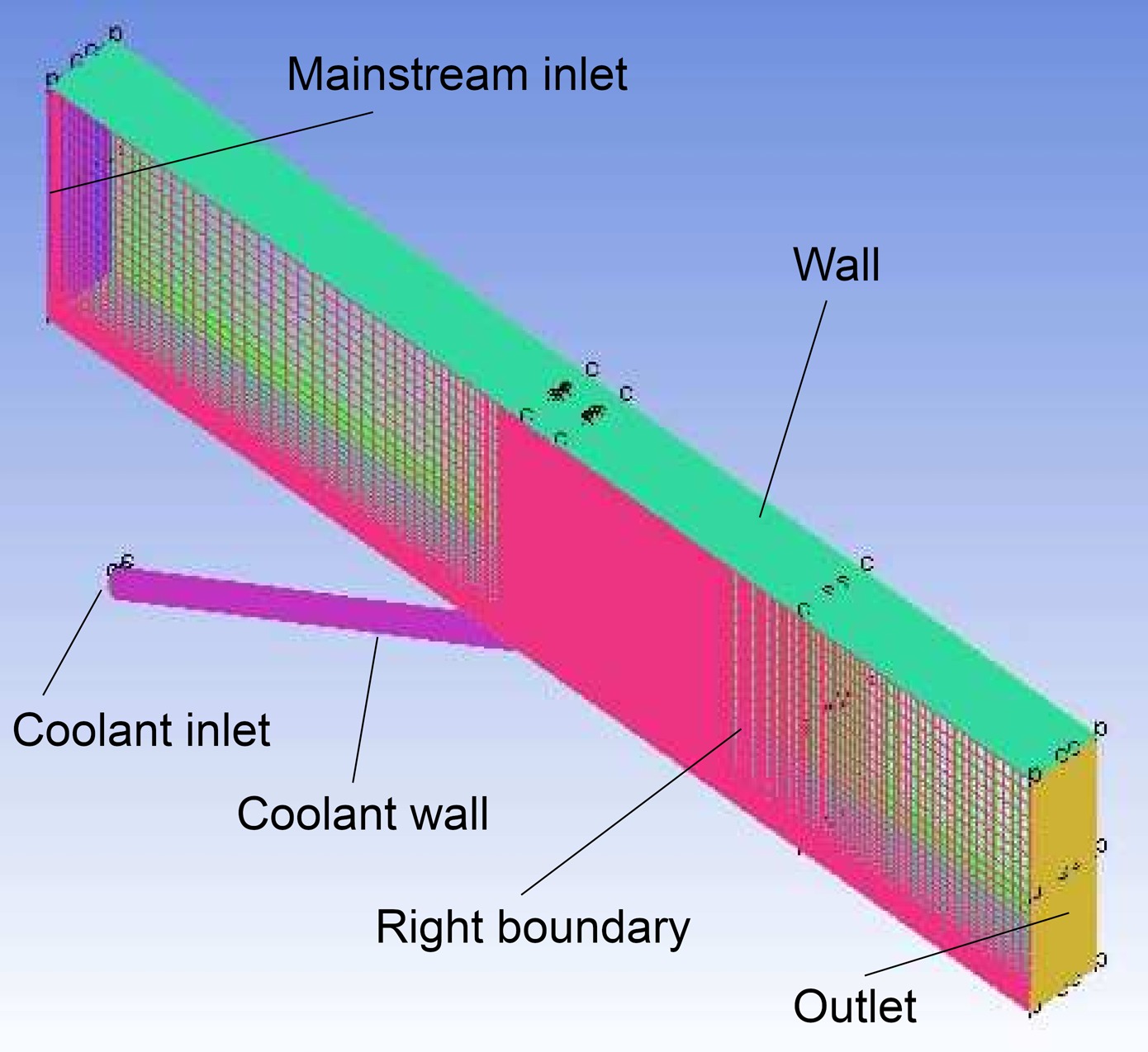
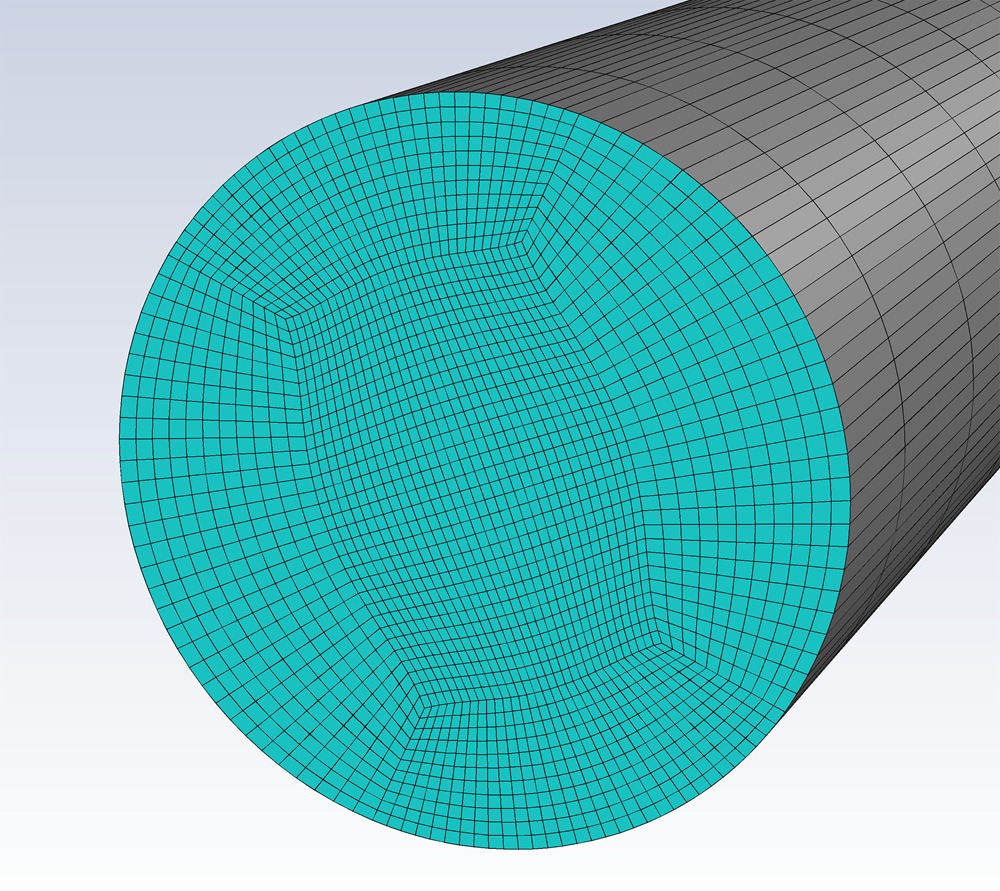
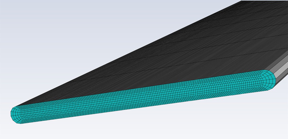
Table 1.
Average Y-plus at the test surface and total number of grid elements for each turbulence model at M = 1.
Table 2.
Average Y-plus at the test surface and total number of grid elements for each turbulence model at M = 2.
| Turbulence Model | Average Y-plus at Test Surface | Total Number of Grid Elements |
|---|---|---|
| Realizable k-ε with scalable wall function | 5 | 1.5 million |
| Realizable k-ε with enhanced wall treatment | 1 | 2.0 million |
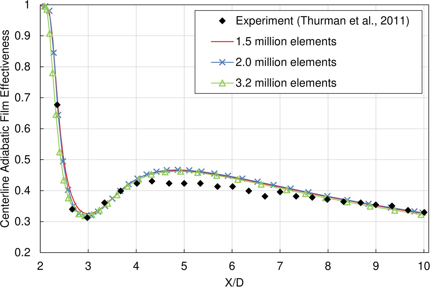
Grid independence was obtained by comparing the centerline adiabatic film effectiveness of consecutive refinements of the grid along all directions. A grid-independent solution is found when no substantial change in the centerline adiabatic film effectiveness is observed with further grid refinement. Figure 5 shows that, for the realizable k-ε model with scalable wall function at blowing ratio M = 1, there is no significant change in centerline adiabatic film effectiveness with successive grid refinements from 1.5, 2.0, to 3.2 million grid elements. Thus, the grid size with 1.5 million elements was used for further analyses. The same exercise was performed to achieve grid independent solutions for all tested models at both blowing ratios, M = 1 and M = 2.
The boundary conditions applied to the CFD model are selected to mimic as closely as possible the experimental conditions; Table 3 lists the boundary conditions for the boundary surfaces shown in Figure 2. The turbulence at the freestream inlet was specified using measured turbulence intensity and length scale. Starting from the coolant hole trailing-edge towards the downstream direction, the “test surface” is defined to simulate the heaters in the experiment; a constant heat flux is applied to the test surface and the remaining walls are adiabatic. Symmetry boundary conditions are used to reduce the computational domain, limiting the lateral extent to one pitch (i.e. one of the three holes was modeled). The fluid is air, modeled as an incompressible ideal gas. Viscous heating is accounted for in the solution of the energy equation.
Table 3.
Boundary conditions of numerical models.
For M = 1, three RANS-based turbulence models were tested and results were compared with experimental data (Thurman et al., 2011): Standard k-ε with scalable wall function, Realizable k-ε with scalable wall function, and EARSM k-ε with scalable wall function. For M = 2, two RANS-based turbulence models were evaluated: Realizable k-ε with scalable wall function, and Realizable k-ε with enhanced wall treatment. The solver used with the Realizable k-ε model is ANSYS Fluent release 16.1, while ANSYS CFX release 16.1 is used for the other models. The SIMPLEC algorithm is used for pressure-velocity coupling. The second order scheme is used for the spatial discretization of the pressure. The QUICK scheme is used for the convective terms: momentum, turbulent kinetic energy, turbulent dissipation rate and energy.
Irregular nozzle geometry optimization using the Adjoint solver
Starting from the optimum racetrack coolant hole shape, the ANSYS Fluent Adjoint solver with discrete adjoint approach was used for the irregular shape optimization. This section describes the procedures followed and the settings applied to the Adjoint solver for the case of M = 1.
Overview of the Adjoint solver
Assuming first order flow sensitivity, the Adjoint solver computes the derivatives of the solution variable with respect to the boundary conditions and geometry. The geometry is parameterized in terms of surface mesh nodes coordinates (ANSYS, Inc., 2015). The solver calculates the required change in a selected input parameter (the shape of appointed geometry parts) to fulfill the objective change in the solution's variable of interest (adiabatic wall temperature) utilizing the sensitivity fields, subject to user-defined geometry modification constraints.
The Adjoint solver has some inaccuracies. It imposes a linear relationship between the changes in the flow variable and changes in the input parameter, making the adjoint solution specific to the current flow state (ANSYS, Inc., 2015). This linearization reduces the accuracy of the solver predictions for nonlinear systems, especially when large change is targeted.
The Adjoint solver assumes steady incompressible single-phase flow in an inertial frame of reference. It can solve either laminar or turbulent flows regimes. These assumptions have no adverse effect on the Adjoint solver predictions in the current study, since they are identical to those used to solve the flow. For turbulent flow, the Adjoint solver employs standard wall functions and assumes frozen turbulence, where the effect of the changes to the state of the turbulence is not considered when computing sensitivities. (ANSYS, Inc., 2015).
The solver is utilized in an iterative approach. The already solved flow domain is used by the Adjoint solver to generate, through mesh morphing, a new geometry that is expected to fulfill the optimization objective. The new generated geometry is then solved utilizing the validated numerical model to evaluate the performance improvement. Depending on the results, the cycle may (or may not) be repeated with the same, greater, or smaller change in the optimization objective.
Solution's observable of interest
Area-weighted average temperature over the test surface, defined by Equation 1, is selected to be the solution's variable of interest. The objective function is to minimize this temperature in order to obtain higher film effectiveness.
Adjoint solver settings
Using the same solution schemes for both the adjoint and the flow solutions gives the most accurate converged adjoint results, while using dissimilar schemes affects, but does not deteriorate, the derivatives calculations (ANSYS, Inc., 2015). The second order and QUICK spatial discretization schemes that were used for the pressure and momentum solutions of the flow, respectively, are not available for the Adjoint solver. Instead, standard and First Order Upwind schemes are used for the adjoint calculations of pressure and momentum, respectively. Solution of the energy equation was enabled during the adjoint calculations in order to calculate the temperature sensitivity field.
In order to mitigate the anticipated solution instability, the dissipation stabilization scheme was employed. Instability is expected due to the complexity of the geometry, the large cell counts, high Reynolds number, and the strong shear at the jet/mainstream interface (ANSYS, Inc., 2015). Further precautions were taken to curb instability growth at the early stage of the calculations by setting the under-relaxation factors for the adjoint momentum, the continuity, the local flow rate, and the energy to 0.6. The values were increased when the solution became stable to accelerate the convergence.
Shape modification constraints
The geometry modification was limited to the mesh nodes contained within the Cartesian box shown in Figure 6. The figure presents the shape modification limits applied to the optimum racetrack slot (the base geometry for the irregular shape optimization approach). Note that the coolant nozzle inlet is excluded, while the exit section was included. Fixing the coolant nozzle inlet guarantees the same blowing ratio for all test cases. Extending the bounding box beyond the coolant nozzle exit allows for free shape modification of the hole exit and avoids severe cell skewness at the interface between the coolant nozzle and the flat plate surface. The movements of the mesh nodes within the Cartesian box follows those of the control points (ANSYS, Inc., 2015). Using 20 control points in each direction of the Cartesian box was found to give smooth mesh transition and was used for all shape optimization steps. Movement of the mesh nodes in test surface normal (Z) direction was disabled to prevent any modification in the flat plate surface topology. The symmetry plane [Y = 0] was defined as a constraint for the mesh morphing process.
Quantifying the objective
Overoptimistic objectives are not practical since they typically cause mesh distortion. Furthermore, the Adjoint solver “linear” prediction may exceed the local optimum point of the selected solution variable (ANSYS, Inc., 2015). Based on practice, an objective of 1% decrease in the average test surface temperature was set for the first and the second irregular shape optimization steps. However, the value was found to be overoptimistic for the third step, since it caused severe mesh distortion. Accordingly, the objective for this step was reduced to 0.5% temperature reduction. The new geometry produced by the third optimization step did not show an actual enhancement in the cooling effect when solved and hence no additional optimization steps were carried out.
Results and discussion
RANS model validation at M = 1
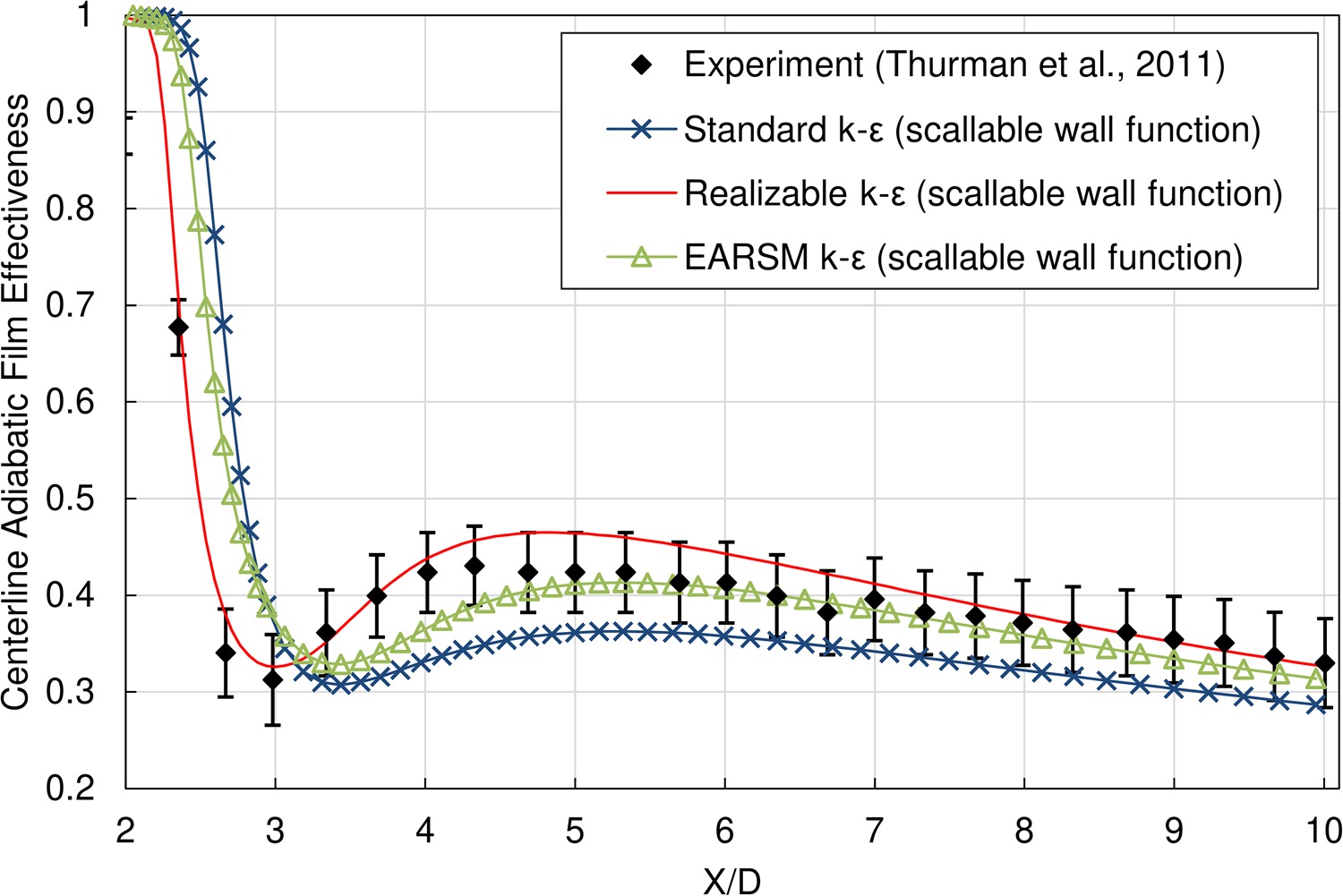
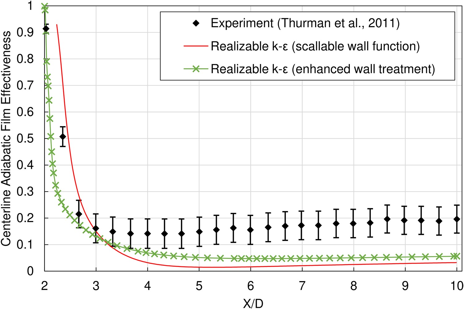
Figure 7 shows the predictions of centerline adiabatic film effectiveness for the three turbulence models evaluated at a blowing ratio of 1, along with the experimental data. The realizable k-ε model with scalable wall function outperforms the standard and EARSM k-ε models with scalable wall functions; all the values predicted by the model lie within the experimental uncertainty. Consequently, the realizable k-ε model with scalable wall function was selected to analyze and compare the performance of different geometries developed.
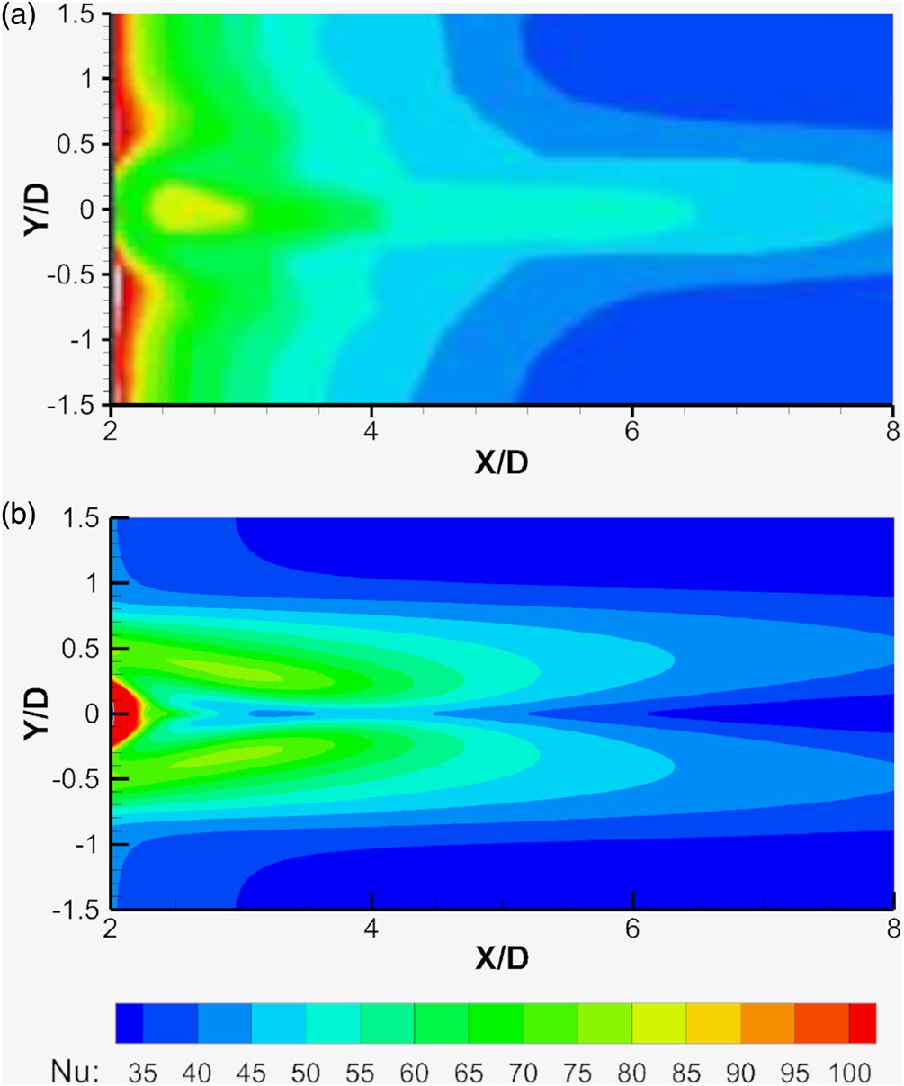
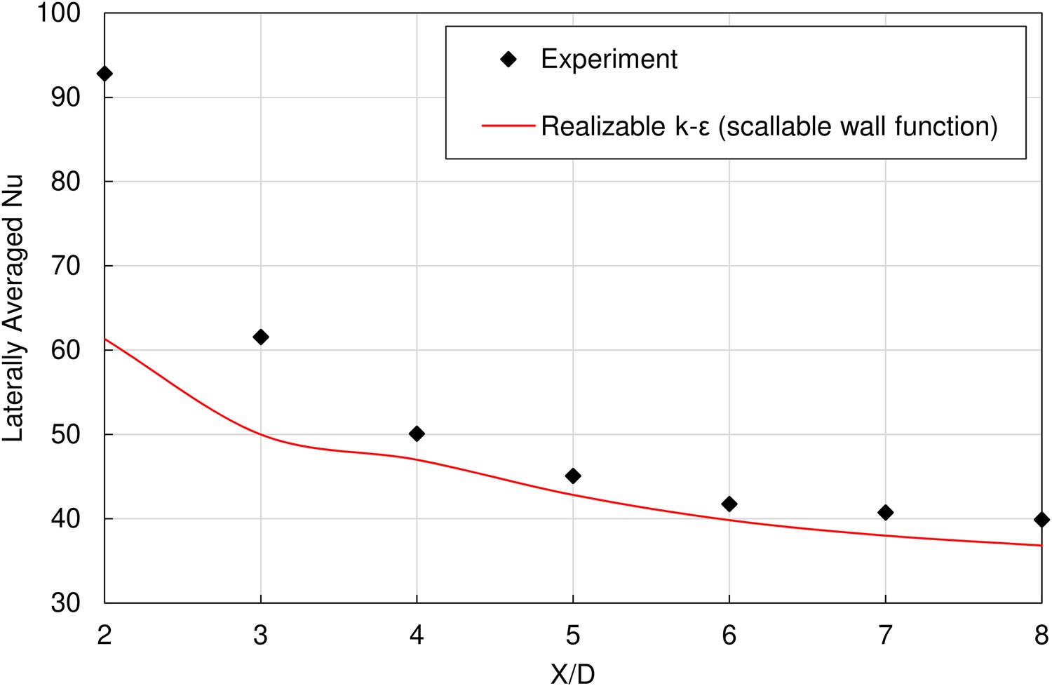
In addition to accurately predicting the centerline film effectiveness, a complete validation details (Alshehaby, 2018) shows that the realizable k-ε model with scalable wall function was also able to predict the velocity and temperature fields. Figure 8 shows a comparison of the Nusselt number contours from the experiment with those predicted by the CFD model for a circular cooling hole. Though the predictions differ at the centerline and locally at the hole exit, they share some similarities particularly in the lateral spread of the coolant and the overall magnitude of the heat transfer. Figure 9 is obtained by laterally averaging Nusselt number over the test surface; it shows that the numerical model predicts the heat transfer coefficient well, except near the coolant hole exit where it underestimates Nusselt number. The figure confirms the ability of the realizable k-ε model with scalable wall function to predict film cooling performance.
Figure 8.
Comparison of Nu contours on the test surface at M = 1 between (a) Experiment (Thurman et al., 2011), and (b) Realizable k-ε model with scalable wall function.
Deficiency of RANS models at M = 2
Figure 10 shows a comparison of two realizable k-ε models: one using scalable wall function and the other using enhanced wall treatment; in predicting experimental centerline adiabatic film effectiveness at a blowing ratio of 2. Both models underpredict the adiabatic film effectiveness, falling rapidly and diverging from the measured values well outside the bounds of the experimental uncertainty. The deficiency of RANS models in predicting film effectiveness at high blowing ratios is commonly noted in the literature, and attributed to the inability of isotropic models to predict the highly anisotropic characteristics of separated flow that occurs at high blowing ratios. Therefore, the current study is limited to the blowing ratio of 1.
Regular shape optimization for the coolant hole
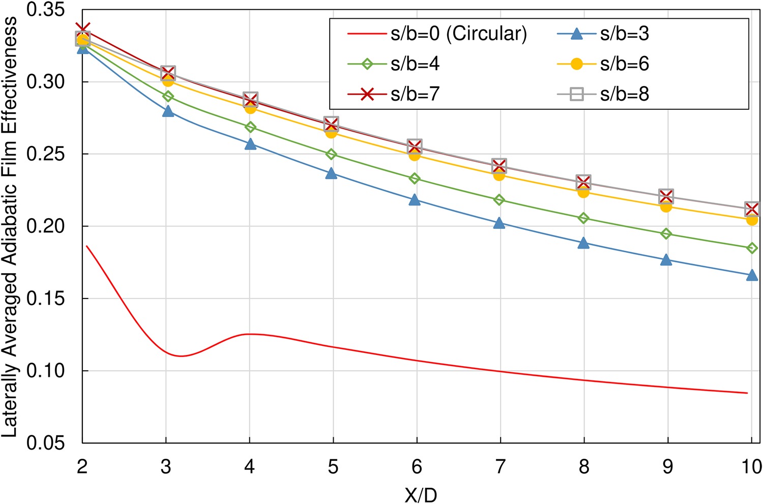
The film cooling performance of racetrack slots having different aspect ratios (ranging from s/b = 3 to s/b = 8) was compared to that of a circular hole having the same flow area and the same pitch-to-hole-width ratio (p/w = 3). The laterally averaged adiabatic film effectiveness curves, presented in Figure 11, show the superiority of the racetrack slot over the circular hole. Increasing the racetrack aspect ratio increases film cooling performance; however, in going from an aspect ratio of 7 to 8, there is a decrease in film effectiveness near the coolant hole exit (X/D = 2–3). At X/D = 10, the laterally averaged adiabatic film effectiveness for the racetrack with an aspect ratio 7 is 0.21; more than the double of that for the circular hole.
Figure 11.
Laterally averaged adiabatic film effectiveness comparison between racetrack slots having different aspect ratios and the circular hole at M = 1.
Researchers use different techniques to achieve reliable results when it is difficult to experimentally mimic real turbine conditions. To capture heat transfer coefficient, heating the test surface with constant heat flux is a frequently utilized approach (Han et al., 2012); either with heated, cooled, or isothermal film injection (Yuen and Martinez-Botas, 2003). Nusselt number contours obtained by the current numerical study were validated against experimental results (Thurman et al., 2011) in which a constant heat flux is applied at the surface with cooled film injection. Accordingly, the higher the heat transfer the better the film cooling. This is not the case in a true engine where reducing heat transfer from the hot gas to the surface is desired.
Figure 12 shows a comparison of Nusselt number distributions over the heated surface for the racetrack aspect ratios 3, 5, and 7. Along the jet centerline, lower aspect ratios produce a sustained jet with high heat transfer maintained further downstream. However, for the overall test surface, larger aspect ratios showed improved heat transfer as a consequence of wider spread of relatively high Nusselt number values. The results of film effectiveness and heat transfer show that the optimum aspect ratio for the racetrack slot is 7.
Figure 12.
Nu contours on the test surface at M = 1 for racetrack slots having (a) s/b = 3, (b) s/b = 5, and (c) s/b = 7.
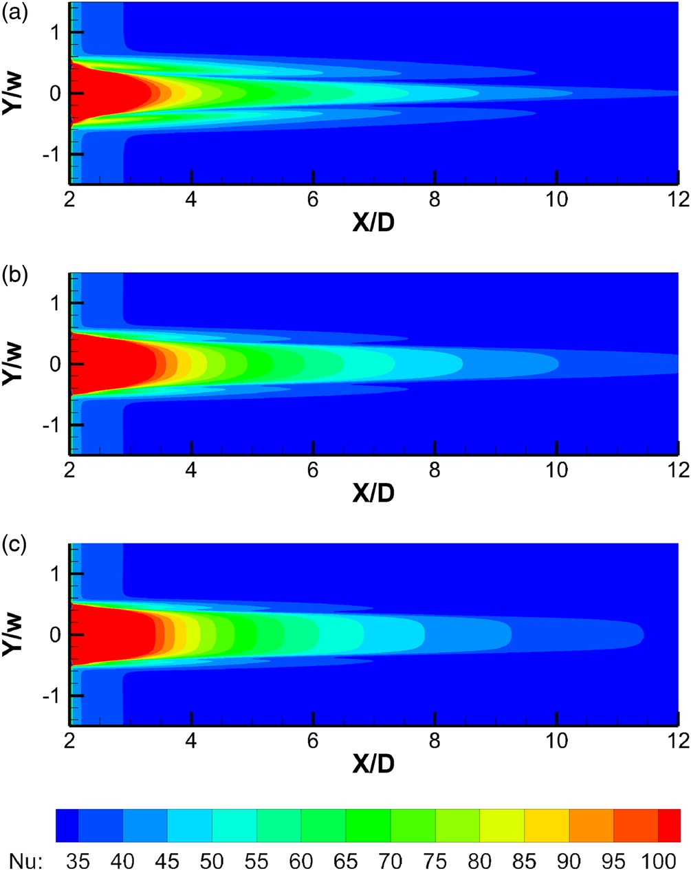
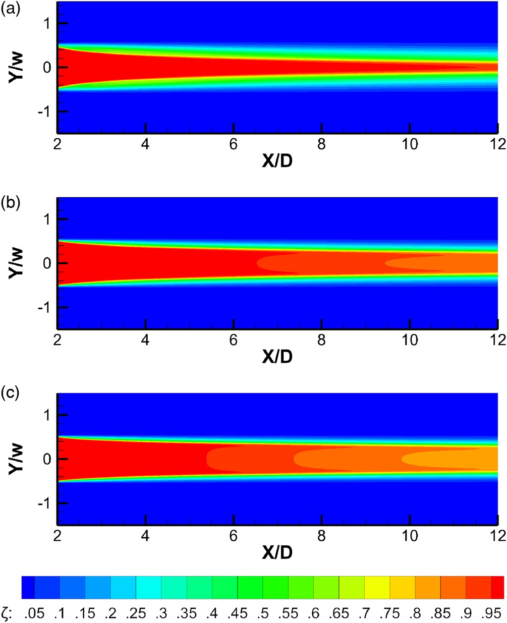
Figure 13 shows the adiabatic film effectiveness contours on the test surface for the racetrack aspect ratios 3, 5, and 7. In spite of a relatively slow decline in film effectiveness along the jet centerline, the contours for the lower aspect ratio shows less uniform effectiveness in the lateral direction. The uniformity is further degraded in the downstream direction, resulting in rapid decline of laterally averaged adiabatic film effectiveness for the lower racetrack aspect ratios observed in Figure 11.
Irregular geometry optimization for the coolant nozzle
Stepwise optimized geometries
In pursuit of even better cooling performance, the coolant hole shape optimization is continued using ANSYS Fluent Adjoint solver which allows for irregular geometry modification. The best performing racetrack (having an aspect ratio of 7) served as a starting point for this irregular shape optimization. The coolant holes exit sections presented in Figure 14 are the outcome of three successive irregular shape optimization steps, with the objective of gradually decreasing the area-weighted average test surface temperature. Note the modification was not limited to the coolant hole exit, and variable coolant nozzle profile was allowed. Figure 15 shows the three coolant nozzle profiles corresponding to the exit sections presented in Figure 14.
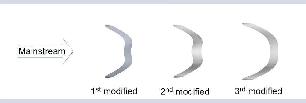
Figure 15.
General view for (a) 1st modified nozzle, (b) 2nd modified nozzle, and (c) 3rd modified nozzle; resulted from three steps of Adjoint solver.

The Adjoint solver calculates the optimal displacement of the surface mesh nodes which satisfies the optimization objective. The optimal displacement is achieved by implementing greater shape modifications to the areas of higher sensitivity. Figure 16 shows the “normal” optimal displacement contours calculated by the Adjoint solver over the surface of the first modified coolant nozzle; positive values indicate a movement towards the flow domain, and negative values indicate a movement away from the flow domain. Applying the resultant of both normal and tangential optimal displacement components on the wall of the first modified coolant nozzle (Figure 15a) resulted in the second modified nozzle (Figure 15b), and is predicted by the Adjoint solver to decrease the average test surface temperature by 1%.
Figure 16.
Example of optimal displacement contours normal to the coolant nozzle wall, predicted by Adjoint solver to fulfill the optimization objective.

A 1% reduction in test surface average temperature was targeted during the first and second irregular shape optimization steps; it was reduced to 0.5% for the third step to avoid mesh distortion. Before stepping forward from each generated geometry, the flow domain was solved with ANSYS Fluent solver using the realizable k-ε model with scalable wall function that proved to yield accurate results as described earlier.
Identifying the optimum geometry
Figure 17 compares the laterally averaged adiabatic film effectiveness for the three irregular nozzles, and the racetrack slot from which the first irregular nozzle was modified. The figure shows an enhancement in the film cooling effect obtained by two successive mesh morphing operations but no improvement was attained by the third mesh morphing. Although the adiabatic film effectiveness of the third modified hole shape started higher than that of the second modified one at the coolant hole trailing-edge, it rapidly declined, becoming less effective than the second modified nozzle by a downstream distance X/D = 3, then less effective than both the first and the second modified ones before reaching the distance X/D = 7. This non-optimized shape modification may be a result of overshooting the local minimum of the solution variable of interest; therefore, an additional trial was made from the second modified geometry, but with a less optimistic objective (0.1% instead of 0.5% reduction in the area-weighted average test surface temperature). The results showed lower laterally averaged film effectiveness than the second modified geometry throughout the test surface. The laterally averaged adiabatic film effectiveness of the second modified coolant hole continues to be higher than those of the racetrack and the first modified holes all the way from the coolant hole trailing-edge until the downstream distance X/D = 10. The maximum advantage in adiabatic film effectiveness, gained by morphing the mesh from the racetrack slot shape to the second modified nozzle geometry (in two successive optimization steps) is 0.12, which sustained from the downstream distance X/D = 3.3 to X/D = 4.4. Afterward, the difference converges, reaching 0.08 at the downstream distance X/D = 10.
Figure 17.
Laterally averaged adiabatic film effectiveness comparison between the racetrack slot having s/b = 7 and the three modified irregular nozzles at M = 1.

The above comparison supports the findings of a recent study (Madrane et al., 2020) that the V-shape cooling holes (which are, to some extent, similar to the third modified hole exit shape) yield better cooling effect than the round hole. The trailing-edge of the second modified hole exit shape (the best performing geometry) resembles that of the dumbbell-shaped (Kim et al., 2012) and the merged cylinders (Zhou et al., 2019) cooling holes; however, the second modified nozzle yields a narrower streamwise hole exit space. Instead of keeping a constant cross section along the coolant nozzle (the merged cylinders) or shaping the coolant hole only near the exit (the dumbbell-shaped hole), the current study added more flexibility by enabling irregular geometry changes across the entire length of the coolant nozzle to obtain the maximum benefit from the adjoint solver.
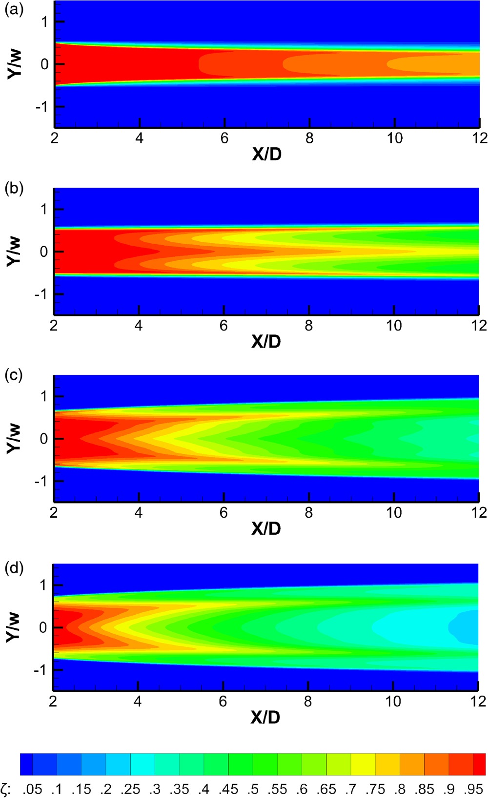
The lateral distribution and the coverage area of the coolant films downstream of the racetrack slot and the three modified irregular nozzle shapes can be understood from their adiabatic effectiveness contours shown in Figure 18. The three irregular hole shapes produce divergent coolant films, while the racetrack slot produces a slightly convergent one. The third modified hole shape (Figure 18d) yields the highest divergence, followed by the second modified one (Figure 18c). The advantage of the film lateral divergence is that it protects the surface, not only by covering more area but also by enhancing its temperature homogeneity. A drawback of increased lateral film divergence is the rapid decline of its effectiveness at the jet centerline.
Figure 18.
Adiabatic film effectiveness contours on the test surface at M = 1 for (a) racetrack slot having s/b = 7, (b) 1st modified nozzle, (c) 2nd modified nozzle, and (d) 3rd modified nozzle.
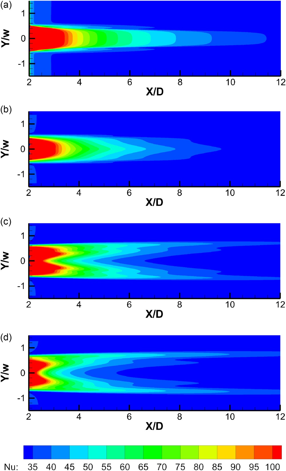
The decline in centerline cooling effect associated with stepping from a coolant hole shape to the next one is also evident in the Nusselt number contours in Figure 19. The presence of two longer spikes of elevated heat transfer in the vicinity of the lateral distances Y/w = ±0.7 for both the second and the third modified nozzles is observed in Figure 19c and d respectively.
Figure 19.
Nu contours on the test surface at M = 1 for (a) racetrack slot having s/b = 7, (b) 1st modified nozzle, (c) 2nd modified nozzle, and (d) 3rd modified nozzle.
Observations of the adiabatic film effectiveness and Nusselt number show that the second modified irregular coolant nozzle geometry (Figure 15b) yields optimum cooling performance among all coolant hole shapes tested throughout this study. Therefore, its aerodynamic and thermal fields will be the focus of further analysis.
Aerothermal analysis
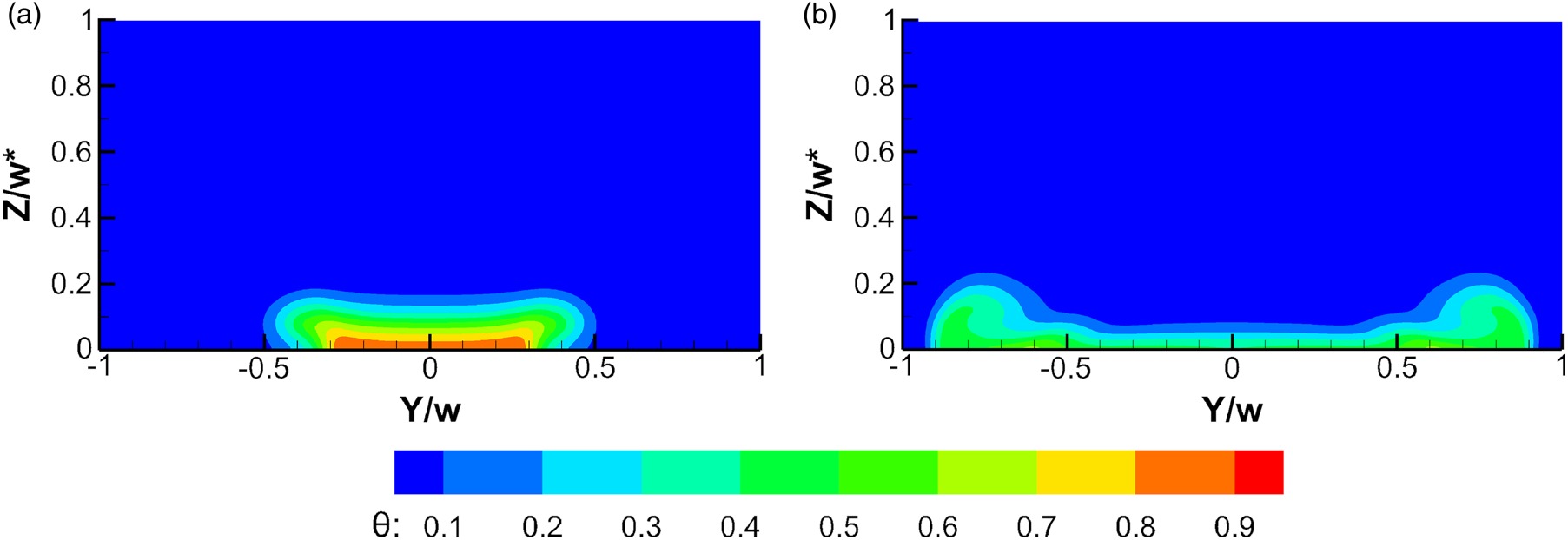
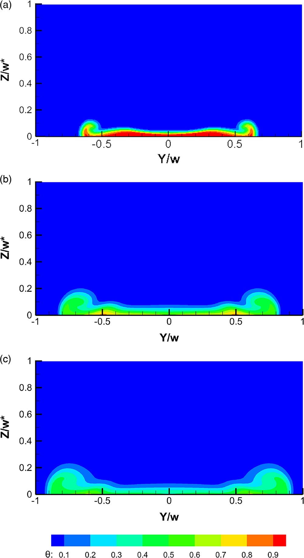
Figure 20 shows the normalized temperature contours on plane X/D = 10 for the best performing racetrack and the second modified nozzle (the best performing geometry). Combining these results with Figure 18a suggests that the thicker film which sustained until the distance X/D = 10 downstream of the racetrack slot (Figure 20a) had kept its core temperature protected from intense thermal dissipation. On the other hand, Figure 20b shows thicker layers of coolant film concentrated on both sides of the domain downstream of the second modified nozzle which explain the elevated adiabatic film effectiveness straddling the centerline observed in Figure 18c.
Figure 20.
Normalized temperature contours on plane X/D = 10 at M = 1 for (a) racetrack slot having s/b = 7, and (b) 2nd modified nozzle.
To show the development of the coolant jet and its attachment to the cooled surface for the best performing racetrack and the second modified (the best performing) irregular geometry, the normalized U-velocity contours along the jet centerline are presented in Figure 21. Both jets do not experience a severe lift-off. However, the irregular shape optimization resulted in a smaller nozzle inclination angle and reduced the jet kinetic energy along the centerline. The lower kinetic energy at the jet centerline of the second modified irregular nozzle indicates that the jet divergence started from inside the coolant nozzle. The smaller inclination angle and the lateral divergence of the jet are attributes of the second modified irregular nozzle as observed in Figure 15b; both attributes have been shown to have a positive effect on film cooling performance (Goldstein et al., 1974; Akbar et al., 2017).
Figure 21.
Normalized U-velocity contours along the jet centerline at M = 1 for (a) racetrack slot having s/b = 7, and (b) 2nd modified nozzle.

One of the most significant aerodynamic features in film cooling is the formation of the Counter Rotating Vortex Pair (CRVP). The size and position of the CRVP influence the jet attachment/detachment and the film cooling effect (Akbar et al., 2017). Eliminating or reducing the strength of the CRVP is desired to mitigate its adverse effect (Hossain, 2020). A structure of CRVP is observed in Figure 22a which shows the cross-flow velocity vectors on the plane X/D = 6 for the optimum racetrack slot. The upward velocity vectors at the jet centerline promote the jet lift-off. The inward tangent-to-wall velocity vectors prevent the film lateral spread and dilute its effectiveness at the sides.
Figure 22.
Cross-flow velocity vectors on plane X/D = 6 at M = 1 for (a) racetrack slot having s/b = 7, and (b) 2nd modified nozzle.
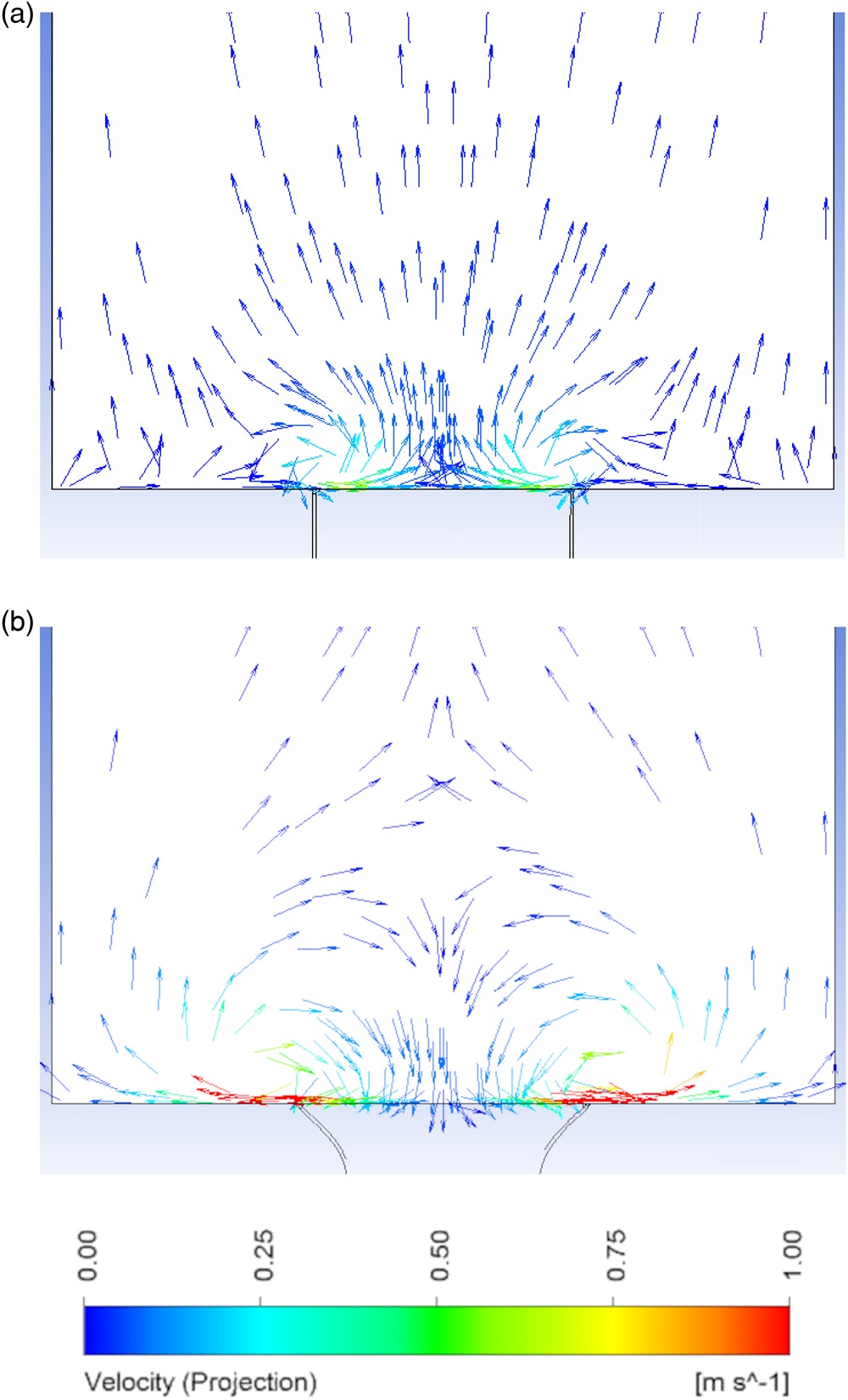
For an incompressible fluid with a uniform density, jet vorticity is produced within the wall boundary layer. Some shaped coolant holes encourage the formation of a vortex pair with a sense of rotation opposite to that of the CRVP; the structure is called an “anti-vortex pair”. The strength and location of the anti-vortex pair can mitigate the jet lift-off effect of the CRVP (Haven et al., 1997). Figure 22b shows the cross-flow velocity vectors on the plane X/D = 6 for the second modified nozzle. The significant findings are the dominance of the anti-vortex pair and the absence of the CRVP. The anti-vortex pair was likely generated due to the geometric attribute of the second modified nozzle exit which resembles shaped holes.
The absence of a strong CRVP improves the cooling performance (Thole et al., 1998). On the other hand, the effect of the anti-vortex pair dynamics on the film thermal behavior of the second modified coolant hole can be understood through inspecting the normalized temperature contours on the planes X/D = 2, X/D = 6, and X/D = 10 shown in Figure 23. The contours confirm the lateral expansion and temperature dilution of the coolant film as it flows downstream. The downward velocity vectors at the jet center region have both unfavorable and favorable effects. The unfavorable effect is diluting the jet core temperature by introducing high temperature air. The favorable effect is promoting the jet attachment to the test surface. Furthermore, the lateral outward velocity vectors near the test surface result in lateral film spread, protecting both sides from the high-temperature mainstream air. Additionally, the upward velocity vectors create thicker film near the domain side-borders.
Conclusions
The realizable k-ε model with scalable wall function accurately predicted the experimental measurements of film cooling aerodynamic and thermal performance at a blowing ratio of 1. For high blowing ratio (M = 2), the model failed to predict the experimental measurements, confirming the recognized shortcoming of RANS models to predict separated flows in detached jets. Accordingly, the optimization study was limited to the flow with blowing ratio of 1.
The realizable k-ε model with scalable wall function predicted the cooling effect for the racetrack slot to be higher than that of the round hole. The racetrack aspect ratio was incrementally increased from 3 to 8 to study its effect on cooling performance. Results showed that the area-weighted average adiabatic film effectiveness over the test surface improved from 0.1 (for the round hole), to 0.21 (for the racetrack slot, having s/b = 3), and reached 0.24 (for the racetrack slot, having s/b = 7). Film effectiveness and Nusselt number results showed that the racetrack slot having the aspect ratio 7 gives the best film cooling performance among the tested regular coolant hole shapes.
In an effort to find even better cooling performance, the research moved from the routine optimization approach restricted to the racetrack geometry towards exploring irregular coolant nozzles geometries utilizing a numerical optimization tool, ANSYS Fluent Adjoint solver. The optimum irregular coolant nozzle geometry was identified in two optimization steps, since no further improvement in the cooling performance was recorded through additional trials. The results showed that the coolant film of the optimum irregular geometry (the second modified nozzle) expands laterally as it moves downstream, covering more surface area. The extended film coverage protects the surface from high-temperature mainstream air, alleviates thermal stresses, increases the area-averaged adiabatic film effectiveness, and improves the cooling performance of the film. A drawback of the wider expansion of the coolant film is the reduced cooling along the jet centerline.
An absence of CRVP and a dominance of anti-vortex pair is observed in the coolant jet downstream of the optimum coolant hole (the second modified). The anti-vortex pair resulted in film lateral expansion. The downward velocity vectors at the jet centerline region improve the jet attachment to the cooled surface, but dilute the jet core temperature. The analysis revealed a great influence of the convective term in film effectiveness dissipation.
Overall, the irregular shape optimization increased the area-weighted average adiabatic film effectiveness over the test surface from 0.24 (for optimum racetrack coolant hole) to 0.34 (for optimum, irregular, coolant nozzle) which is a remarkable enhancement, especially when compared to 0.1; the value for the round coolant hole under the same conditions.
The current study showed promising results by focusing on the film thermal effect; however, it is important to consider the aerodynamic losses for tested coolant nozzles to evaluate their overall impacts on the turbine performance. Running an LES model is also recommended to accurately predict the flow behavior at higher blowing ratio; this would allow for further shape optimization over a wider range of operating conditions.
Nomenclature
A
area
b
racetrack streamwise thickness
D
diameter of film cooling round hole
h
convective heat transfer coefficient;
k
turbulence kinetic energy
M
coolant-to-mainstream mass flux (blowing) ratio
Nu
Nusselt number;
p
pitch; distance from a midway point between two adjacent coolant holes to the next midway point
Pr
Prandtl number
q
heat flux
r
recovery factor;
s
racetrack straight spanwise length (without rounded ends)
T
temperature
Trec
recovery temperature;
Tstatic
freestream static temperature
Ttotal
freestream total temperature
U
U-velocity (velocity in X-direction)
U*
normalized U;
w
coolant hole width; maximum spanwise distance of the hole
w*
width (w) of racetrack coolant slot having s/b = 7
X
streamwise Cartesian coordinate and distance starting from two-round-hole-diameters (1.5 inch) upstream of coolant hole trailing-edge
Y
spanwise Cartesian coordinate and distance from coolant hole centerline
Z
normal-to-wall Cartesian coordinate and distance from flat plate surface
ε
turbulence dissipation rate
ζ
adiabatic film effectiveness;
θ
normalized air temperature;
λ
thermal conductivity