

Introduction
Micro turbojet engines are widely used in civil unmanned aerial vehicles (UAVs) and general aviation, both of which place high demands on performance, reliability, and lifespan. However, micro turbojet engines typically operate under extreme conditions of high temperature, high pressure, and high rotational speed, subjecting the internal structures to complex aerodynamic loads and severe vibration excitation. These extreme working conditions increase the possibility of engine structural failures, which may further pose a threat to engine safety. The blade (including the disk) of the compressor or booster is one of the main sources of structural failures. For example, the blade accounts for approximately 42% of the total engine failures (Meher-Homji, 1995). Therefore, identifying the compressor structural failures is critical for achieving early fault diagnosis and lifespan evaluation.
Vibration analysis is an effective method for recognising and predicting blade-related structural faults in aero-engines, due to the particular fault features present in vibration signals. Many researchers have contributed to exploring fault feature extraction methods from various perspectives, including dynamic modelling and signal processing based on experimental data acquisition. Some researchers have established finite element models of blades to identify crack failures and assess the degree of blade damage by analysing changes in natural frequencies (Loutridis and Douka, 2005; Masoud and Al-Said, 2009). Sinha considered the asymmetric characteristics of the rotor following fan blade fracture and derived the rotor dynamic equations for an asymmetric rotor with deformable blades. The results indicated that nonlinear phenomena appeared in the casing responses (Sinha, 2013). Hong et al. investigated the dynamic response of the aero-engine at blade-off condition and concluded that it exhibits nonlinear behaviour under complex load excitation (Hong et al., 2014). Hong et al. proposed an instantaneous differential equation for the rotor load transfer system after blade fracture, revealing that the sudden impact load caused by blade fracture undergoes significant attenuation during transmission through the stator (Hong et al., 2023). Changes in blade passing frequency (BPF) and its harmonics, along with spectrum analysis can also be used to monitor and determine the blade-off failure (Satyam et al., 1994; Randall and Sawalhi, 2011). Gubran, et al. proposed a method for identifying blade looseness and cracks based on instantaneous angular velocity (Gubran and Sinha, 2014). Blade-off events produce significant mass unbalance, which may lead to rotor-stator rubbing faults. Ma et al. demonstrated through experiments that rotor-stator rubbing can cause resonance between the natural frequencies of the rotor and stator, and simultaneously producing modulation between the working frequency and the casing's natural frequency (Ma et al., 2023, 2024). Cywka et al. experimentally showed that changing from Jet A-1 to E-3 fuel in a micro turbine alters thermal load and induces rubbing, as evidenced by distinct harmonic vibrations in the spectrum (Cywka et al., 2025).
Although numerous studies have investigated vibration characteristics caused by structural failures related to compressor blades, they primarily focus on faults in axial-flow compressor. These studies mostly rely on simplified rotor structures and numerical models. In particular, many investigations only model the rotor system, neglecting the stators and engine casing. Therefore, the real vibration on the engine casing is not fully captured. Additionally, there is very limited vibration data for micro turbojet engines, especially for engines under practical operating conditions. In fact, micro turbojet engines commonly adopt centrifugal impellers as compressors, leading to significant structural differences compared to axial-flow compressors. This can alter the aerodynamic load and structural failure modes significantly. Consequently, the engine may exhibit different vibration behaviours, which are still unknown.
In light of the above knowledge gaps, this paper investigates the vibration characteristics induced by two types of structural faults in the centrifugal impeller of a micro turbojet engine, i.e., disk fracture and locking nut loosening faults. The vibration acceleration data is collected from the engine casing during full-engine ground testing, and the rotational speed is simultaneously measured. Trend analysis, spectral analysis, and order tracking methods are employed to extract the fault features. The insights provided in this study can support structural health monitoring and fault diagnosis of micro turbojet engines.
Methodology
The experiments are conducted using a micro turbojet engine with a single stage centrifugal impeller and a designed thrust of approximately 120 N. The rotor system adopts the 0-2-0 support configuration, which is commonly used for micro aero-engines. The centrifugal impeller and turbines are located at the front and rear-ends of the rotor, respectively. Particularly, the impeller is mounted on the rotor by a locking nut, which is designed to supply axial force acting on the impeller to lock it tightly. It is worth noting that the centrifugal impeller features a semi-open design with seven primary blades. The number of blades generates a vibration frequency known as the blade passing frequency (BPF), which is paramount for the following vibration data analysis. During full-engine ground testing, the micro engine is securely mounted on a test platform using a rigid support structure, with rubber vibration isolation pads installed at the base to minimize environmental interference.
The engine vibration measurement system is illustrated in Figure 1. Due to the high rotational speed, a vibration accelerometer with a wide frequency response range of up to 12,000 Hz is mounted vertically on top of the casing using a bolt. A Hall-effect speed sensor with fast response and a wide measurement range is used to monitor rotational speed, and the acquired speed signal also serves as a reference for subsequent order tracking analysis. The specific sensor parameters are listed in Table 1. Vibration and speed signals are synchronously acquired using a multi-channel data acquisition card with a sampling frequency of 420 kHz. The system is equipped with a constant-current adapter to provide a stable excitation current to the sensors. Additionally, a pre-amplifier module is used to enhance the overall signal-to-noise ratio (SNR). This configuration ensures that the signal quality meets the requirements for the subsequent spectrum and order analysis. The high-frequency vibration testing system comprehensively covers all acceleration, deceleration, and steady state phases within the engine load spectrum, ensuring a continuous and complete data recording.
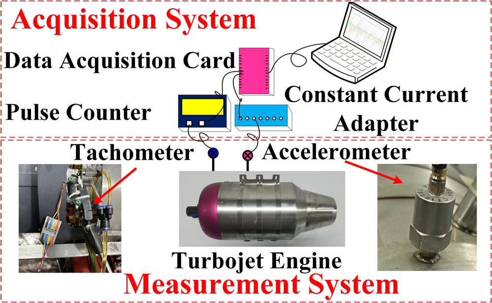
Table 1.
Parameters of the sensors.
| Sensors | Sensitivity | Working range | Frequency response |
|---|---|---|---|
| vibration accelerometer | 20 mV/g | ±250 g | 0–12,000 Hz |
| Hall effect speed sensor | 1.5 mV/V/kA/m | 300,000 r/min | 0–1 MHz |
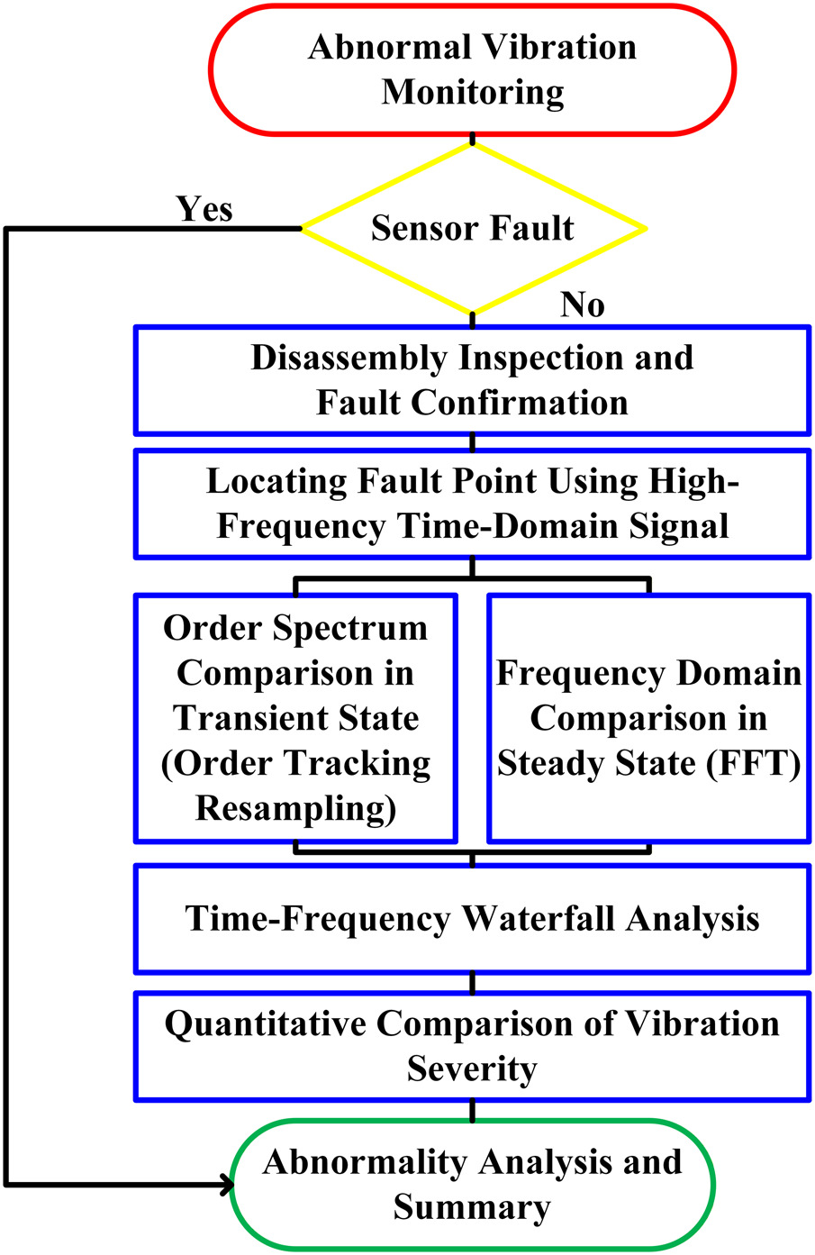
During the engine testing processes, two representative structural failures of the centrifugal impeller are investigated, i.e., disk fracture and locking nut loosening. The vibration data under normal operating conditions is first collected, followed by measurements taken under fault conditions. To comprehensively analyse the impact of centrifugal impeller failures on engine vibration characteristics, this study utilizes a multi-level data analysis procedure. The process includes time domain feature identification, transient state order tracking analysis, steady state frequency domain comparison, fault point time-frequency characteristics, and vibration trend analysis for severity quantification. Prior to vibration analysis, the raw signals were pre-processed using appropriate filtering techniques (e.g., band-pass and notch filters) to effectively attenuate noise and ensure data reliability. The structure of this analysis process is illustrated in Figure 2.
Results and discussion
Centrifugal impeller disk fracture
For the case of centrifugal impeller disk fracture, Figure 3 plots the variation of casing vibration acceleration against time, particularly around the fracture event. In this figure, the left vertical axis represents acceleration, while the right vertical axis is the synchronous rotating speed. These vibration data are collected during the speed rise process from 47,500 to 50,000 r/min, as is illustrated by the solid red line. It can be observed that around 795.98 s, the vibration amplitude suddenly increases, whereas before this time the engine appears in a stable vibration state, peaking at approximately 795.982 s. After the peak, the amplitude decreases but remains higher than it was before 795.98 s. Therefore, at the time of 795.98 s, the increment of vibration indicates the occurrence of engine fault.
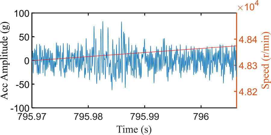
To further reveal the impact of the disk fracture on the engine vibration characteristics, high-frequency vibration signals were analysed using the previously described analysis procedure. Figure 3 presents the time domain vibration acceleration signal during the disk fracture event. Before the disk fracture (795.97 s < t < 795.975 s), the engine was operating under normal acceleration state. Due to the initial imbalance of the system, the vibration amplitude remained relatively low. At t = 795.98 s, the amplitude increased sharply. This phenomenon was initially identified as an excitation response triggered by the disk fracture. After peaking at t = 795.982 s, the amplitude decreased with the change in rotational speed but remained higher than the pre-fracture level.
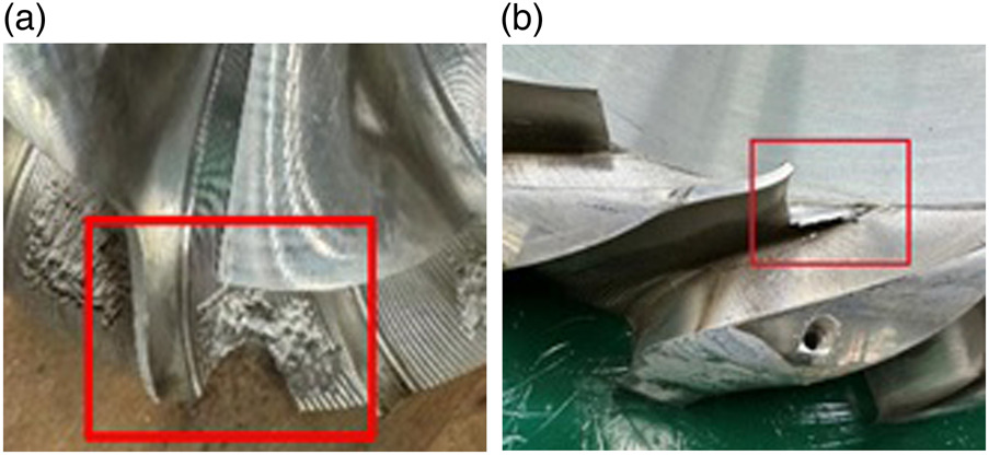
After the test, the engine was disassembled for inspection. It was found that the centrifugal impeller disk had partially fractured, as can be seen in Figure 4a. Furthermore, the radial diffuser blades located after the impeller showed clear rubbing marks and partial fracture, as illustrated in Figure 4b. The structural damage of the diffuser is attributable to the falling part of the impeller disk. Preceding this structural failure, the engine had operated for about 33 h cumulatively. Based on the fault data and the observed component damage, it can be inferred that the failure was caused by structural fatigue, ultimately leading to disk fracture. During prolonged high-speed operation, the centrifugal impeller disk is subjected to significant centrifugal forces and complex aerodynamic forces. These forces continuously act on the disk, causing stress concentration and initiating small cracks at structurally weak points. As the engine speed gradually increases, these cracks propagate further due to cyclic loading. Eventually, the fatigue cracks reach a critical size, leading to disk fracture. The detached fragment is driven by rotational motion and pushed by the flow to move downstream to the diffuser with a remarkably high speed. It then strikes the leading edge of the radial diffuser. The impact results in notches and localized structural damage. It also generates additional vibrational excitation, which further aggravates the dynamic response of the engine.
Figure 4.
Disk fracture and radial diffuser damage. (a) disk fracture and (b) radial diffuser damage.
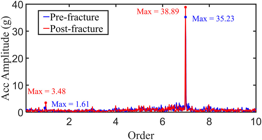
To further identify the vibration characteristics induced by the impeller disk fracture, the order tracking method is utilized to obtain the variation in vibration acceleration before and after the fault occurs. The resulting order spectrums are compared in Figure 5, where the horizontal axis is the order, i.e., the dimensionless vibration frequency normalized by the instantaneous rotational frequency. The solid blue line and the red line represent the acceleration before and after the disk fracture (t = 795.98 s) respectively. Since the centrifugal impeller has seven primary blades, the first 10 order components were compared and analysed. It is evident that before the fracture, the main excitations were the 1st order (RF) and the 7th order (BPF) components. In particular, the vibration at 7X is significantly high. This is a result of the strong aerodynamic excitation force of the BPF acting on the impeller blades. Following the disk fracture, the vibration amplitudes at 1X, 4X and 8X all increased. In contrast, the vibration of the 7X component slightly decreased. These variations indicate that the impeller fracture introduced additional rotor mass imbalance, leading to an increased response at 1X. This result aligns with the findings of (Dang et al., 2021). On the other hand, the aerodynamic force acting on the fractured disk portion was altered, breaking the aerodynamic balance among the seven impeller blades, and resulting in a reduced vibration response at 7X.
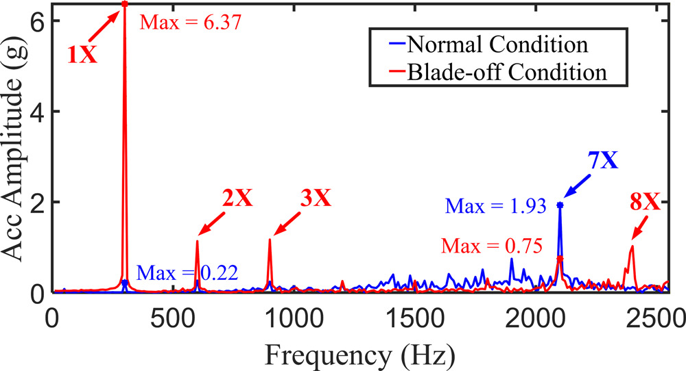
For the steady state, the vibration acceleration spectrums at 18,000 r/min rotational speed are compared in Figure 6 for both normal and fractured conditions, which are respectively denoted by the solid blue and red lines. After the disk fracture, the 1X amplitude increased from 0.24 g under normal conditions to 6.37 g, representing an approximately 28-fold increment. The 7X amplitude decreased from 1.93 to 0.75 g, showing a certain degree of attenuation. The amplitudes of the 2X and 3X harmonic components also increased significantly. This indicates that the fracture disrupted the system's alignment, leading to a rotor system misalignment response. Additionally, modulated frequency components were observed near the 6X and 8X frequencies in the spectrum. These modulations are attributed to the amplitude modulation effect induced by the unbalanced impeller's aerodynamic excitation (Liu, 2024), resulting in modulated sidebands around the BPF. This phenomenon further highlights the significant impact of the disk fault on the aerodynamic and structural coupling characteristics of the system.
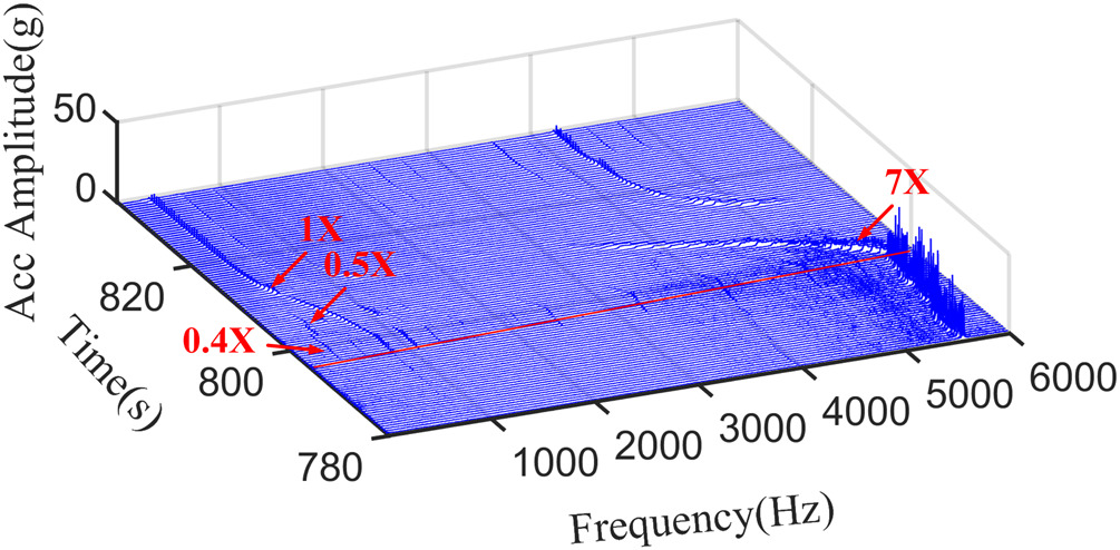
To intuitively observe the dynamic characteristics of frequency components over time, a waterfall plot was generated to illustrate the changes before and after the fault point, as shown in Figure 7. In this figure, the solid red line marks the test time when the disk fracture occurred. It can be seen that before the disk fracture, the response was mainly dominated by the 7X component. At the moment of fracture, the acceleration amplitude at the 1X component increased sharply, while the 7X component decreased to some extent. As the rotational speed gradually decreased, vibrations at subharmonic components (e.g., 0.4X and 0.5X) were temporarily excited. With a further decrease in rotational speed, the 1X amplitude continued to rise, while the 7X amplitude gradually decreased. Meanwhile, the subharmonic components progressively diminished, and the amplitudes of higher-order harmonics declined dramatically. These changes in vibration frequency and the corresponding amplitude reflect the transient-sate characteristics induced by the sudden disk fracture. After approximately 820 s, the vibration response eventually transitioned into a new asymmetric steady state condition.
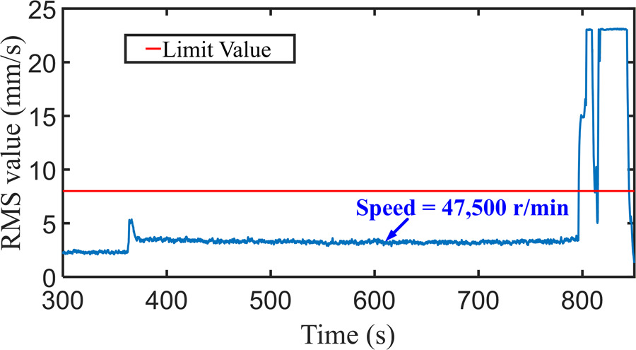
To quantify the impact of disk fracture on the vibration energy of the entire engine, the high-frequency acceleration signals were integrated to obtain the corresponding vibration velocities. The corresponding RMS values at different test times were calculated to reflect vibration severity, as shown in Figure 8, where the solid red horizontal line indicated the velocity limit. The engine operated at 47,500 r/min rotational speed for over 400 s as planned, and the vibration remained stable with an RMS value of about 4.5 mm/s. At 795.98 s (with a corresponding 48,300 r/min rotational speed, as shown in Figure 3), the RMS vibration values increased sharply, exceeding the velocity limit significantly. This is caused by the impeller disk fracture, i.e., the abrupt large amount of mass imbalance.
The detailed RMS values of vibration velocity at different stages are given in Table 2 for both the transient state and the steady state. The former state is taken within a short period just before and after the fault occurs around t = 795.98 s. The steady state corresponds to a stable rotational speed of 18,000 r/min, as illustrated in Figure 7. During the transient stage, vibration severity increased rapidly after the disk fracture. The RMS value reached 321.23% of the pre-fracture level, indicating that the sudden structural failure induces a severe imbalance response in the rotor system, resulting in a transient amplification of the overall engine vibration. For steady state conditions, it is found that the vibration severity of the system after the fracture reached 918.59% of the normal condition. The variation trend of the RMS value is highly consistent with the results from the order spectrum and frequency domain analyses. This consistency further confirms the destructive impact of a disk fracture on the engine.
Table 2.
Vibration velocity RMS value at different stages for fracture test.
| Condition | Transient state RMS value (mm/s) | Steady state RMS value (mm/s) |
|---|---|---|
| Pre-fracture | 5.9759 | 0.2334 |
| Post-fracture | 19.1946 | 2.1440 |
| Relative change | 321.23% | 918.59% |
The engine adopts a 0-2-0 support structure, where both the centrifugal impeller and the turbine can be regarded as cantilever structures. The disk fracture of the centrifugal impeller introduces an unbalanced load at the cantilever end, leading to a deterioration of the system's dynamic balance. Due to the persistent mass imbalance and structural asymmetry caused by the disk fracture, the overall vibration level remains consistently high, far exceeding the engine vibration limit.
Locking nut loosening
Figure 9 shows the time domain vibration acceleration response under the locking nut loosening condition. After the engine startup, the rotational speed gradually increased. At 30 s, the vibration acceleration amplitude exhibited a sudden abnormal increase. This suggests that the locking nut had significantly loosened at that moment, causing unbalanced excitation in the rotor system. The vibration amplitude peaked at approximately 33 s during the startup phase and then slightly decreased. As the rotational speed continued to increase, the vibration amplitude increased again and eventually stabilized at a steady state under the fault condition. This phenomenon indicates that the locking nut loosening fault has a sustained impact on the system vibration, and the extent of loosening directly influences the intensity of the system response.
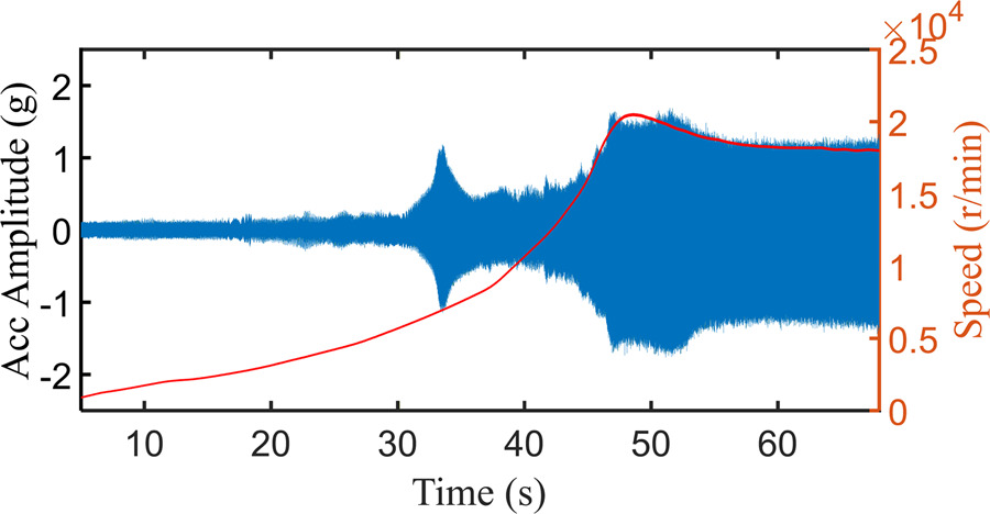
The engine was inspected after ruling out sensor malfunctions, revealing significant loosening of the centrifugal impeller locking nut as shown in Figure 10. The engine had accumulated approximately 60 h of operation and had undergone two overhauls. It is inferred that this failure represents a typical shaft-nut fit failure. Due to frequent engine overhauls and prolonged operation at medium to high rotational speeds, the interference fit between the nut and the shaft gradually loosened, ultimately resulting in the failure of the locking function.
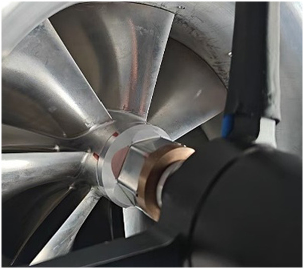
Figure 11 shows the comparison of the order components before and after the occurrence of the locking nut loosening fault. Before the fault occurred, the system exhibited minor 1st, 2nd, and 3rd order responses, mainly due to the initial imbalance and slight misalignment. After the loosening of the locking nut, the amplitudes of the 1st and 3rd orders increased significantly, while the 2nd and 7th order components remained relatively unchanged. This suggests that the loosening of the locking nut changed the rotor assembly alignment, leading to an unbalanced system response and compromising the alignment. The rotor support also became misaligned, introducing additional nonlinear stiffness (Liu et al., 2017). Since this fault primarily originates from structural fit loosening rather than aerodynamic excitation, the 7th order component remained stable.
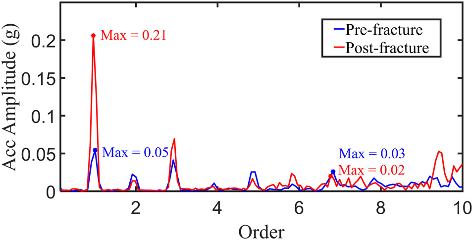
Figure 12 presents the frequency spectrum comparison between the fault condition and the normal condition at 18,000 r/min steady state speed. The results of the frequency domain analysis are consistent with the order spectrum, revealing a significant increase in the amplitudes of the 1X and 3X components, while the 7X component remains relatively unchanged. It is worth noting that although the 7X amplitude did not increase due to the loosening fault, it is still higher than other harmonic components. This indicates that the BPF amplitude is primarily influenced by the aerodynamic excitation caused by the increase in rotational speed, rather than being directly related to the loosening fault.
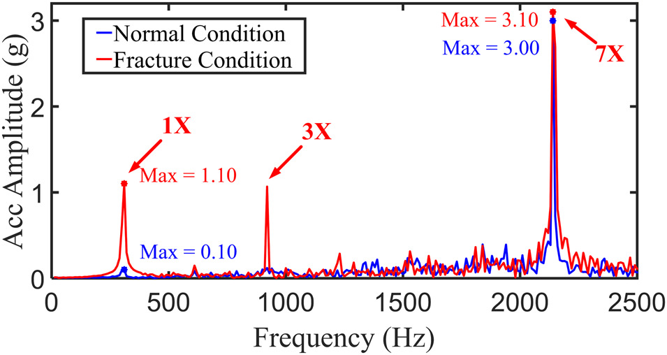
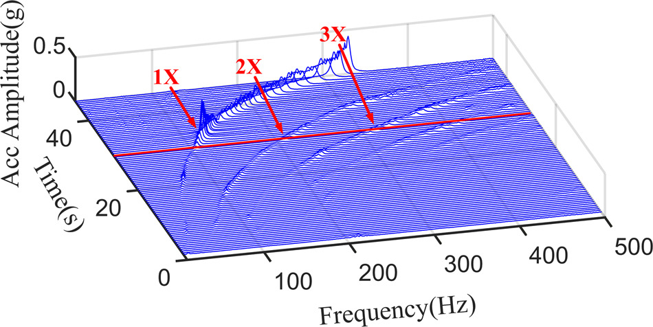
Figure 13 illustrates the waterfall plot of the startup phase under the locking nut loosening fault conditions. Before the occurrence of nut loosening, the amplitudes of the fundamental and lower harmonics were relatively small. At approximately 33 s, the locking nut loosening intensified, causing the 1X amplitude to rise rapidly. As the rotational speed continued to increase, the 3X amplitude exhibited a continuous growth. Eventually, the system stabilized in an unbalanced and misaligned state caused by the loosening fault.
The corresponding RMS values at different test times were calculated to reflect vibration severity, as shown in Figure 14. Following a successful startup, the rotational speed was increased to 18,000 r/min and the values exceeded the limit. The RMS values for different operational stages are summarized in Table 3. The results indicate that during the transient stage, the RMS value after the loosening fault is 1.2 times higher than that of the pre-fault condition, indicating that the loosening of the locking nut exacerbates the unbalanced vibration response. At 18,000 r/min steady state speed, the RMS value under fault conditions is three times higher than that in the normal condition.
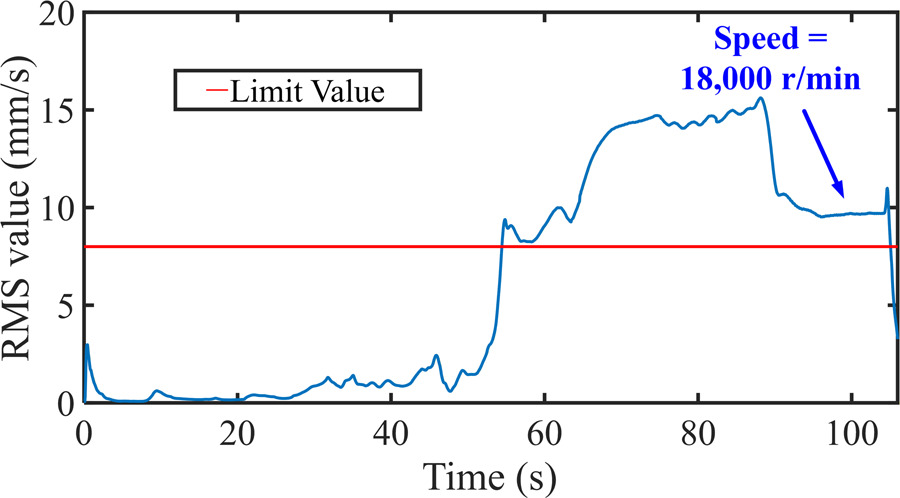
Table 3.
Vibration velocity RMS value at different stages for nut loosening test.
| Condition | Transient state RMS value (mm/s) | Steady state RMS value (mm/s) |
|---|---|---|
| Pre-fracture | 0.1539 | 0.2334 |
| Post-fracture | 0.1838 | 0.6975 |
| Relative change | 119.43% | 298.84% |
This indicates that the fault not only causes a short-term increase in excitation but also leads to the system maintaining a high vibration level over a prolonged period.
Conclusions
This paper systematically analyses the vibration responses associated with two typical faults that occurred during the load test of a micro turbojet engine: centrifugal impeller disk fracture and locking nut loosening. Various analytical methods including order tracking resampling and Fast Fourier Transform (FFT) were used to reveal the dynamic characteristics throughout the failure process. Furthermore, the vibration severity was quantitatively evaluated using the root mean square (RMS) value of vibration velocity:
The disk fracture introduces a significant asymmetric mass imbalance, leading to the emergence of nonlinear responses such as subharmonic drift and frequency modulation during the occurrence of the fracture. In the post-fault steady state phase, the 1X amplitude rises to 28 times that of the normal condition, while the 7X amplitude exhibits some attenuation. The vibration impact of the fault on the entire engine during the transient state and steady state phases reach 321.23 and 918.59% of the normal condition, respectively, exhibiting both sudden and persistent characteristics.
The locking nut loosening fault primarily alters the axial fitting condition, leading to changes in the structural stiffness matrix. This triggers an increase in the 1X and 3X components, while the aerodynamic excitation remains relatively unchanged, resulting in an insignificant variation in the 7X amplitude. The impact of the fault on the engine vibration during the transient state and steady state phases is approximately 119.43 and 298.84% of the normal condition. The loosening fault has a persistent effect on the system vibrations, with the degree of loosening directly determining the system response intensity.