
Introduction
Micro Gas Turbines (MGTs) for co-, tri- or polygeneration are becoming progressively more widespread because of their reliability, flexibility, compactness and very low NOx emissions (Sun et al., 2012). Despite the on-going energy transition and the short-term impact due to the lingering COVID-19 pandemic, the global production of MGTs (especially in Europe) shows a promising increasing trend for the next decade (Palmer, 2021). Although the electrical efficiency is generally lower than the one for similar size internal combustion engines (Ofualagba, 2012), the high total efficiency of MGTs, which can reach 80% thanks to the extraction of the high exhaust gases thermal content through a recuperator (Beith, 2011) is one of the main reason for their increasing adoption. Moreover, exhaust heat can be further extracted by means of a heat exchanger for the production of hot water.
However, if on one side recuperation is beneficial for the overall system efficiency, on the other side it reduces the ability to cool down the hot mechanical components, such as the combustion chamber, being the inlet air largely warmer than what it would be without recuperation. In MGTs, the air entering the combustion chamber is often above 650°C (Enagi et al., 2017). The lower cooling capability, in addition to the higher flame temperature due to warmer inlet gases, causes very high temperatures in the metal components of the combustion chamber, with peaks of 1,200 K in some cases (Cirigliano et al., 2020). Frequent starts and stops induce mechanical stresses at the boundary between materials due to their different thermal expansion, which, if taking place too fast, may cause local permanent plastic deformations. Moreover, long exposure at high temperatures in combustion chambers can promote creep, which can induce thermal fatigue and potential failure of these components. The accumulation of damage in combustion chambers can hence be divided into two categories: the plasticity taking place during transient states (maneuvers, starts and stops) and the viscoplastic-based damage (creep damage) at steady state operation.
It is then necessary to take into account the material degradation due to the progressively increasing viscoplastic deformation; this can be done by adding a scalar parameter to the mechanical model. Commercial Finite Element Methods (FEM) codes, like ANSYS, allow the user to write their custom mechanical model. In this work, the development of a Fortran-based subroutine integrated into ANSYS APDL is presented. On so doing, creep, damage, and material degradation can be modeled. In this work, Lemaitre-Chaboche creep damage model is adopted (Lemaitre and Chaboche, 1978). Secondary creep and isotropic hardening are modeled for the high-temperature resistant alloy Inconel 718. The material degradation is considered by coupling the Young’s modulus with the introduced damage.
The novelty of this paper consists in the determination of Norton coefficients for Inconel 718, which instead of being assumed constant, are temperature dependent and based on experimental data. It is shown that the creep model and subroutine based on these new coefficients correctly reproduces creep, stress relaxation and damage under typical MGT operating temperatures. This model constitutes the foundation of a life-assessment analysis for combustion chambers under creep damage.
Numerical methods
Creep modelling
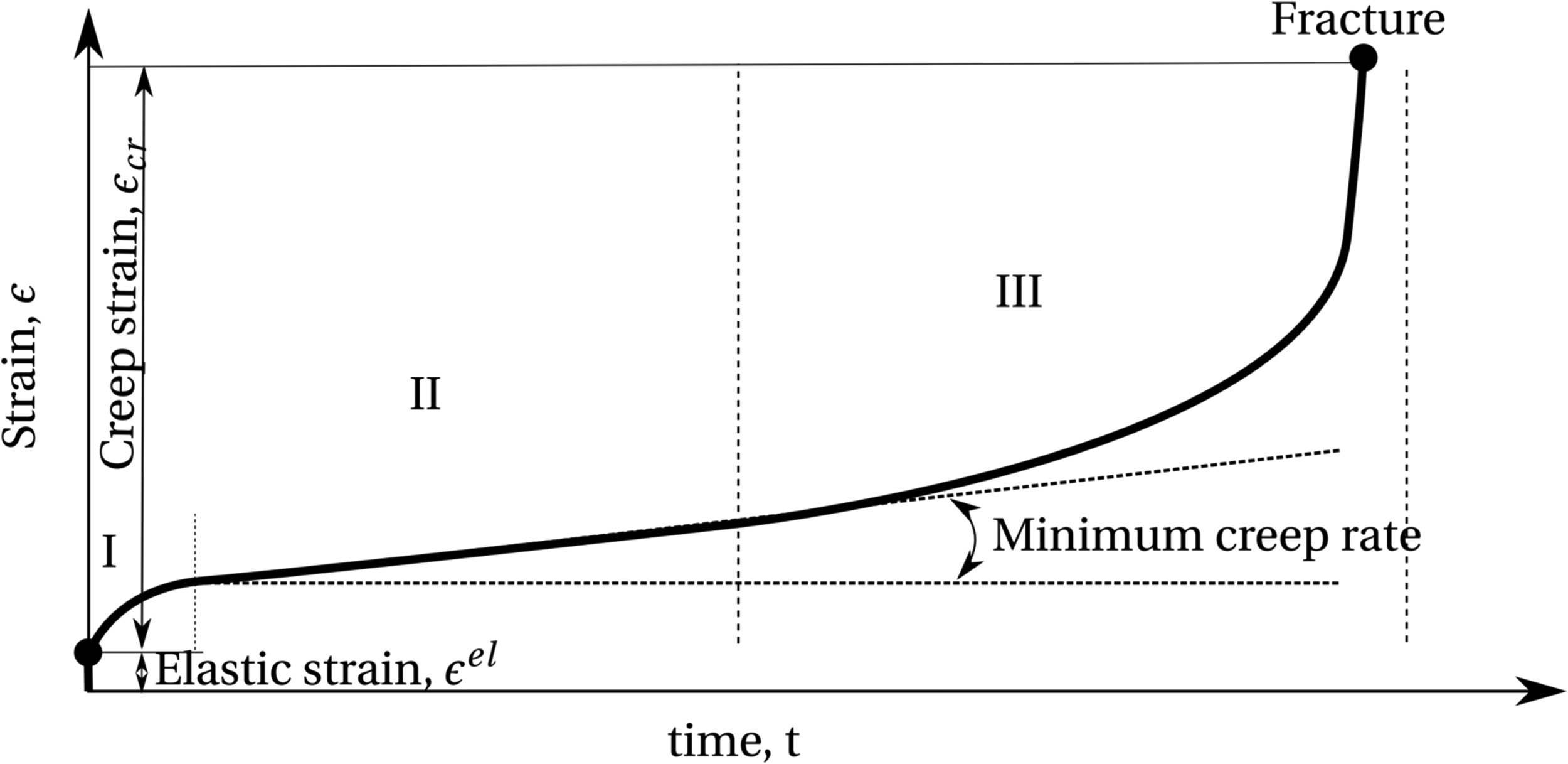
Creep is described as a time-dependent deformation of a material subjected to high temperature and loads below its yield strength for an extended period of time. Temperature, stress, time and material properties influence the rate of creep deformation. The creep phenomena is mainly divided into three stages; i.e., primary I, secondary II, and tertiary III. The three stages correspond to strain rates that are decreasing, constant, and increasing, respectively. Figure 1 depicts a typical creep strain versus time curve. The stage I in the curve indicates the primary creep where the creep strain rate decreases to a minimum value, due the fact that the material is experiencing an increase in creep resistance, attributed to a reduction in the density of free dislocations. The stage II is known as steady-state creep or secondary creep. This regime is also termed as a state of balance between the rate of dislocation generation and rate of recovery, where the former contributes to hardening and the latter to softening of the test material (Abe, 2014). In the tertiary creep stage, the creep rate increases rapidly until failure. This stage describes a softening stage, where the cracks are formed and propagate along the grain boundaries (Betten, 2008). In addition, the microscopic voids accumulate within the material, resulting in a decrease in the effective cross-sectional area (i.e., Necking), which raises the effective stress.
In order to capture the damage caused by creep, the modified Lemaitre-Chaboche model (Chaboche and Rousselier, 1983; Lemaitre, 1985) is used in this study. The effective stress concept Lemaitre and Chaboche (1978) defines the creep damage
where
Equivalent Von-Mises stress and equivalent strain are defined in terms of their stress and strain components:
The total equivalent strain
Creep mechanisms can generally be grouped into two categories: diffusion creep and dislocation creep. Diffusion creep is dominant at lower stresses, and is caused by the movement of vacancies; dislocation creep is present at higher stresses and is caused by the movement of dislocations through the lattice. When a dislocation encounters an obstacle (for example another defect), the former can either climb it (at mid stresses) or glide through it (at high stresses). The creep mechanisms acting in a material can be identified for a range of stresses and temperatures in a deformation map, according to the methods described by Frost and Ashby (1982). A deformation map of Inconel 718 is not available to the authors, but similar Nickel-based superalloys, such as IN738LC Carey et al. (1990) or MAR-M-200 Cieśla et al. (2016), show the onset of dislocation creep at half of the melting point (about
The derivative of creep equivalent strain in time (primary and tertiary creep) can be described in the form of its dependency on equivalent stress, temperature and either creep strain or time, by means of a power law:
where T is the temperature and t is the time. For secondary creep, however, the strain rate is constant, hence, C3 = 0:
where
Table 1.
Norton coefficients for Inconel 718 according to (Liu et al., 2015).
| C1 | C2 | C4 |
|---|---|---|
| 2.147·10−7 | 10.171 | 50,825.89 |
The creep damage evolution is given by:
where
where
Table 2.
Material constants for damage evolution equation.
| a0 | a1 | a2 | r | Z | A |
|---|---|---|---|---|---|
| 13.2478 | 0.7865·10−4 | 0.1924·10−3 | 13.19 | 733.25 | 1,209 |
The scalar creep damage variable
where E is the effective elastic modulus and
By remembering the constitutive relation between
Equation 12, together with Equations 7 and 8, constitute a system of nonlinear differential equations in
Material parameters identification
In applying the Norton formulation (Equation 7) to the analysis of structures one should bear in mind that the material parameters
Since the secondary creep stage is characterized by a constant creep strain rate, one can assume
where T,
with A = 0,442 and
where A and
Table 3.
B and α
| B | |||
|---|---|---|---|
| <11,000 | ≥593 | 2.142 | 1.151 |
| <11,000 | ≤593 | 34.182 | 1.443 |
| ≥11,000 | Any | 2.142 | 1.151 |
In this way, the determination of temperature-dependent parameters
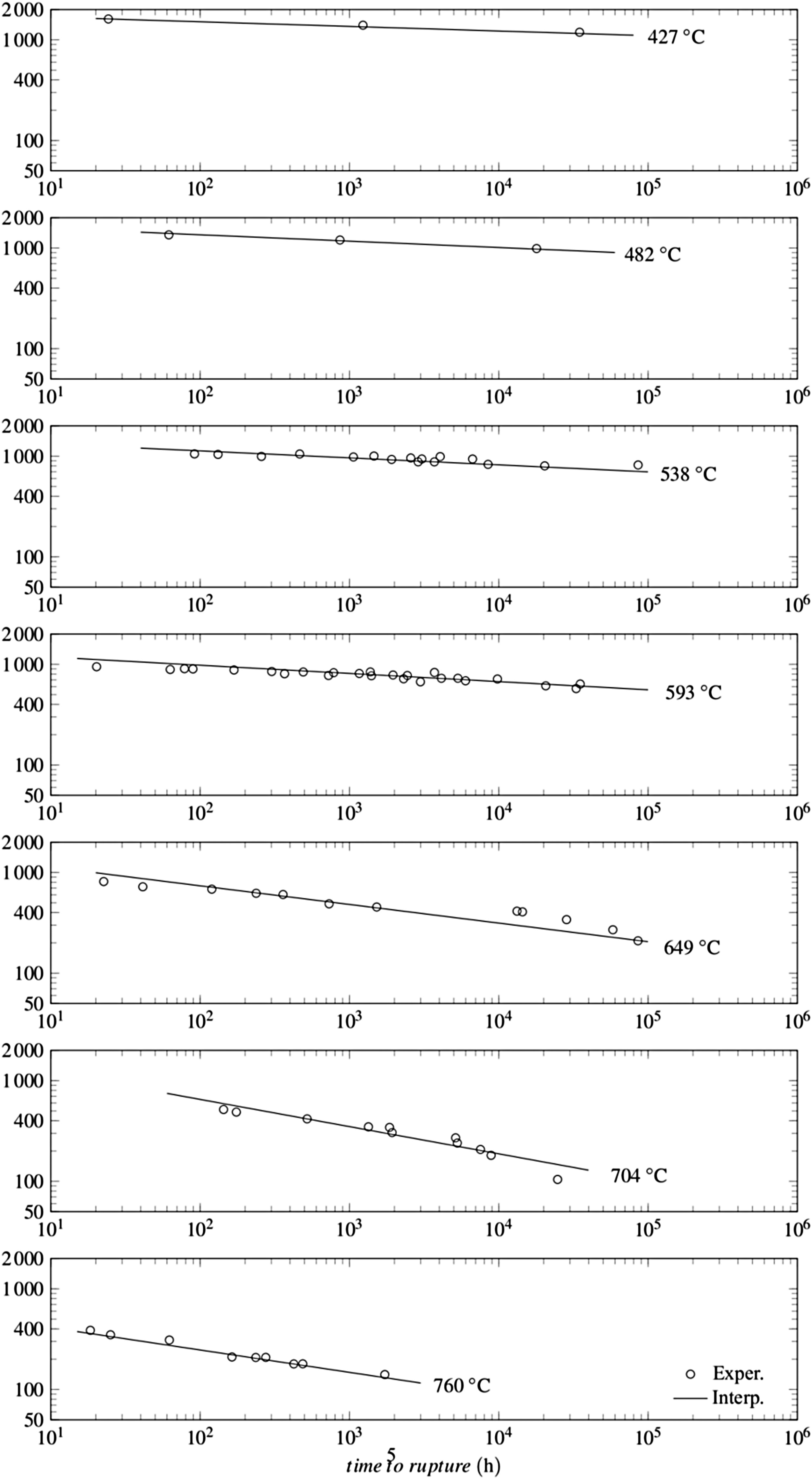
Obtain from creep tests points
compute
compute
substitute
for every temperature T, find the values {
Table 4.
Norton equation coefficients at different temperatures for Inconel 718.
| T (°C) | C1 | C2 | C4 |
|---|---|---|---|
| 427 | 1.10·10−9 | 21.8 | 109,000 |
| 482 | 3.00·10−9 | 15.8 | 84,000 |
| 538 | 4.00·10−9 | 14.4 | 81,000 |
| 593 | 2.00·10−9 | 12.3 | 71,000 |
| 649 | 1.00·10−7 | 5.4 | 34,500 |
| 704 | 5.00·10−6 | 3.7 | 29,000 |
| 760 | 2.00·10−7 | 4.5 | 28,000 |
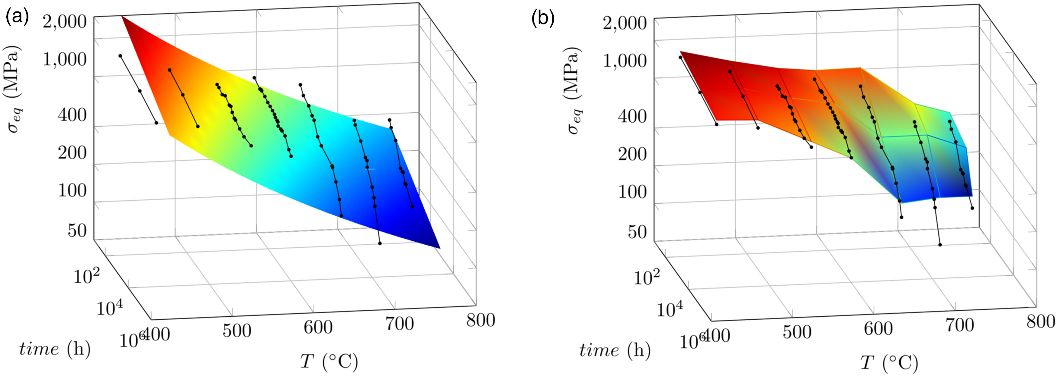
Figure 3.
Creep-tests can be plotted in a three-dimensional space, where each point is represents a test conducted at a specific σ e q t r
User programmable feature USERMAT in ANSYS
In this section, the implementation of a damage-based material model in the commercial software ANSYS APDL is outlined. User Programmable Features (UPFs) are a highly effective and flexible tool to tailor the behavior of the APDL program to suit individual requirements. This is performed by writing a custom subroutine in the C, C++, or Fortran programming languages. One of such subroutines is USERMAT, which is particularly used to define non-linear stress-strain relationships of elastic-plastic materials, custom damage evolution and creep laws, like in this study.
USERMAT subroutine is called at every iteration and executed on each element of the computational grid. The input parameters, such as loads and temperature, are defined by the user during the modelling step. Current stresses, strains and strain increments are the inputs at the start of the timestep. At each iteration, a new elastic, plastic, thermal and creep strain, an effective Young’s modulus and damage evolution are computed based on the constitutive equations and material model described in the previous sections. USERMAT then updates the stresses and the material Jacobian matrix and these values are sent back to the main Finite Element code as outputs (Lin, 1999). The status of every element is checked at every time increment using a strength lifetime failure criterion: when the maximum damage of the structure reaches a threshold value, the subroutine is stopped and the present time is recorded as the lifetime of the component. In this analysis,
The geometry chosen is a rectangular bar of Inconel 718 alloy with a base of 10 × 10 mm and a length of 100 mm. The bar is discretized with 2 hexahedral elements for each short side and with 20 along the length (80 elements in total). Since the application of the present work is three-dimensional and plain strain, SOLID186 elements (20 nodes each, second-order shape functions) are used. The bar is fixed at one end and a displacement is applied to the opposite end to obtain the uni-axial stress state. Material properties of Inconel 718 such as density, thermal expansion coefficients and Young’s modulus (of undamaged material) are taken from data sheets (VDM Metals, 2020).
Results and discussion
The application of the described UPF using the temperature-dependent coefficients is presented in this section. Temperature is set to 750 K. The comparison between the experimental tests, the Norton-Damage model with constant parameters of (Liu et al., 2015) and the Norton-Damage model of this analysis is depicted in Figure 4.
Figure 4.
Comparison between experimental data, the use of the constant parameters from (Liu et al., 2015) and the new, temperature-dependent parameters, at 750 K and initial σ
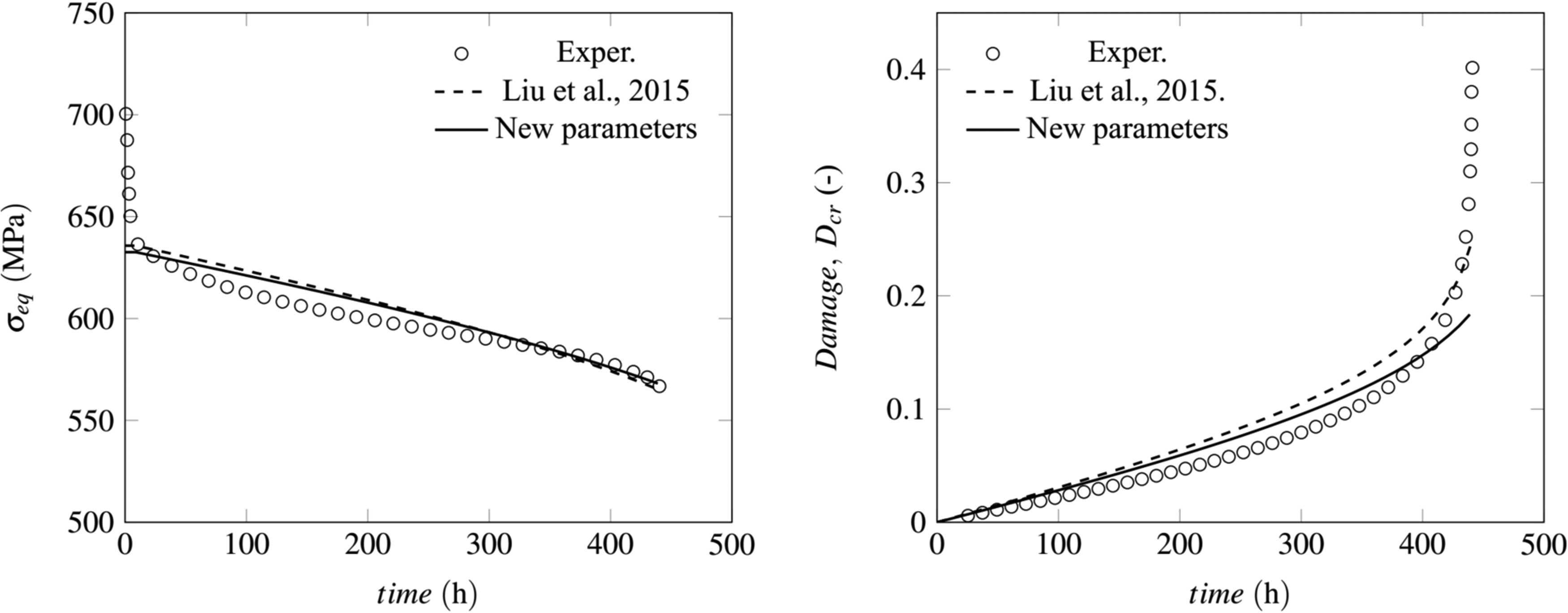
In the experiments, a displacement is applied to one end in order to generate an initial stress of 700 MPa; shortly after, the stress relaxes to a much lower value, around 635 MPa, showing the typical primary creep phase. Afterwards, the stress stabilizes and slowly decreases, due to further stress relaxation. Finally, a rapid decrease in the cross-sectional area of the probe brings the material to failure.
For the two simulations, since the Norton equation only models the secondary creep, an initial
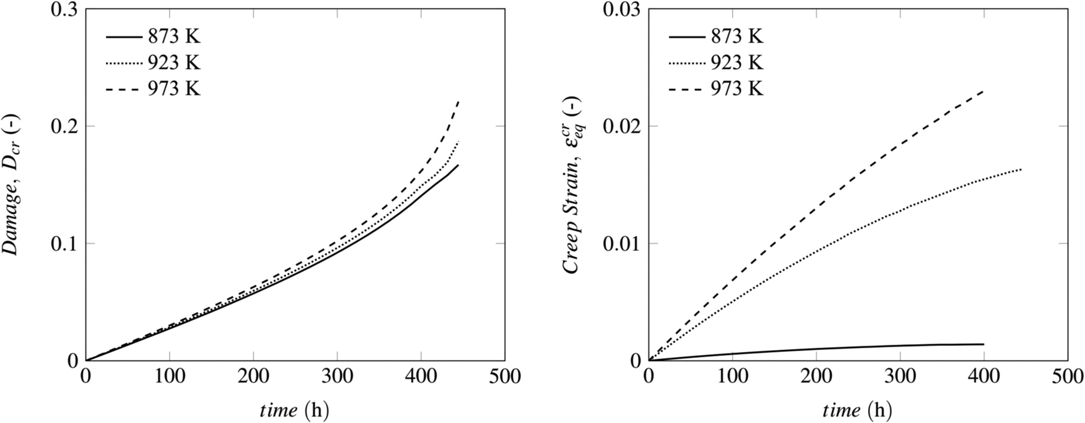
The temperature-dependent parameters allow the user to span over a wider range of (in particular to higher) temperatures, compared to those parameters of (Liu et al., 2015), which are optimized for 750 K only. As an example, creep strain and damage over time at three different temperatures and for an initial stress of 650 MPa are shown in Figure 5. It can be seen that temperature has an enormous impact on creep and on creep strain, as expected. Higher temperatures promote a much faster creep deformation. This is depicted well from the picture on the right. On the left, the damage shows again a non-linear increasing trend with time. Since the Chaboche-Lemaitre damage
Conclusions
In this paper, a method for the determination of temperature-dependent Norton coefficients for Inconel 718 was shown. The procedure takes rupture creep test data as input. The so obtained coefficients are then implemented in a User Programmable Feature inside the ANSYS APDL environment, enabling the user to write a custom mechanical model. In this study, secondary creep together with material damage and Young’s modulus reduction were combined.
The results show excellent agreement with the experimental data, strictly concerning the secondary creep portion of the tests. The UPF allows the simulation of creep damage in a wide range of temperatures, in particular up to 760°C, which are close to the temperatures typical of a gas turbine combustion chamber. This method has the potential to be extended to even higher temperatures, if creep tests are provided. The range 760–1,000°C is currently under development.
This study constitutes the foundation to explore the life of Inconel 718 structures exposed at high temperature creep, where stress relaxation, damage and creep are taken into account for a realistic representation of this coupled problem. The direct application of this USERMAT subroutine in ANSYS to MGT combustion chambers is currently under development and will be published on basis of a separate study.