
Introduction
The electric ducted fan (EDF) market evolved rapidly in recent years as a propulsion solution for scaled-down models of remote-controlled (RC) aeroplanes, where they are used to simulate fast-speed jet propulsion of full-scale aircraft. This development became possible due to the new generation of permanent magnet brushless motors that enables faster rotation speed and power density needed to produce high-speed jets. Jet speeds of currently available EDFs are of order 100 m/s which allows them to fly at speeds up to 80 m/s. This speed is at the lower end of the range used for small and regional aircraft, and further increase would be beneficial.
Integration of aerodynamic and motor components has mainly been studied for cases with open propellers (Duan et al., 2020, Köhler and Jeschke, 2021). For ducted fans, McDonald (McDonald, 2014) provided a comprehensive modelling methodology for fan and motor integration. It was shown that the maximum torque and power limits define the motor operating envelope and are therefore of primary concern. Jin et al. (2018) studied the thermal coupling effect of fan hub-to-tip ratio for ducted fan designs and have shown that lower values of the parameter are more beneficial since they imply higher power density of the motor provided sufficient cooling is available. However, the fan of interest delivers relatively low jet speed and thrust. Weintraub (Weintraub et al., 2022) studied the use of an electric motor as a boost to the conventional internal combustion engine (ICE), finding that the torque characteristic of the fan did not allow the ICE to reach its peak power and speed, and with the electric motor boost the overall thrust of the propulsion was significantly increased. The use of electric motors as boosters at peak loading (take-off and peak climb) has been widely researched, however, the use of fully electric propulsion is limited by two key factors.
First, low battery energy and power capacity is a limiting factor for aircraft range and payload, as well as intensive power discharge heavily impacting the battery life. The second, less discussed limitation is the power density of the motor itself which is sufficient to be used in booster mode or for low-speed applications only. In design, fan-motor matching lies in torque-speed space where the motor should have sufficient torque throughout the operating range of the fan at highest possible efficiency. This approach does not address spatial limitations or the aerodynamic impact of the motor, since in the torque-speed framework, the motor designer has no clear guidance for motor geometric proportions from the aerodynamic perspective.
This paper shows how the design parameters of the fan can be varied to adjust the design space of the EDF as a product, in particular at a faster flight speed. The two critical parameters for motor design are introduced. The first parameter, power per frontal area of the motor, gives an estimate for the aerodynamic proportions of the fan, namely, hub-to-tip ratio. The second parameter, speed at magnetically active radius, is a limiting factor for given motor technology. Relating this speed to the blade speed allows an estimate of the required blade design parameters, flow and loading coefficients, to achieve required jet velocity at fan exit. Considering these two parameters from both the motor and aerodynamic perspective, constitutes the novelty of the paper. It is concluded that for EDFs to be used in larger aircraft, including for passenger transportation, further technological improvements have to be made to increase motor power density per unit of frontal area and to increase maximum rotational speeds. At the same time, electric motor limitations mean that fan blade design should be adapted and compared with common practice in gas turbine driven turbo-fan engines.
Methods
A sketch of a fan driven by an electric motor is shown in Figure 1. The top side of the image is a front view of a ducted fan and the bottom side is a cross-section of an in-runner permanent magnet direct current electric motor. At steady operation, the torque generated by the motor is equal to that consumed by the fan. The former is generated by the force between rotor magnets and stationary coils when an electric current is passed through the coils in the appropriate direction. This force is then multiplied by the distance from the magnets to the axis of rotation, known in the motor industry as motor active radius or magnetically active radius.
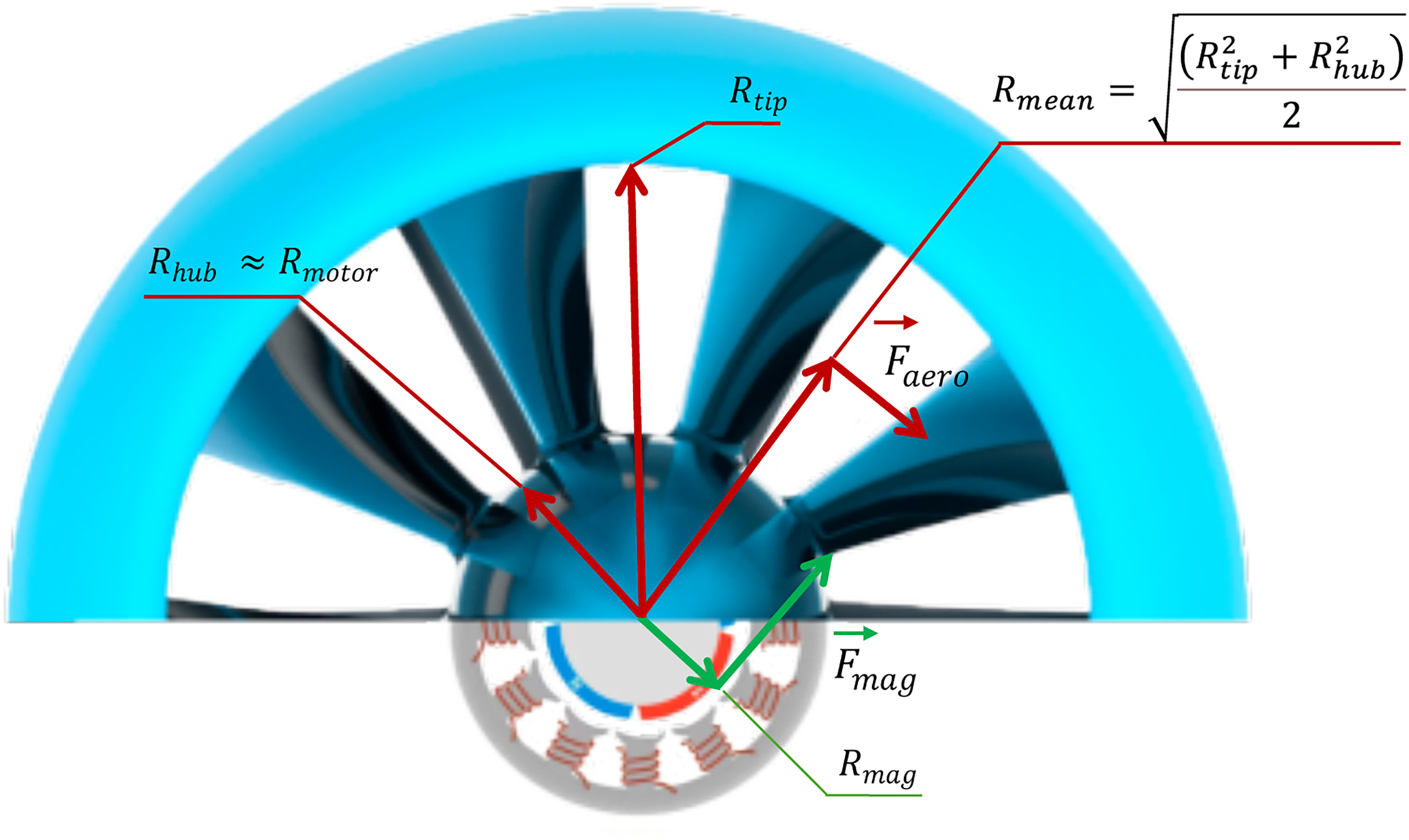
From an aerodynamic perspective, the force on each rotor blade is proportional to the work added to the air and the mass flow of that air, where the latter is the function of fan area and axial velocity. The overall proportions of the fan can be described by hub and tip radii or by one of them and the ratio between them: hub-to-tip ratio (HTR). For simplicity in the present paper, these parameters are assumed constant along the streamwise direction. The mean radius of the fan, shown in Figure 1, can be considered as the lever for the aerodynamic force. As a result, aerodynamic torque is proportional to blade circumferential velocity squared.
The torque balance between the motor and the fan can be controlled by the ratio of the magnetic gap diameter and the blade mean radius: magnet-to-mean or MTM. Therefore, two ratios are important for the joint aero-electric design of the EDF: the hub-to-tip ratio and the ratio of magnetic gap radius to the mean radius:
Later in the paper, these ratios are explored together with two other parameters – the flow coefficient of the fan (Equation 9), which characterises the mass of air to which the work is added and the length of the motor that affects its available torque.
Ducted fan design considerations
A ducted fan design methodology is provided by Casagrande Hirono et al. (2022) and also described elsewhere in the literature, for example, by Weintraub et al. (2022). This paper only provides first-order considerations to estimate the power consumption of the fan which is then converted to the motor requirements. The procedure starts with choosing the propulsive efficiency at a given cruise velocity which therefore gives jet velocity. This yields thrust and aerodynamic power per unit of jet area.
Two fan design parameters are then varied: hub-to-tip ratio and flow coefficient at mean radius. The former defines power density of the motor and using the two together gives the speed at the magnetic gap.
The following assumptions have been made to simplify the analysis. The meridional flow path is formed by two straight parallel lines at hub and casing. The area of the jet equals the exit area of the fan. Component losses are kept constant based on representative EDF performance. This includes wake losses downstream of the motor, nacelle drag, aerodynamic and electric efficiencies. Lastly, no limitations were implied to the range of design flow coefficient, even though there are known limits for optimal values of that parameter allowing for best efficiency and operating range, generically known as “Smith Chart” (Hall et al., 2012). Introducing the variability of the aforementioned parameters adds extra degrees of freedom and requires more detailed design considerations.
Hub-to-tip ratio
Hub-to-tip ratio (HTR) is used in turbomachinery applications to calculate the variation of flow parameters and blade geometry along the span. The practical range of this parameter is 0.3–0.9. At the upper boundary of that range, the difference between the magnitude of circumferential velocities at the tip and hub is small therefore uniform flow along the span can be achieved and the blades are not twisted. At the lower boundary, the circumferential velocities at the hub are 30% of that at the tip, which limits work input and requires special profiling along the span. Figure 2 shows three practical options of HTR previously seen in electric ducted fans.
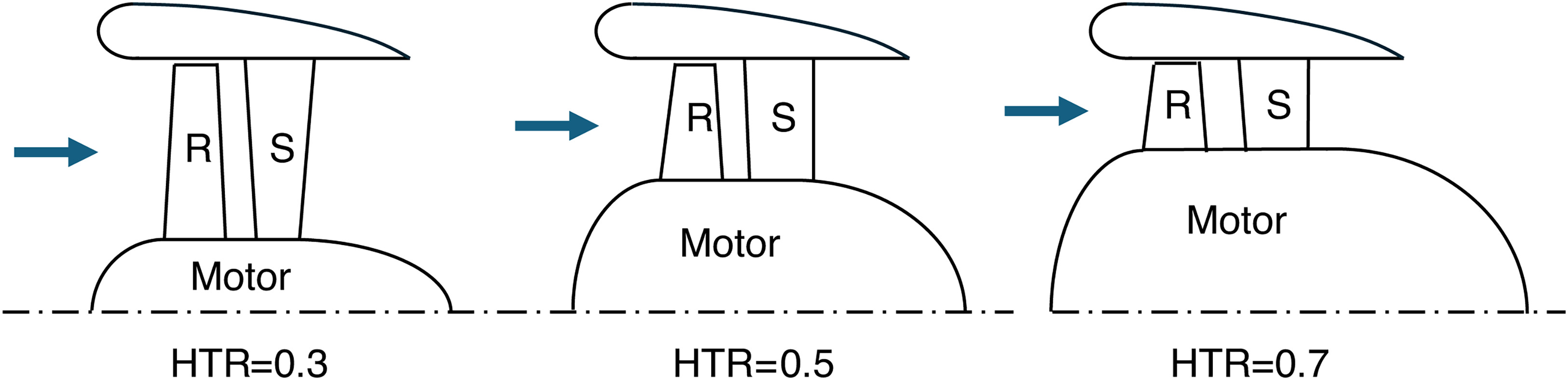
For motor-driven applications, HTR introduces two extra meanings. First, it defines the space available for the motor inside the fan hub. Following Figure 1 this defines the speed of the magnets and available torque per unit axial length. For each case in Figure 2 the length of the motor can be varied in case more torque is needed for a given application.
Second, HTR defines the motor blockage downstream of the EDF. This blockage can be diffused with a tail cone at the end of the motor, but it is most likely that there will be a wake region, particularly for higher HTR. Some portion of the blocked area can be used to discharge the cooling air from inside the motor, but such flows are negligible compared to the main jet. In further calculations, this blockage and associated losses are not considered for the sake of model simplicity. For the same reason, an area change downstream of the stator blades and the exit of the fan is not included in this analysis.
Propulsive efficiency
In Figure 2 the nacelle diameter of the three options is kept constant for clarity. However, to maintain propulsive efficiency and thrust of the fan at variable HTR, the fan area must remain constant. For higher HTR this will mean increased overall diameter of the EDF and increased weight and drag of the structure, which have to be accounted for later in the design process.
The propulsive efficiency of the fan is defined as:
With a chosen propulsive efficiency for design, flight velocity can be converted to jet velocity as:
For given jet area Aj the thrust and aerodynamic power can be calculated as follows:
In this case, the power equation already accounts for aerodynamic efficiency which is defined as:
For the calculations below the aerodynamic efficiency is assumed to be 80% to account for low Reynolds number and relatively high roughness of small scale ducted fans.
Using Equation (1), the frontal area of the motor can be obtained from the jet area of the fan, i.e. the frontal area of the fan:
As expected, higher HTR values allow more room for the motor so motor power density per unit of frontal area reduces proportional to HTR squared.
Flow coefficient
The flow coefficient is defined as a ratio of the axial velocity to the blade velocity at the mean radius. For the case where the area of the jet equals that of the fan, the axial velocity can be assumed equal to the jet velocity. This gives:
From a fan's perspective, the flow coefficient allows the jet velocity to be varied at a given motor speed therefore optimising thrust and power consumption to match the peak efficiency points of the motor. From the aerodynamic perspective, the flow coefficient controls the stagger angle (see Figure 3) of the blades and the aerodynamic loading. For the EDF working at static conditions, the loading coefficient can be defined as:
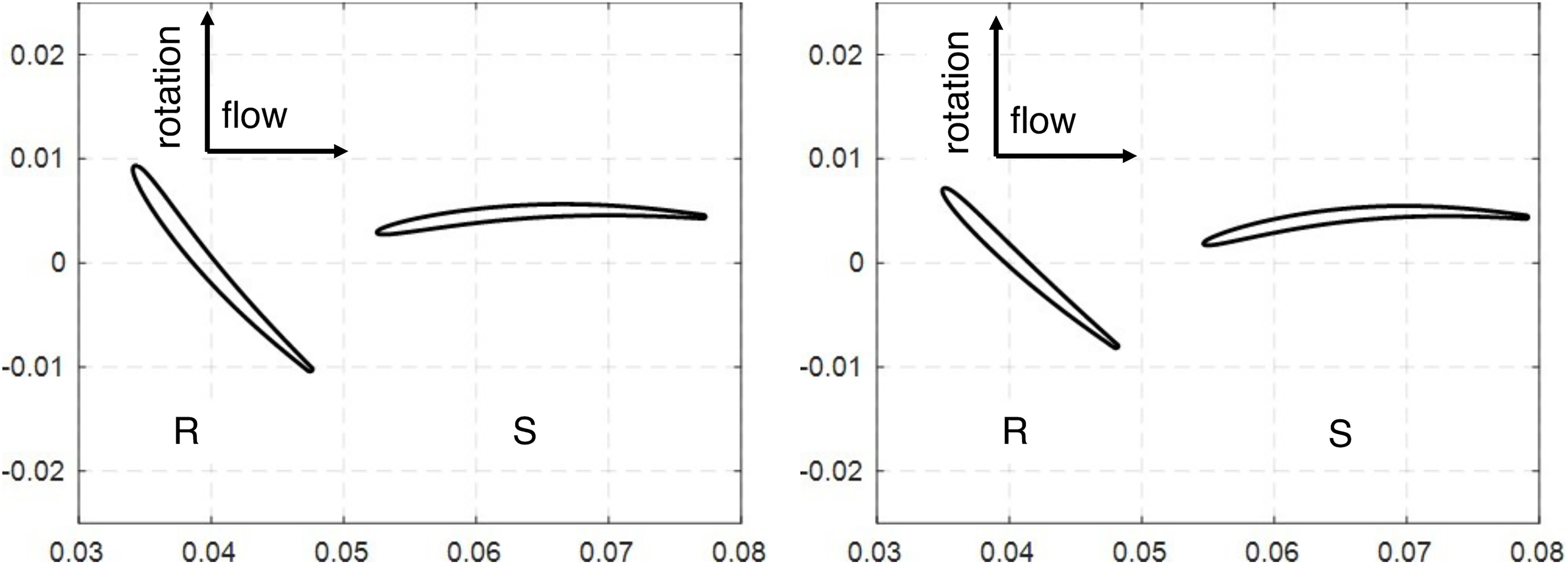
Details of flow coefficient optimisation and appropriate design metrics are shown by Casagrande Hirono et al (Casagrande Hirono et al., 2024). Only two examples of flow coefficients are shown in Figure 3: 0.4 and 0.6. Just two values were chosen to maintain the simplicity of the paper so that the effect of the flow coefficient can be illustrated, and further extrapolations can be performed by the reader if necessary.
Electric motor design considerations
Two motor design parameters are considered to illustrate how motor design limitations can affect the aerodynamic design of the fan: the magnetic gap radius and the axial length of the motor. Both parameters can be used to increase the torque output of the motors. However, the former also increases motor frontal area which affects the aerodynamic design.
Motor torque is a function of the magnitude of electric current, applied voltage, number of windings in each coil and the axial length of the motor. It is also a function of the radius at which the magnets are placed (Rmag), the magnetically active radius. The ratio of the motor active radius to the motor outer radius is a compromise. Increasing it increases the lever of magnetic forces applied to the magnets but on the other hand, it reduces the available volume for placing the coils in the stator. Higher Rmag also means higher circumferential velocities of the magnets for the same motor speed, which means higher centrifugal forces on the magnets. Therefore, special effort (e.g., fibre-glass wrapping) might be needed to retain the magnets. Reichert (Reichert et al., 2009) provided a comprehensive analysis of the magnets and coils radius proportions, and for the purposes of this study the value of Rmag/Rmotor is kept constant at a level of 0.45 for the in-runner motor, i.e. the motor with the rotor placed inside the coils (see Figure 1).
Increasing the axial length of the motor allows for higher motor torque while keeping the same motor diameters (both rotor and overall), therefore keeping the centrifugal forces on the magnets at the same level. During production of electric machines, the iron core laminations are typically stamped from silicon-steel sheets. Since the lamination stamp tools are expensive (Hendershot and Miller, 2010), electric machine manufacturers often offer different machine length variants based on the same laminations. The main limitation for the axial length of the motor is related to the stiffness of the rotor, and normally the motor length is between two and five times its outer diameter. Three axial lengths were considered: 1, 2 and 4 outer diameters.
Fan-motor matching
Torque-speed characteristics
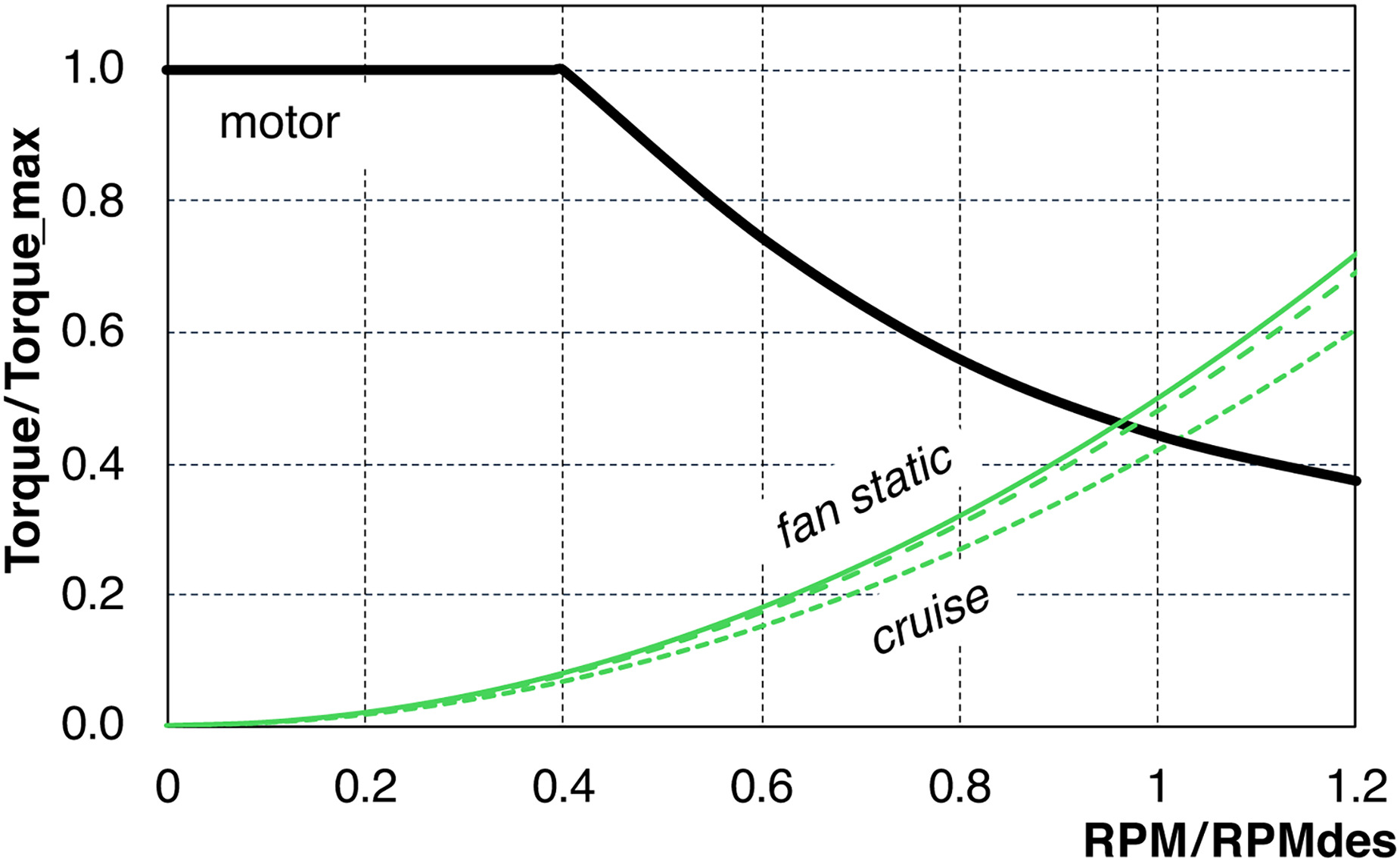
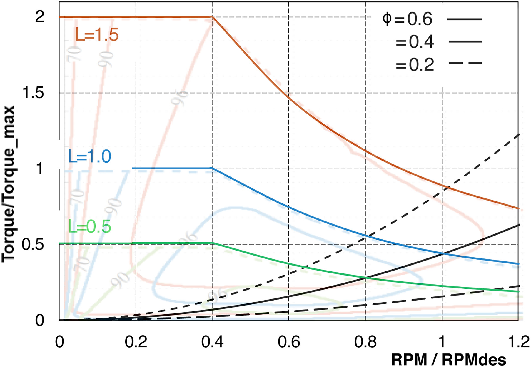
A torque characteristic of an EDF driven by an electric motor is shown in Figure 4 in parameters normalized by maximum torque and design speed respectively. The matching of aerodynamic load with electric motor is widely described, for example, Hendershot and Miller (Hendershot and Miller, 2010). The consumed torque is proportional to the rotational speed squared and the available torque is decaying after a certain motor speed. The region beyond the corner point is referred to as field-weakening range. At flight conditions the aerodynamic loading and consumed torque is decreasing as can be seen from Equation 5, where torque is proportional to the jet velocity squared multiplied by a factor proportional to the difference between the jet and flight velocities. The dashed parabolic lines below the solid one in Figure 4 show this trend. The layout of Figure 4 will be used in the next section for motor-fan matching by varying the flow coefficient of the fan and motor axial length.
Power-speed characteristics
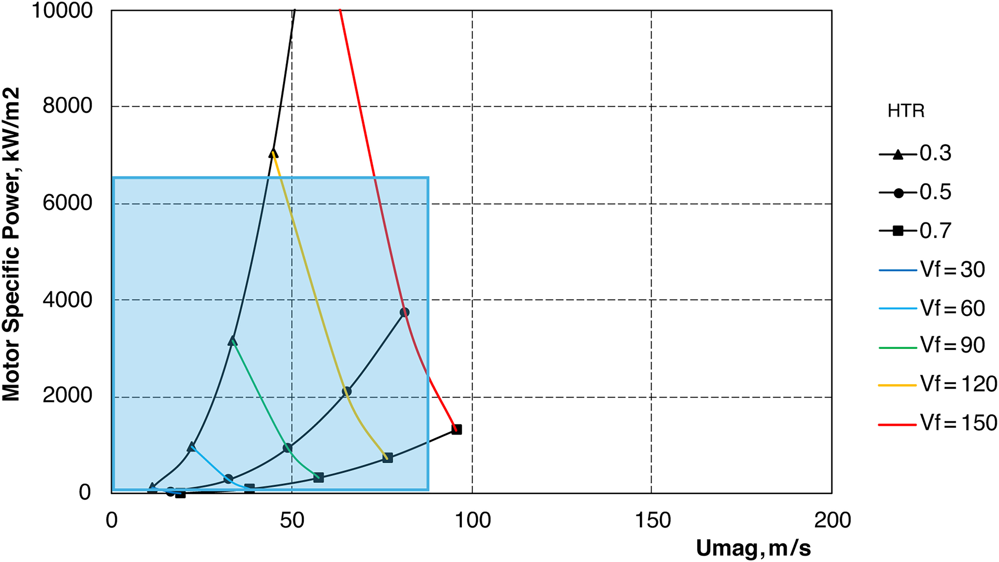
Figure 5 shows the required aerodynamic power per unit of motor frontal area. Three lines are plotted for constant propulsive efficiencies of 70, 80 and 90% at cruise conditions. The design flow coefficient for all three designs is 0.4. Coloured lines are drawn for various design flight speeds. As was shown in the previous section, known propulsive efficiency and flight speed define the jet velocity and aerodynamic power which is then converted into motor power density. The magnetic gap velocity Umag is calculated using jet velocity and the chosen flow coefficient.
Figure 5.
Required power per unit of frontal area and circumferential speed at magnetic gap for a motor of typical EDF at different flight speeds and a region of available EDF motors.
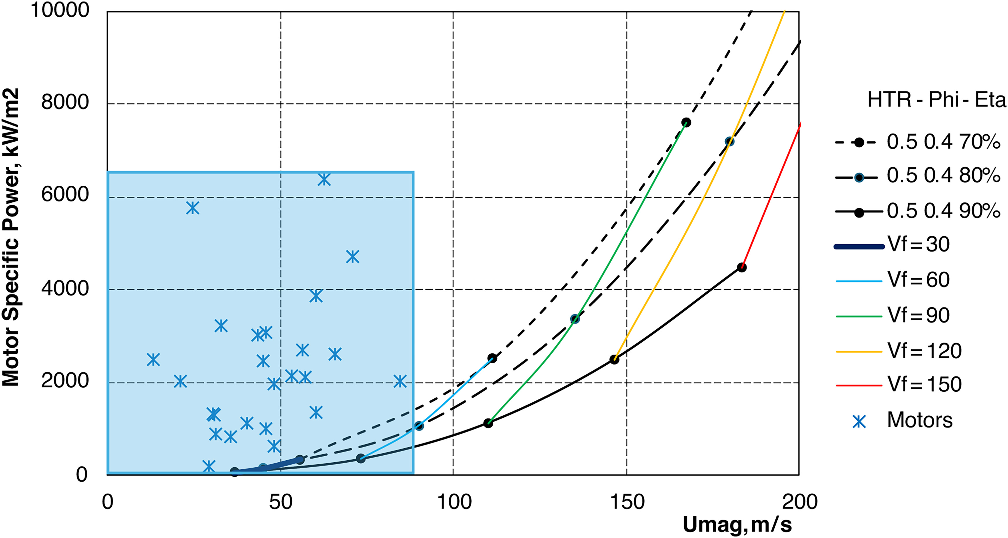
Blue stars show benchmark parameters of electric motors available on the RC market. It is observed that manufacturers offer a range of output power and rpm. However, motor parameters within this range follow the same technological trends: permanent magnet brushless motors with air cooling and magnets glued to a rotor with little or no magnet retaining elements. This technology allows circumferential speed of the magnets of 50–100 m/s and a power density of up to 6,000 kW/m2. From the aerodynamic perspective, this is sufficient for flight speeds of 60–80 m/s depending on the level of thrust required along the mission.
Relative parameters from Figure 5 can be converted to actual product performance. For example, a 120 mm outer diameter EDF with a jet speed of around 100 m/s delivering thrust of 50 N at flight speeds of 60 m/s. This requires a motor of 60 mm outer diameter with a peak power of 7–10 kW. This level is widely achieved by the hobby aviation industry. However, to achieve the speed of a regional aircraft, e.g. 100 m/s, with the same level of thrust the motor power must exceed 20 kW at around 60,000 RPM but still within the 60 mm outer diameter of the motor. This means doubling the speed at the magnetic gap as well as doubling the power density per unit of frontal area. Increasing both rotational speed and power density leaves challenges in the motor design. There are known motors that can offer such performance yet not many of them have been seen in mass and cost-effective production.
Varying fan design parameters for faster flight speeds
In this section, fan design parameters are varied to explore options for faster flight speeds.
Varying hub-to-tip ratio
Figure 6 shows motor requirements for various hub-to-tip ratios with
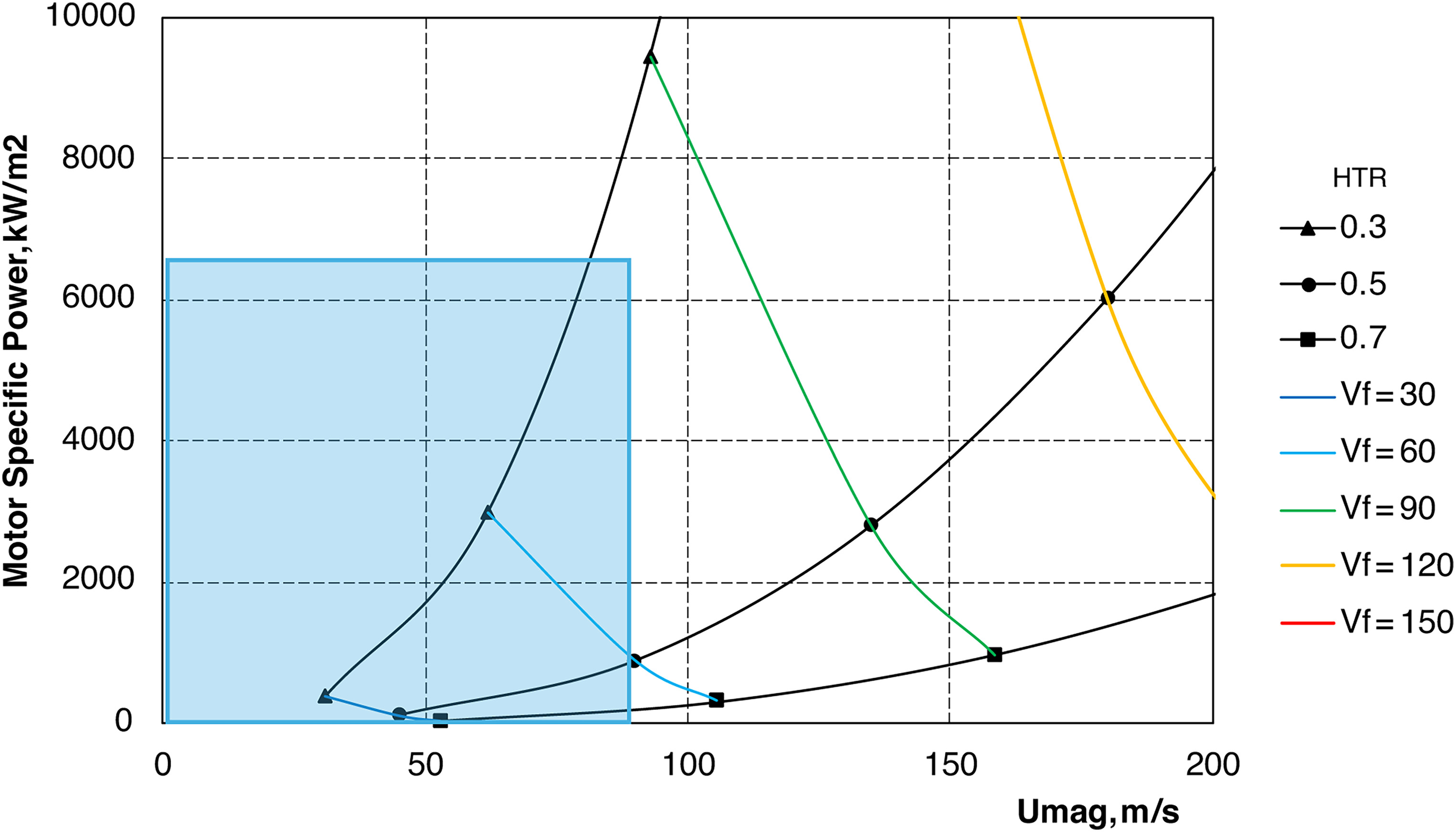
For lower HTR the motor frontal area reduces quadratically therefore increasing the required power density. At the same time, the MTM ratio is also decreasing which allows for the motor to spin slower for the same Umean of the fan.
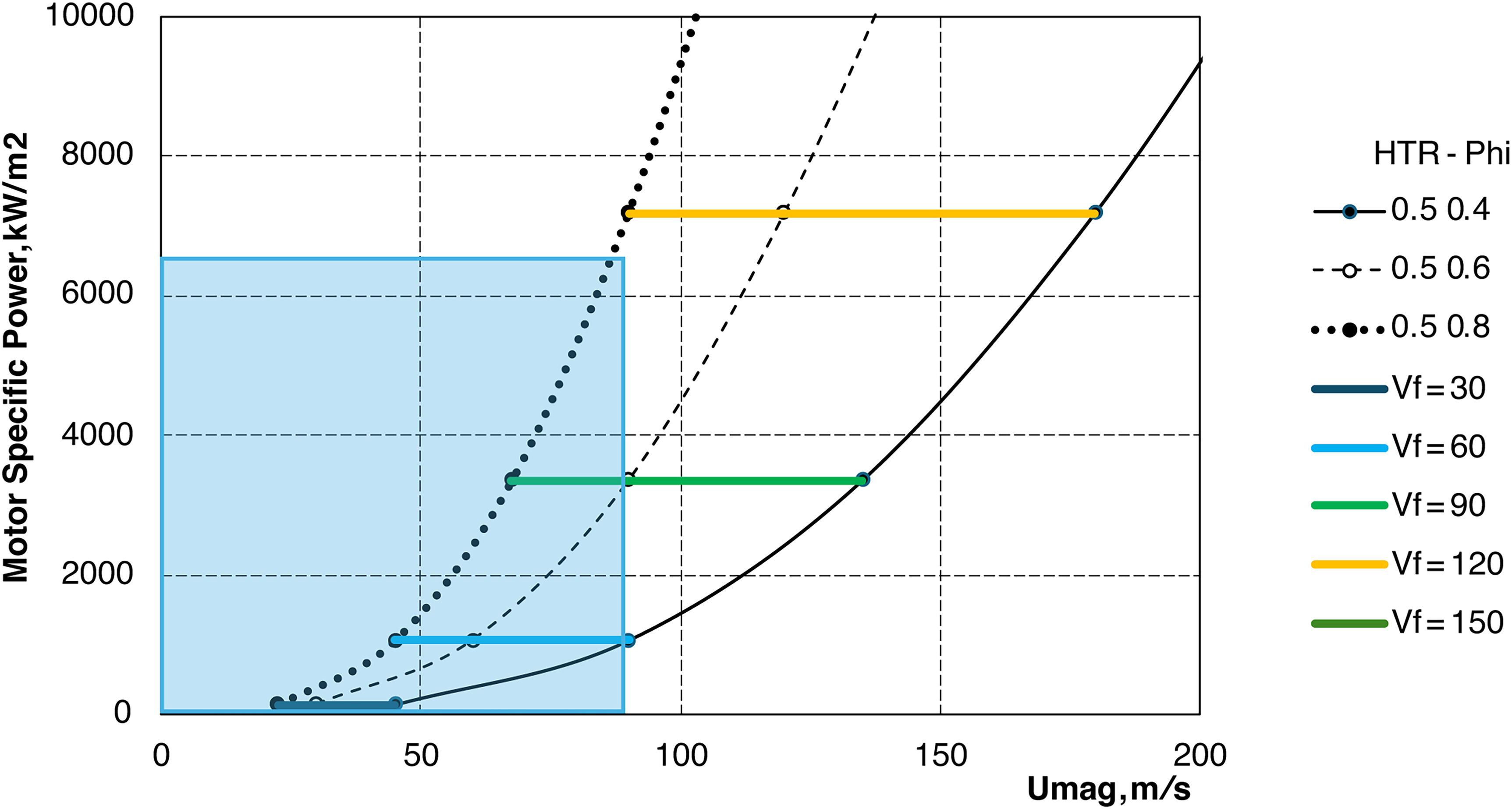
Varying flow coefficient
Flow coefficient controls the jet speed at a given motor speed. For EDF designs shown in Figure 7, the flow coefficient allows for higher jet and therefore flight velocities for a given motor design when sufficient power density is available. However, the range of flow coefficients used in the design practice of axial fans and compressors normally does not go above 0.7–0.8 at the mean radius (Anderson, 2019). This means that, for example, for a flow coefficient of 0.9 the stage loading will have to be above 0.4 which will require increased blade count and special attention to endwall flows. The range of optimal design flow coefficients also accounts for even higher flow coefficients at blade hub which is particularly critical for low hub-to-tip ratios.
Varying Axial length of the motor
Figure 8 shows the torque characteristics of the EDF with three motor lengths of 0.5, 1 and 2 times motor diameter. This allows for an increase in motor power density per unit of frontal area. With increasing length, the motor torque is increasing proportionally allowing for the fan to deliver more power to a greater flow of air. The maximum rotational speed of the motor does not change due to the radius of the magnetic gap not changing and the same technology being employed. Therefore, to accommodate increased available power of the motor, the fan needs a higher design flow coefficient as shown in Figures 6 and 7.
Extreme case: reaching 150 m/s flight speed
Further increase in flow coefficient together with higher propulsive efficiency can allow high flight speeds up to 150 m/s with the current mass-market technology level. Figure 9 shows that to do so the flow coefficient must be 0.9 and the propulsive efficiency should be 90% or above. This would allow the fan with HTR of 0.5 to reach sufficient jet speed to fly at 150 m/s. However, the two limitations must be considered when going for such high parameters.
Figure 9.
Fan parameters to achieve flight speeds of 150 m/s with available mass-market electric motors (η prop = 0.9 ϕ = 0.9
First of all, high propulsive efficiency means low delta between jet and flight velocities (see Equation 3), hence, low specific thrust per unit of frontal area. Delivering required thrust with high propulsive efficiency leads to large jet areas and therefore higher weight and drag of a single nacelle, or use of multiple engines. The second is the limitation in the design flow coefficient which was described in the section above. As a result, the aerodynamic configurations of the fan shown in Figure 9 can be hard to achieve and might have lower-than-expected aerodynamic efficiency.
Discussion
The design parameter study shows how the aerodynamic design of the fan can be adjusted to match the electric motor. The extreme case in Figure 9 demonstrates that for faster flight speeds fan design parameters might be outside the optimum range. In particular, the flow coefficient needs to be at levels of 0.9 and above, which can stretch other aerodynamic parameters to achieve high aerodynamic efficiency.
On the other hand, Figure 10 demonstrates the trend in motor development for faster flight EDF applications. In this case, the aerodynamic parameters are kept in the optimum range known from the compressor stage design practice. The flow coefficient is taken in a range of 0.5–0.7 (Hall et al., 2012; Anderson, 2019). And the hub-to-tip ratio is 0.4–0.6. Also, to broaden the scope, the propulsive efficiency is taken as 80% and 90% for the cases of least and highest power consumption respectively.
Figure 10.
Trend in electric motor requirements for optimal fan design parameters range (η prop = 0.8 − 0.9 HTR = 0.4 − 0.6
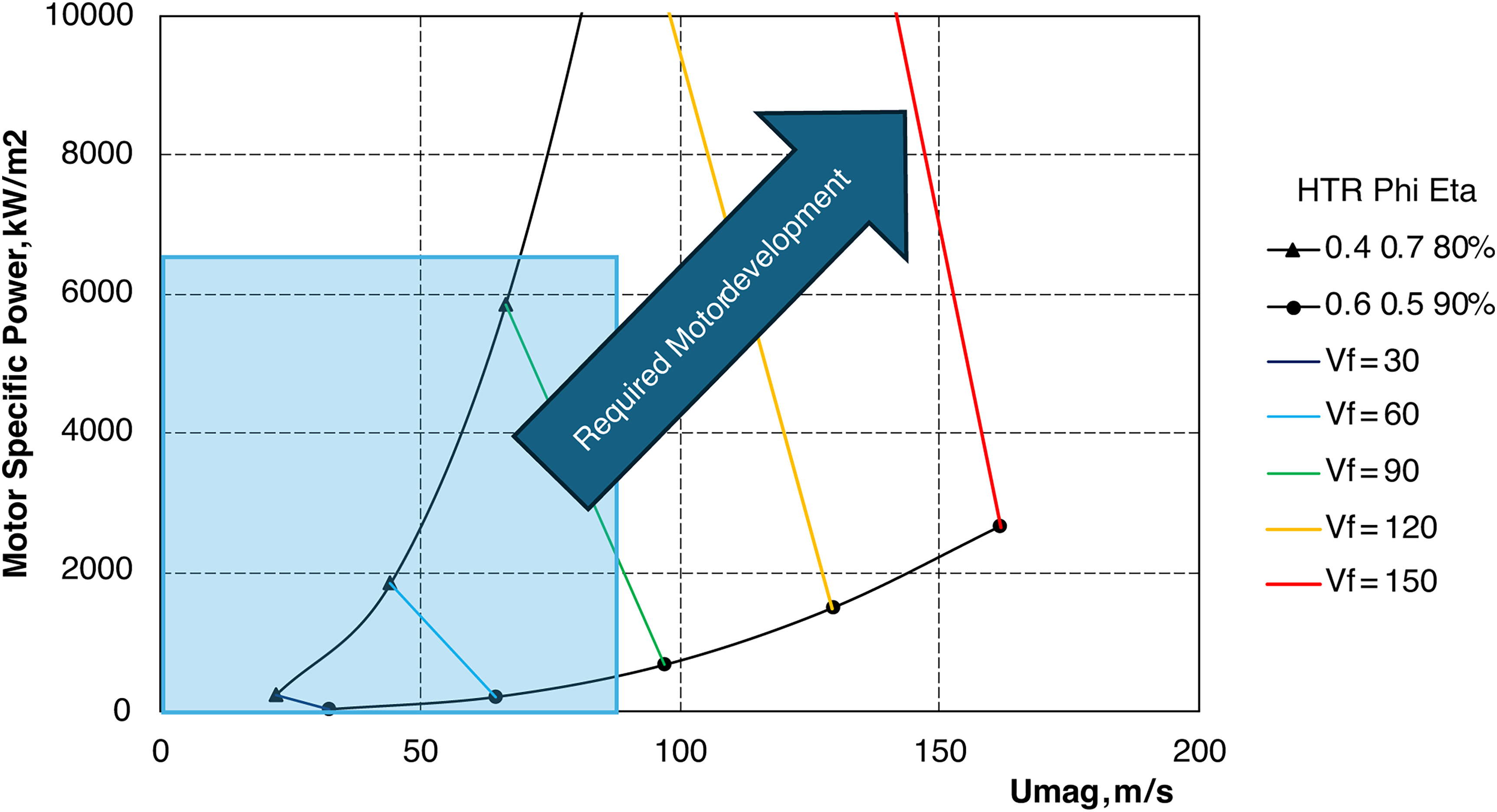
As a result, the area between the two black lines in Figure 10 shows the desired electric motor configuration for the best aerodynamic efficiency of the fan, and the coloured lines represent the flight speed of the resulting propulsor.
At first glance, this trend shows that for every percent gain in achievable Umag quadratically more power density can be consumed by the fan. However, this should be treated with care as the motor cooling is not considered in the current paper. It is known that for air-cooled motors a cube-square thermal scaling law is applicable (Moore et al., 2023), yet it can differ with the type of cooling. This limits the power density of larger motors as the outer area grows with the square of the motor diameter, but the volume of the motor and therefore the heat generation is proportional to the diameter cubed. Therefore, high power densities per frontal area might not be achievable at a larger scale. Then the trend in motor development could go towards faster rotational speeds via enforced magnet retaining technologies.
Figure 10 also shows how the real inputs for the motor design can be chosen. Such parameters are of great importance for motor manufacturers: outer diameter, speed, and power of the particular motor entering the market. Figure 10 can be used to estimate these parameters for the required flight speed and thrust of a particular aircraft.
Conclusions
For high-speed electric ducted fans, the current technology level of electric motors causes the fan design flow coefficient to be increased compared to conventional values. This allows for highest possible jet speed and adds the highest possible aerodynamic power at a limited rotational speed of the motor. Another compromise to be made at the system level is the fan hub-to-tip ratio which distributes the frontal area of the EDF between the electric and aerodynamic components. Lower values require higher levels of motor power density which is limited by heat dissipation capabilities. Increasing the HTR causes higher losses at the wake downstream of the motor and also leads to higher magnetic gap speed of the motor which is limited structurally.
This paper has shown that there are two critical motor parameters from the aerodynamic perspective. In addition to the specific power-to-weight ratio, commonly used in power train considerations, the power per unit of frontal area and the operating rotational speed are of great importance. As a result, with the current mass-market technology level, the flight speed of a vehicle with electric propulsor can be in the order of 80 m/s. This level can be sufficient for a regional aircraft, however, the design space for larger, faster aircraft will require a 100–200% increase in jet speeds and a linear increase in both the power per unit of frontal area and the circumferential speed of the magnets.