
Introduction
With the increasing demand for higher gas turbine efficiency, the design margin allowed by existing manufacturing processes is constantly squeezed. To open up new design space, Siemens has been exploring metal-based additive manufacturing (AM) technologies such as selective laser melting (SLM). In general, these processes make a part by melting metal powder layer by layer using a high energy density heat source. Comparing to the conventional subtractive manufacturing processes, the metal-based AM processes are capable of producing radically different designs like lattice structures and internal winding channels. The new design space can be leveraged to solve engineering problems that are otherwise highly challenging. Moreover, since the AM processes work directly with the 3D model and produce near-net shapes, the design-to-product process chain is shorter than conventional manufacturing methods. This allows rapid prototyping and manufacturing that are critical to the fast design iterations. Due to these unique characteristics, metal-based AM processes have the potential of significantly reducing product cost and lead-time, especially for parts with relatively smaller batches.
However, the wide adoption of AM in gas turbine product development is quite challenging mainly due to two reasons. First, the strict design requirements call for solid understanding of the designated AM process and material properties. However, the AM process development and material characterization workflow is lengthy and costly given limited existing knowledge. In addition, Siemens internal experiments have shown a strong specificity of the workflow to a particular process and material configuration. When the configuration changes, the workflow need to be largely reworked. Moreover, related to serial production, there are several unknowns such as how to effectively set-up serial production, the capability of the machines for 24/7 operation regime, repeatability, and many more. Second, AM has not been well perceived by the design community in terms of the capabilities and limitations. This causes ineffective and sometimes incorrect use of AM in design. To bridge the two gaps, Siemens has developed two streamlined frameworks to expedite the AM industrialization. The first framework focuses on the more efficient process and material development, and the second framework defines a new design paradigm that maximizes the AM awareness in design.
The article will elaborate the two frameworks in the next two sections. Then a few Siemens gas turbine applications will be provided to demonstrate the frameworks. The benefits of the metal-based AM technologies will be validated through these use cases. The contribution of the article will be summarized in the conclusion section.
Process and material development
For novel manufacturing methods like AM, typically obstacles arise when processing new materials and new components, or new machines are taken into operation. In particular, for AM the required individual specific strategies and standardized approaches for materials qualification as well as for process qualification are still missing 7. This, however, is highly required when considering that for each material or material derivative the AM process must be optimized individually for the used AM machine(s) 25. Since optimization and qualification efforts require considerable time and expenses, Siemens AG has established cross-divisional competence centers for joint material and process development. To this end, the Power & Gas division operates a network of various AM systems at different sites. These sites include the Berlin (Germany) and Finspång (Sweden) plants as well as Materials Solutions — A Siemens Business in Worcester (UK) and corporate research units.
The following section presents examples of how standardized process qualification and material data generation for AM is carried out within the division Power & Gas.
Standard qualification job
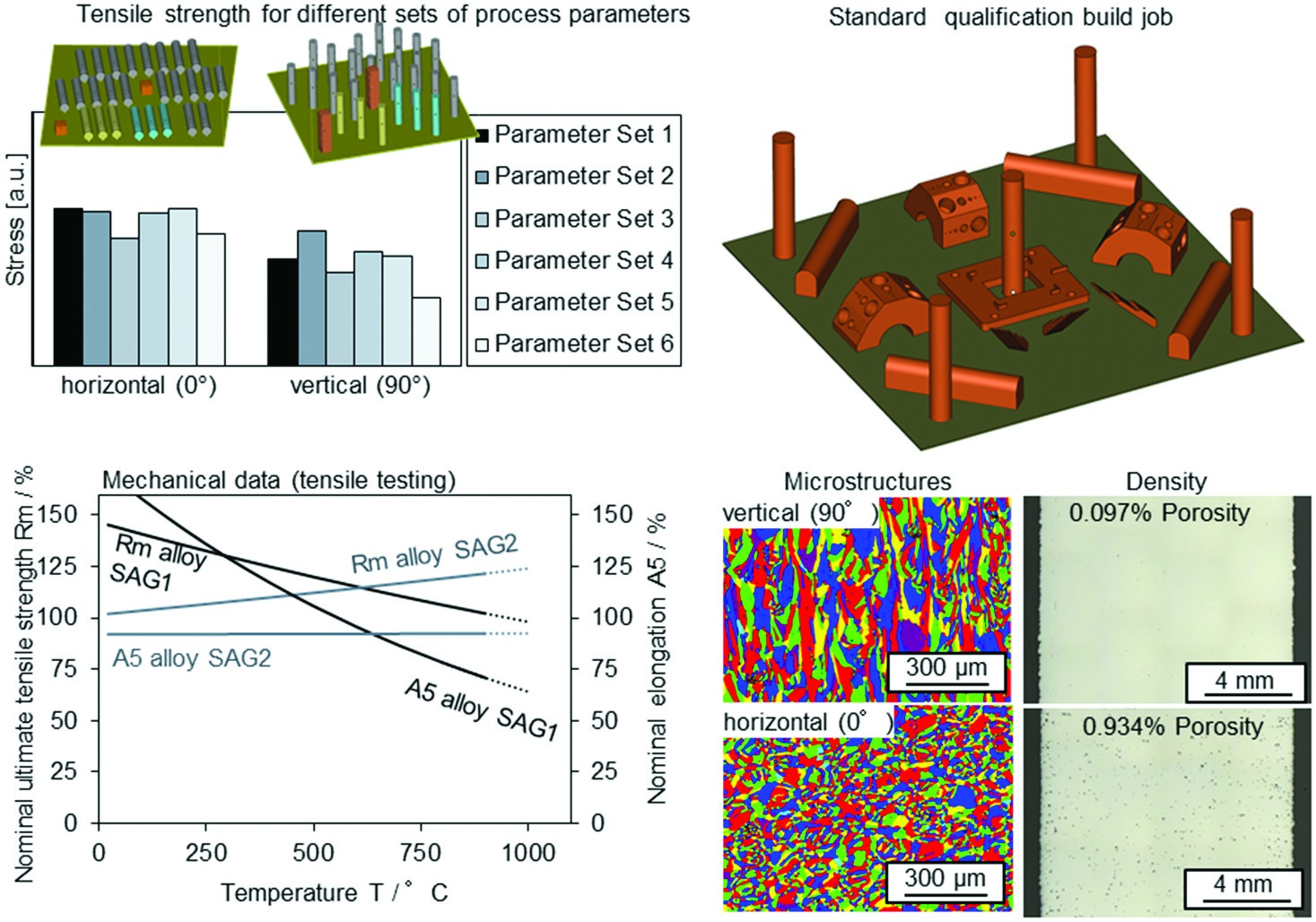
With a growing number of different SLM machines, part suppliers, and processes, a method for consistently comparing build quality became essential. A standard qualification job (Figure 1) was developed to reflect the different characteristics Siemens found necessary to build suitable SLM geometries. The build quality can be impacted by a combination of process variables, such as raw material (powder), recoater type, shield gas flow, laser parameters (and layer thickness), and scaling factor. The geometries within the build are specifically designed and positioned to test for possible issues resulting from these variables or a combination of these variables.
A bulk sample with holes of different diameters at the different angles is built once in three orientations, rotated about the z-axis. White or blue light scan is used to evaluate these geometries for inaccuracies that can be attributed to inadequate laser parameters or recoater type.
Roughness is measured on samples with upward and downward facing surfaces at different orientations rotated about the z-axis. This gives an indication of both the surface laser parameters and the interaction of the surface relative to the recoater.
Bulk horizontal and vertical samples are built in the corners, as well as, in the middle of the build to gauge multiple characteristics in different positions within the build. The samples are measured for porosity, defect density, basic mechanical properties and roughness. These samples are meant to address any issues concerning shield gas flow (which can result in increased roughness and porosity), laser parameters, layer thickness, and raw material (powder).
Lastly, a scaling part with CMM (coordinate measuring machine) features and a defined position is measured using CMM to check the scaling factors.
Together these geometries ensure the build characteristics of dimensional accuracy, roughness, porosity, defect density, microstructure and mechanical properties, meet the requirements as stated in the process specification for the material process 13.
Standard comparative mechanical testing
The significance of process deviations is constantly evaluated with the assistance of mechanical testing. The capability to build a database of properties using quick and inexpensive testing is critical for studying the effect of process variables on the performance of the materials. Standardized mechanical testing is employed as a tool for the process of parameter optimization, process qualification and continuous process monitoring. Room temperature tensile testing is used for testing in qualifications and process condition comparisons (Figure 1). For process monitoring of specific component production, elevated temperature tensile testing is used in the range of the application temperature. This more specific testing supports the robustness of the data in a relevant temperature regime.
Microstructure
Microstructure investigations provide additional insight into the mechanisms causing variances in mechanical property results. The microstructures resulting from the SLM processing of alloys used in gas turbines are typically fine elongated grains that can recrystallize during heat treatment depending on the alloy (Figure 1). In case of recrystallization, the resultant structures from heat treatment are ideally equiaxed and isotropic. In case recrystallization does not occur, an anisotropic material remains. As a result, obtaining mechanical properties is more complex, and hence, costly. Statistical measures of grain orientation and grain size distributions are obtained using EBSD (electron backscatter diffraction). These values are then tracked to ensure proper heat treatments and satisfactory processing. Additional characterizations are carried out dependent on the possible phases within the alloy.
Design data generation
After a successful process qualification, the process is usually “frozen” and documented in process specifications. This includes not only the AM process itself but also the powder materials characteristics as well as post processing steps such as heat treatments. These specifications are important for the internal quality management and for supplier qualification. Material data generation programs based on these specifications are carried out to build a solid database that allows tools used by the gas turbine designers to perform design and lifetime calculations.
Since gas turbine components are exposed to various operating conditions, material data over a wide temperature range is required. Depending on the material and its potential applications in a gas turbine, this not only includes simple static strength values but also creep and stress rupture data as well as fatigue strength under different load conditions for LCF and HCF stresses.
Such comprehensive material data generation may take anywhere from several months to multiple years due to the variety of data necessary. The resulting costs can be several hundred thousand euros up to 1.5 million EUR 14. Considering that, the joined development approach within the Power & Gas competence center is an important enabler for significant cost savings and accelerated development.
Design for additive manufacturing
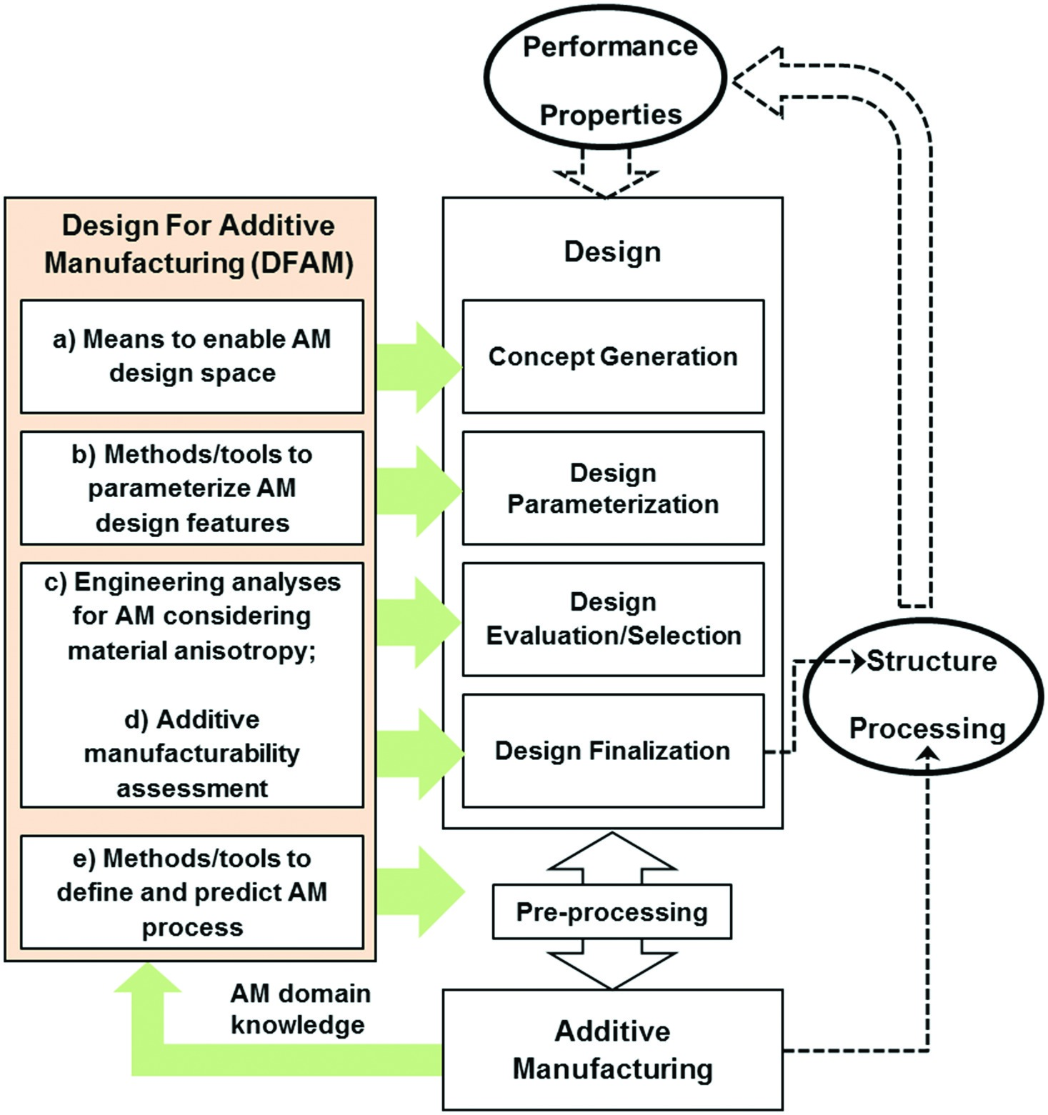
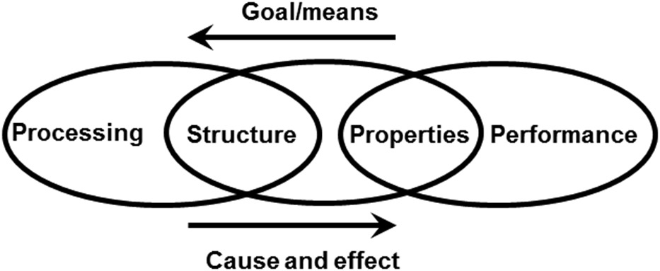
Design for Additive Manufacturing (DFAM) is the study of design approaches and tools that aim to maximize the AM awareness in design. This is critical to unveil the new design space to the designers. However, the current product design processes and the CAD/CAE/CAM tools have been tailored for conventional manufacturing methods, and are incapable of enabling AM in design stages. More importantly, DFAM demands for a design mind-set evolution to allow design teams break through the traditional ways of thinking of and making new parts. To overcome these hurdles, comprehensive DFAM frameworks have been proposed 20, 9, 11 to capture the technological needs to enable AM in design. A three-link processing-structure-properties-performance process chain (Figure 2) developed by Olson 16 is often adopted to construct the frameworks. In the context of design and additive manufacturing, the “performance” is the engineering targets that a design problem needs to meet, such as the structural and weight requirements for a gas turbine vane design. Based on the performance requirements, a set of part “properties” (e.g., mechanical and thermal properties) are derived. Given the “performance-properties” link, the detailed design and analysis is conducted to define the “structure-processing” link. The “structure” is the optimal part design that meets the performance requirements. The “processing” refers to the AM process selected to make the part. Note that the “structure-processing” link also infers that the design should be optimized for the designated AM process. Therefore, the “Goal/means” in the model represents the complete design-to-AM workflow. The successfulness in this direction dictates the quality of “cause and effect,” which is the realistic engineering response of the structure and is often to be observed through testing and validation.Based on the process chain model, we propose a DFAM framework that is tied to a generic design-to-AM process generalized from the Siemens gas turbine design process. As shown in Figure 3, the idea is to identify the gaps between AM and design, and to close the gaps by introducing ad-hoc DFAM solutions that meet the design needs in all design stages. Casting the closed loop design and AM process chain to the model in Figure 2, we can see that the framework embodies the performance-to-processing “goal/means” with five DFAM tasks, and integrates them seamlessly into the product development workflow. In the embodied framework representing a realistic design problem, the “performance” and “properties” in Figure 2 are essentially the input, and the final design and the optimized AM process are the instantiations of the “structure” and “processing.” In the following, we will elaborate the five tasks in DFAM framework in the context of design-to-AM gas turbine product development.
Concept generation
In this stage, the design problem is well understood by designers. Based on the knowledge and experience, a variety of embryonic design concepts is explored to address the design problem. It is critical to ensure that the full AM design space is captured in this stage. However, due to the lack of understanding of and experience with the new design freedom enabled by AM, it is often quite challenging for designers to break through the design boundaries imposed by traditional manufacturing methods. To overcome these hurdles, a set of means are proposed in task a) to evolve the designers’ mind-set to AM and to allow the effective exploration of the AM design space:
DFAM training
A systematically developed training program should be in place to educate design teams the fundamental of additive manufacturing technologies, including the capability, limitations, and design considerations. To support the training, an AM design guide extracted from the best practices for a particular AM process needs to be set up. The design guide should ideally provide easy-to-understand design rules that collectively define the AM boundary. One design rule can be that the minimum wall thickness should be greater than a certain value. Case studies are often a more productive form of training as they demonstrate DFAM through realistic design problems.
Effective exploration of AM design space
To facilitate the generation of AM-friendly design concepts, various AM design features have been developed, including cellular structures 8, 26, 19 such as conformal lattice structures (CLS) (Figure 4), honeycombs, foams, and functionally graded structures (FGS) 17. Ongoing research has been focusing on establishing the mapping between these structures and their properties, and lattice structures have shown considerable advantages in producing lighter yet stronger designs 8.

In addition, topology optimization is often used to automatically identify the optimal topological design in terms of a design objective (e.g., minimum weight; maximum strength) within a design space bounded by a set of design constraints (e.g., performance requirements such as stress and deformation to satisfy) and manufacturing constraints. For metal-based AM technologies, the manufacturing constraints can be extracted from the AM design guide. For example, the overhanging angle and the wall thickness are common manufacturing constraints to impose. Some commercial tools such as Simcenter 3D 23, HyperWorks 3 and AutoDesk Within 5 are available for stress-based topology optimization problems. In cases of gas turbine hot gas path components, thermal based topology optimization is often desired, which needs further research to industrialize.
Design parameterization
After the initial design exploration, a few concepts are generated and validated in terms of AM feasibility. The next task is to parameterize the concepts in the CAD environment, and the results will be high-fidelity 3D models for later analyses. DFAM task b) in Figure 3 focuses on efficient ways of modelling AM designs. This is necessary in that the current B-rep based CAD modelling functionalities are not suitable for creating sophisticated AM structures, and the resulting CAD files becomes too cumbersome to be practical when the complexity of AM designs increases.
The topology optimization solvers mentioned previously also provide geometry smoothing that converts a raw topology to an organic design that can be used in later analyses. For lattice structures, nTopology 15 offers dedicated tools to create and analyse sophisticated lattice designs. Recently Siemens PLM released the convergent modelling in NX11, which allows direct geometric manipulations on facet models such as STL files that are widely used for AM. This will eliminate the erroneous conversion of STL to B-rep. To enable the full potential of AM, the industry has been driving the development of a new 3MF AM format 2 that aims to preserve the full-fidelity 3D models along all design and AM stages.
Design evaluation/selection and finalization
The in-depth engineering and manufacturability analyses are performed in the two stages in order to converge the design candidates to an optimal final design. DFAM task c) and d) are proposed to ensure that the engineering analyses are adapted for AM processes, and the AM manufacturability considerations are incorporated in the final designs. For the engineering analyses, a fundamental distinction of AM from traditional manufacturing processes is the material anisotropy. This means that the material properties along the build direction are not the same as the other two directions. The material properties for AM need to be characterized for a particular AM process like SLM using the process and material development framework introduced in previous section, and the material data used in the CAE analyses should be updated to reflect such anisotropic behaviour. As an example, NX provides an interface for defining the anisotropic material properties in the CAE environment.
The additive manufacturability assessment in task d) requires the close inspection of a design in either 3D CAD or 2D drawing format against the AM considerations specified in the design guide. One example is given in Figure 8 (refer to the “Applications” section), where design changes like overhanging angle controls and gothic arches are implemented to avoid the use of support structures and potential failures in the SLM process. In addition, AM build time and build cost should also be analysed in order to understand the economic benefits of AM over other manufacturing methods. Since the complete assessment is iterative and sometimes tedious, automatic DFAM checks are often more efficient and effective in capturing the DFAM issues, especially in small and hard-to-access design regions. Some commercial tools are available that perform manufacturability checks on 3D models 18, 10. These tools do not rely much on designer’s experience, therefore see potential to significantly improve the design quality and expedite the manufacturability assessment iterations.
Pre-processing
Pre-processing refers to the activities associated with the preparation of the final design for AM process. In general, the 3D model is converted to the STL format, and the resulting geometry is positioned on the build platform. If needed, support structures are generated to prevent collapse of material during manufacturing, and any build issue identified is fixed. Once the geometry preparation is complete, it is sliced into layers and the slicing data is then loaded into the machine to start the AM process. Note that after the earlier AM-aware design stages enabled by the DFAM framework, much less geometry-related modifications are expected in this stage. The commercially available pre-processing solutions like Magics 12 and NetFabb 4 have very well streamlined this process.
However, one still needs to be careful with the AM process-driven material behaviour that may lead to unexpected geometry deviations. For SLM, such deviations are often caused by the excessive thermal stress built up during the laser melting on each layer. The thermal stress can lead to significant thermal distortion when the geometry is not stiff enough (e.g., long thin wall structures orthogonal to the build direction). If the thermal stress exceeds the fracture toughness of the material, there may be micro cracking in the structure. To capture these issues in design, DFAM task e) is proposed that focuses on the physics-based simulation of the AM process and the prediction of the material behaviour with a reasonable accuracy. Different simulation packages such as PanComputing 6 and 3DSim 1 have been developed for commercial use, and more attention is needed in the investigation of existing and new algorithms.
Closed loop design and AM process chain
The proposed DFAM framework defines and integrates five tasks to address the needs of additively designing the large gas turbine components. As it is closely tied to the Siemens gas turbine design-to-AM process, the framework provides an interface for the AM feedback to be seamlessly accessed by the designers. As the DFAM considerations are crystalized from the AM domain knowledge and best practices, the DFAM framework closes the loop of design to AM, and has been an enabler to the AM-driven gas turbine product design.
Applications
In this section, we use Siemens gas turbine applications to demonstrate the AM process and material development framework as well as the DFAM framework. The benefits are highlighted in the subsections.
Fast technology validation
The pace of innovation is a key competitive advantage in the development of gas turbines. Due to new and additional design space, AM offers high potential for the gas turbine manufacturing and development and therefore, AM can substantially contribute to achieving efficiency goals and emission targets. On the one hand, innovative design approaches are possible through using AM. On the other hand, the lead-time of product development cycles is reduced significantly because AM can provide functional prototypes that can be implemented and validated in short timeframes. Compared to the traditional approach in product development, substantial efforts for tooling are not required. Using AM as a vehicle for fast technology validation leads to abandonment of traditional and sequential development processes. Now, testing and validation of new concepts are fully integrated in the development process and not just the final verification stage. This approach allows for significant reduction of both development risks and development costs. Furthermore, this is directly associated with a paradigm shift from conservative product development with moderate development targets to much more ambitious goals.
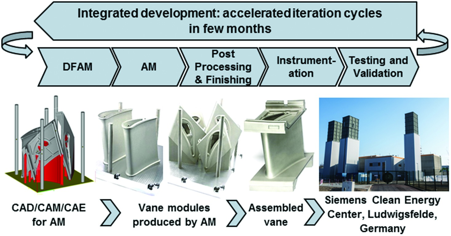
Figure 5 schematically shows how AM is used as an enabler in the product development for SGT-4000F turbine vanes with innovative cooling concepts. For this purpose, a modular approach was chosen to account for processing reasons. As shown, airfoil and blade platforms were manufactured separately, and later on assembled to the final vane using high temperature brazing processes. In Siemens test facilities (Clean Energy Center, Ludwigsfelde, Germany), several vanes with different cooling concepts were validated under real conditions, so that the results were directly incorporated into the next design iteration. By using AM as an enabler for the validation of new vane cooling concepts, the development cycle time was reduced by more than 75% compared to the conventional route.
Rapid repair and spare part on demand
AM has considerable potential in the service business of gas turbines for both repair of certain components and manufacture of spare parts. In fact, the burner tip repair for Siemens gas turbines of the type SGT-700 and SGT-800 is the first commercially established method of repair in industrial gas turbines using AM 14. During operation, these components suffer from thermomechanical fatigue, damage and wear especially to the tip. The conventional repair procedure required prefabrication of a large portion of the burner tip that was then simply used for replacement after specified operation time of the burner. The entire repair route was time consuming due to a large number of sub-processes and inspection steps. Now, just the damaged areas of the burner (about 20 mm) are removed and new material is built up on top of the burner body by AM (Figure 6). To adapt for these repair scenarios, AM machines were tailored in the Finspång plant (Sweden). The machine interior was enlarged to accommodate the full burner (800 mm in height) and both software and control modifications were installed in addition to an optical measurement system, which allows for proper adjustment of the burner body in the working plane 14.
The newly implemented repair route via AM is about ten times faster than the conventional procedure, as it avoids quite a few manufacturing and inspection processes 14, 24. This significant shortening of lead-time results in significant cost savings, too. Minimizing the repair zone just to the burner tip also results in increased resource efficiency in terms of materials and energy. In addition, with the help of AM, upgrades to the burner tip may be introduced easily. This enables a major customer benefit: depending on the type of burner and customer requirements, now the appropriate burner tips can be built on the existing burner body, including even a modification or upgrade to the latest burner technology. Here, the advantages are similar to cases with completely new designs, and indeed it is possible to benefit from the DFAM approach 21.
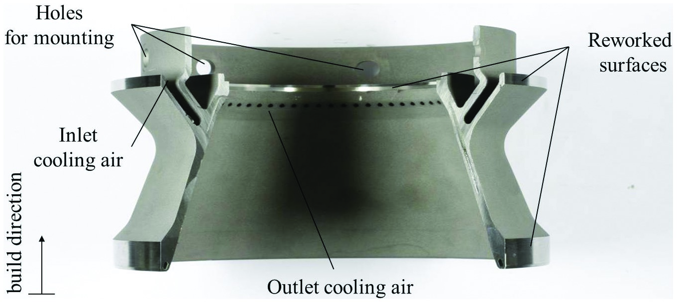
Figure 7 shows an axial swirler for the pilot burner of the Siemens SGT-1000F combustion system made via AM. Previously, such components were produced by investment casting. Instead of re-qualifying the existing cast vendor or undergoing a full qualification of a new vendor, the choice was made to produce the swirler by AM. Since the annual demand of this component is comparatively low and may vary greatly, business case calculations clearly proofed benefits for changing the production technology to AM.
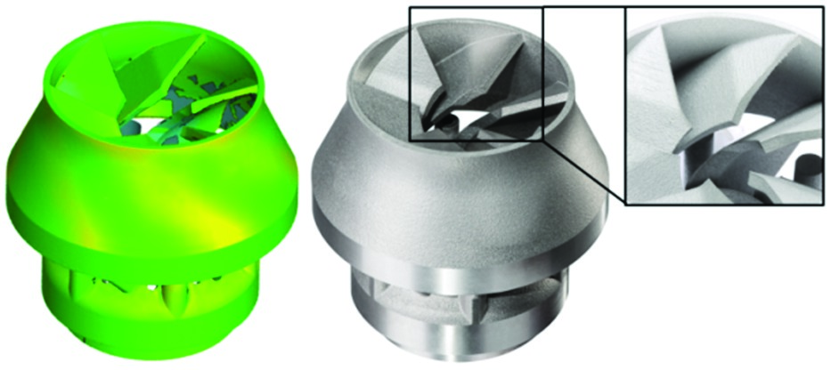
However, before such swirlers could be inserted into a customer’s machine for the first time, a multi-stage qualification process had to be in place to ensure that the components and the AM production route meet the necessary quality requirements. Prior to this qualification process, a comprehensive materials and process development program (see corresponding section) was carried out so that mechanical, physical and rheological data of the Ni-base alloy were available and could be implemented into lifing calculations for the component. The actual qualification process followed the Siemens specifications and standards and proven Six Sigma methods to guarantee process quality and stability. Similar to casting, a reasonable number of swirlers produced via AM under representative conditions were subjected to non-destructive and destructive testing as well as metrological validation. It is noted that the additively manufactured swirlers all show just very slight deviations from the desired geometry (< 0.2 mm) which is even less compared to the cast part. After having successfully completed the full qualification, the entire processing route was “frozen” and appropriate quality assurance measures and inspection plans were defined.
Finally, the swirlers are available to the service who now provides customers of the SGT-1000F fleet “just in time” with additively manufactured spare parts, and a reasonable number of them is already in customer operation 22.
Design paradigm shift to additive manufacturing
The AM-driven design process enabled by the DFAM framework is adopted to fully utilize the potential of AM. In the case of combustion system components, AM offers the opportunity to include complex structures and even microsystems, which are not realizable with conventional manufacturing methods.
One recently used approach is the inclusion of complex cooling structures within a pilot cone of a burner nozzle shown in Figure 8 in the concept generation stage. AM allows the inclusion of meandering cooling channels within the solid structure of the pilot cone. These kinds of channels cannot be included into investment castings since they are too small in diameter to integrate into the casting pattern. AM however, allows these structures to be built into the part as cavities during the melting process. This design strategy introduces very effective internal cooling air passages, and allows this cooling air to be re-directed to enter the main flow before combustion takes place. In this way, the air used for cooling takes part in the combustion process, which offers the possibility to actively cool the part without a NOx (i.e., the mono-nitrogen oxides NO and NO2) penalty.
Within the development process (i.e., design evaluation, selection and finalization) for combustion systems, the application of high fidelity CFD is a standard technique for evaluating the performance of a new design. Today, numerous iterations of design improvements are performed virtually in a computer, rather than by testing each design variant in a costly and time-consuming high-pressure test. However, these high-pressure tests still finally assess the performance of the new design. Hence, the development process comprises testing of several variants prior to releasing a new design for customer application. It is obvious that not every design meets our high performance requirements. Therefore, a fast, cost-effective method to produce several variants becomes increasingly important. Shorter time to market and an efficient use of development budget are current key success factors in the gas turbine industry. The following example shows how AM offers a unique chance to reduce both costs and time needed for the development of a new combustion component.
For a new part, the designer will define the contour based on the aero-design requirements. The supplier will provide the final manufacturing contour based on his casting experience. Herein, the communication and coordination with the supplier can be very time-consuming, especially for novel designs. The qualification of a new investment casting regularly takes up to 10 months or longer, depending on the complexity of the part and the given tolerances. It is only at the end of this long process that the aero-designer is able to test his design in a test rig.
With our DFAM framework described in previous section, the designer has all DFAM domain knowledge readily accessible in all design stages. Based on the domain knowledge, the designer is empowered to define the contour needed for the manufacturing process. The AM process itself only takes several days, depending on the size and the AM machine used (for a small nozzle for example 3 weeks). Overall, it was possible to reduce the turnover time of a new part from idea to testing to just several weeks. Especially for small parts with complex internal geometries, for example oil nozzles or swirlers, the outlined process induces an acceleration of the design iteration of a factor 3 to 4,which leads to significant cost reduction.
Leveraging the AM material and process development framework, Siemens has been able to generate material properties data for SLM as complete as casting. It allows the immediate transfer of a successful prototype design into serial production. The production part qualification process, which historically was started after the final design was released, can now be done concurrently within the closed-loop design-to-AM process, enabling a faster time to market.
Conclusions
In the article, we introduce two frameworks developed in Siemens Power & Gas for advancing metal-based additive manufacturing technologies in gas turbine industry. The material characterization and process development framework is developed to streamline the otherwise time and budget consuming AM development, and the design for additive manufacturing framework is proposed to maximize the AM awareness in all stages of the gas turbine product design process. Collectively, the two frameworks have significantly expedited the industrialization of the metal-based AM technologies, particularly the SLM process. With the two frameworks, Siemens has rolled out successful gas turbine applications with radically different business cases, and it is believed that the frameworks will see potential to promote the metal-based AM technologies in a broader gas turbine industry.