
Introduction
Horizontal take-off and landing, reusable hypersonic aircrafts have a series of advantages of flexible use, short mission readiness, low cost, and so on. It is one of the most important development direction for the advanced aerospace technology, of which the key is its revolutionary engine concept with wide working range (Liao et al., 2020; Zhang et al., 2020a). To support the rapid development of hypersonic aircrafts, a variety of propulsion concepts have been proposed, including Turbine Based Combined Cycle (TBCC), Rocket Based Combined Cycle (RBCC), Air Turbo Rocket (ATR) and precooled combination engines(Balepin, 2007; Zhang et al., 2020b). The hypersonic precooled engine, which is based on a turbine engine and uses hydrogen fuel as fuel and cold source, precools the inlet airflow by the heat exchanger named as precooler, so that the turbine engine can operate reliably over a wide speed range from Ma 0 to 5+. In recent years, as research institutes in the UK, Japan and China have made major breakthroughs in the thermodynamic cycle of precooled engines, compact precoolers, supercritical helium closed cycle systems, variable geometry intake and nozzle, as well as other core technologies, the hypersonic precooled engine technology has received widespread attention and has become a research hotspot in the advanced hypersonic propulsion domain (Zou et al., 2015).
Depending on the variety of working medium in the precooler, the precooled engine concept can be divided into two different forms: direct precooled schemes and indirect precooled schemes based on closed-cycle system. As for the indirect schemes considered in this paper, the Synergistic Aspirated Rocket Combined Engine (SABRE) is a typical precooled engine based on closed-cycle system, which was proposed by the British Reaction Engine Company (REL) (Hempsell, 2013). Based on the advanced precooling technology and the closed-cycle system with supercritical helium, the turbine engine can precool the incoming air and reuse the heat efficiently. In recent years, REL has continued to explore higher performance and more complex propulsion systems and proposed the SABRE-4 (Bartha and Webber, 2016) and SCIMITAR (Jivraj et al., 2007).
In recent years, researchers have conducted more detailed studies on the thermodynamic cycle of precooled engines based on the closed cycle of supercritical helium. Webber et al. (2006) analyzed the relationship between heat exchanger entropy yield and engine thermodynamic power conversion performance. The results showed that the precooler entropy yield had the most significant effect on the heat-power conversion performance of the whole engine. Zhang et al. (2017) carried out the exergy efficiency analysis based on the simple configuration in Webber et al. (2006) and improved the cycle specific impulse by adding the high temperature branch. Yu et al. (2019) and Dong et al. (2018) found that multi-branch with back heating compression system can significantly reduce fuel consumption and lower cycle pressure ratio, which could be an important way to improve the performance of precooled engines.
Previous work has made a lot of positive progress on the thermodynamic cycle configuration and performance of supercritical helium closed-cycle precooled engines. However, for the huge demand of electric power for hypersonic vehicles including fuel supply systems, radar systems, flight control systems and laser high-energy weapons(Cheng et al., 2019), researchers have not yet conducted in-depth analysis of power extraction performance, ignoring the advantages of coupling supercritical helium closed-cycle system heat-power conversion technology. Therefore, it is significant to further integrate the closed cycles with the integrated technology of high-power electric power, active thermal protection, thermal environment control and efficient thermal management of hypersonic vehicles. In this paper, the research was conducted for the thermodynamic cycle configuration of a moderately precooled engine with a simple supercritical helium closed-cycle system. Firstly the analysis of the influence law of thermodynamic cycle parameters was carried out to determine the sensitivity of the impact of key design thermodynamic parameters. Then the performance characteristics of two heat-to-work conversion methods were parametrically compared and analyzed. Lastly, a thermodynamic cycle scheme was constructed with the megawatt-level power output. The above work could provide new ideas for the research of coupled power output schemes of precooled engines.
Thermodynamic cycle configuration and modeling methods
Thermodynamic cycle configuration
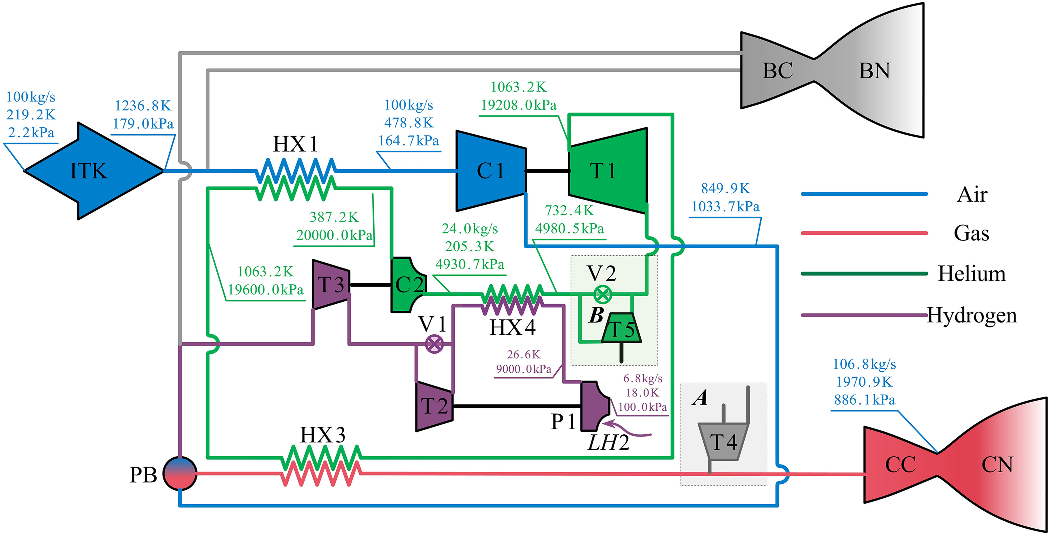
The thermodynamic configuration of an aspirated moderately precooled hypersonic engine coupled with power output is shown in Figure 1. Using liquid hydrogen as the fuel and cold source, it consists of a precooled turbine path, a bypass ram path and a fuel path.
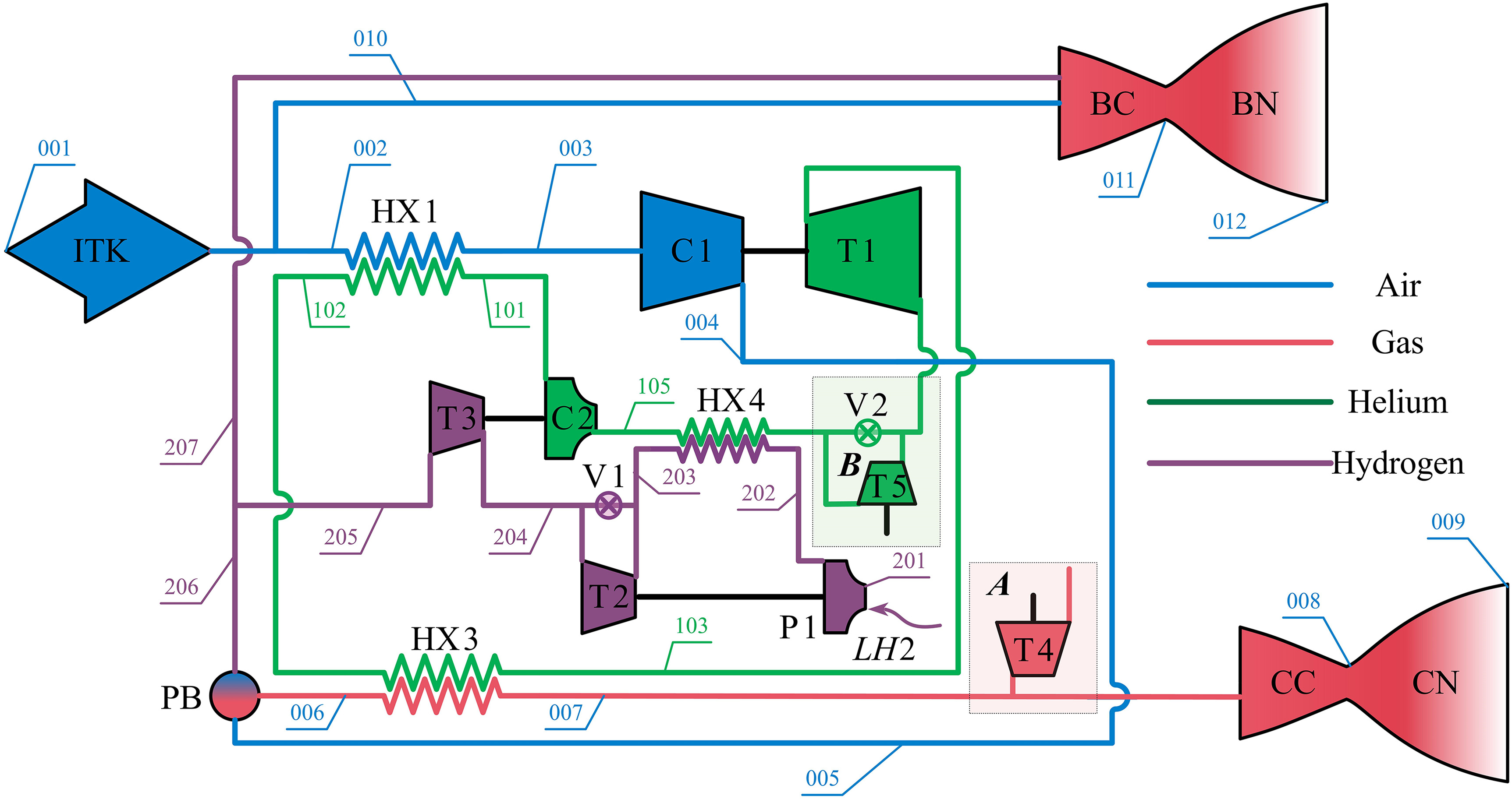
In the propulsion part, when the engine is operating at high Ma, the airflow first flows into the core path of the engine after decelerating and expanding in the intake ITK, then it is cooled down in the precooler HX1 and flows into the air compressor C1 to be pressurized. The pressurized air flows into the pre-burner PB and the main combustion chamber CC to be mixed and ignited with the fuel. Finally, the gas expands and accelerates in the nozzle CN to generate thrust. In the closed-cycle system, supercritical helium absorbs heat successively in HX1 and the high-temperature heat exchanger HX3. Then the helium expands in the main turbine T1 to drive C1 and discharges additional heat in the hydrogen-helium cooler HX4. Finally, the low-temperature supercritical helium is pressurized in the circulation pump C2 to restore the initial pressure. As for the hydrogen supply system, liquid hydrogen is pumped by the fuel pump P1 to HX4 to absorb heat. The hot gaseous hydrogen expands in the turbine T2 and turbine T3 to drive P1 and C2 respectively. Finally, the hydrogen flows into the PB to be ignited to produce high temperature gas. During the non-design operation, ITK may capture more air than the demand of the core engine. The remaining air is spilt into the bypass path, mixed and ignited with fuel in the bypass combustion chamber BC, and finally the gas expands and accelerates in the bypass nozzle BN to increase the engine thrust.
As for the power extraction, two different schemes were proposed. One is that extracted power is produced by high-pressure bleeding gas (Node A in Figure 1). In this scheme, the branch of high-pressure gas exiting the PB drives the power extraction turbine T4, and the generated power is output through the shaft. However, the gas after the expansion is discharged directly. The other is based on an additional branch downstream of the main helium turbine T1. The power output is generated by the helium turbine T5 (Node B in Figure 1). The expanding helium in the branch flows back to the main closed-cycle path through a manifold valve, where the pressures of two fluid are kept identical. Considering the difference between the two power extraction methods, a comparison of the two power extraction schemes will be illustrated later in this paper.
Based on the above working principle, a modular thermodynamic parameter calculation model is built, in which the following assumptions are adopted:
The modular thermodynamic process model for moderately precooled engines will be described in detail in the subsequent sections.Thermodynamic process calculation model
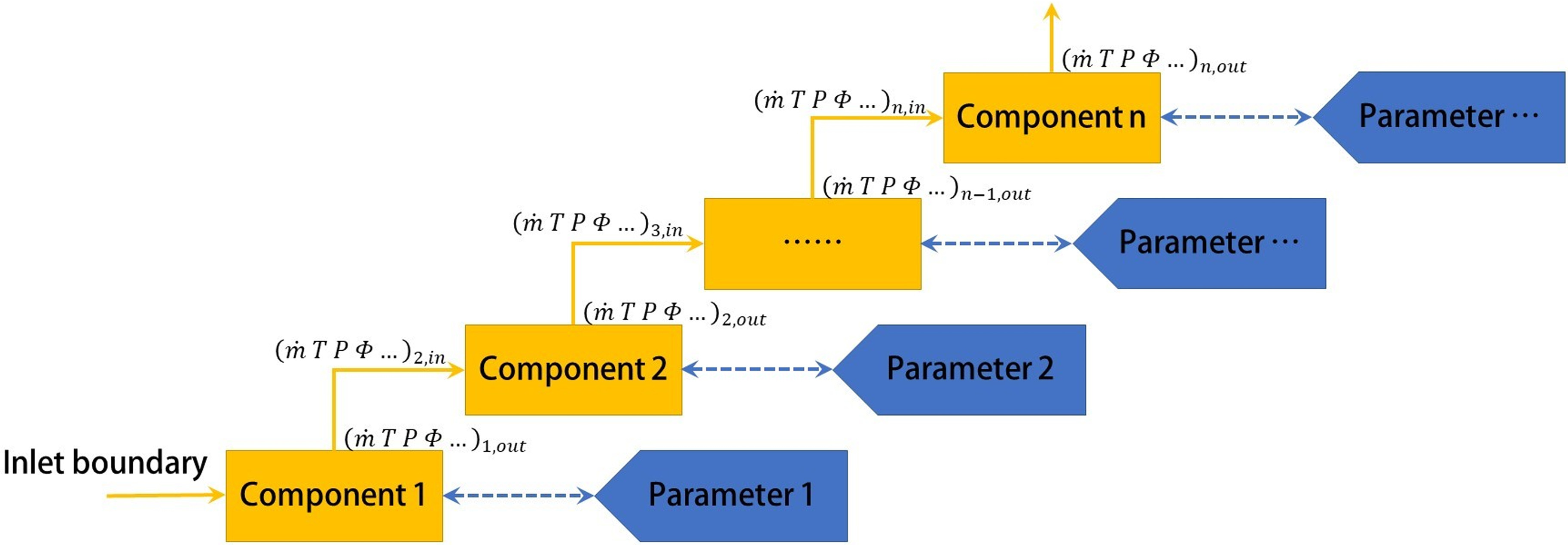
The “modular method” (shown in Figure 2) refers that the encapsulation of the thermodynamic calculation of each component model is confined in its own subroutine, which avoids the interference among the calculation of the respective thermodynamic processes. The interaction of parameters between the component and external is limited to the inlet thermodynamic parameters, outlet thermodynamic parameters and component performance parameters. Different types of precooled engine thermodynamic cycle configurations are essentially a combination of several common components while the number, type and work fluid of the components in each cycle are different. Therefore, the modular method can achieve fast and flexible modeling in the thermodynamic cycle analysis of different configurations, which simplifies the modeling of thermodynamic cycle. Moreover, the detailed modelling method used in this paper could be found in Zou et al. (2022) and it would not be given again in this paper.
Verification of thermodynamic cycle model
The performance data of SABRE-3 published is introduced to verify the accuracy of the component modeling and thermodynamic cycle modeling methods. Table 1 shows the comparison of the calculated results of specific impulse of SABRE-3 with the data in the Victor and Guillermo (2010), Victor (2013) and Longstaff and Bond (2011). In general, the deviation of the specific impulse in the range of Ma 0.0–5.0 is within 3.6% in turbine path, which ensures a credible calculation accuracy. In addition, the deviation of the calculated specific impulse in the whole engine is +1.6% and −4.3% for Ma 0.0 and Ma 5.0 flight conditions respectively. The component models also exhibit high accuracy, and Table 2 compares the calculated results with the data reported in the Victor and Guillermo (2010) for typical components at 0 and 25 km conditions. Additionally, according to Balepin (2007), the pre-cooler outlet temperature and equivalence ratio at the design point are reported as 140 K and 2.8, respectively. In this study, the calculated values are 125 K and 2.8, respectively. Therefore, the component and thermodynamic cycle modeling methods can meet the performance analysis requirements.
Table 1.
Modelling method validation based on SABRE-3 thermodynamic cycle (specific impulse).
Table 2.
The verification of typical component models.
Results and discussion
Analysis of moderate precooled engine thermodynamic cycle configuration
Parameter sensitivity
The moderate precooled engine cycle model established covers many components and design parameters. In order to improve the thermodynamic performance of the cycle to adapt to different missions, sensitivity analysis of some design parameters was carried out in this section to determine the critical parameters that have a greater impact on the essential performance of the engine.
The SOBOL method was introduced to conduct a study of influence of each design parameter. Based on the thermodynamic cycle configuration, 22 parameters were selected as the objectives of parameter sensitivity, which included the cycle thermodynamic design parameters and the performance parameters of each component. The number of random samples was 1,000 (22,500 cases totally). The study range of each parameter is shown in Table 3. In addition, the hydrogen-air mass ratio of 0.05832, i.e., the equivalent ratio was taken as 2.0.
Table 3.
Types and ranges of sensitivity analysis parameters.
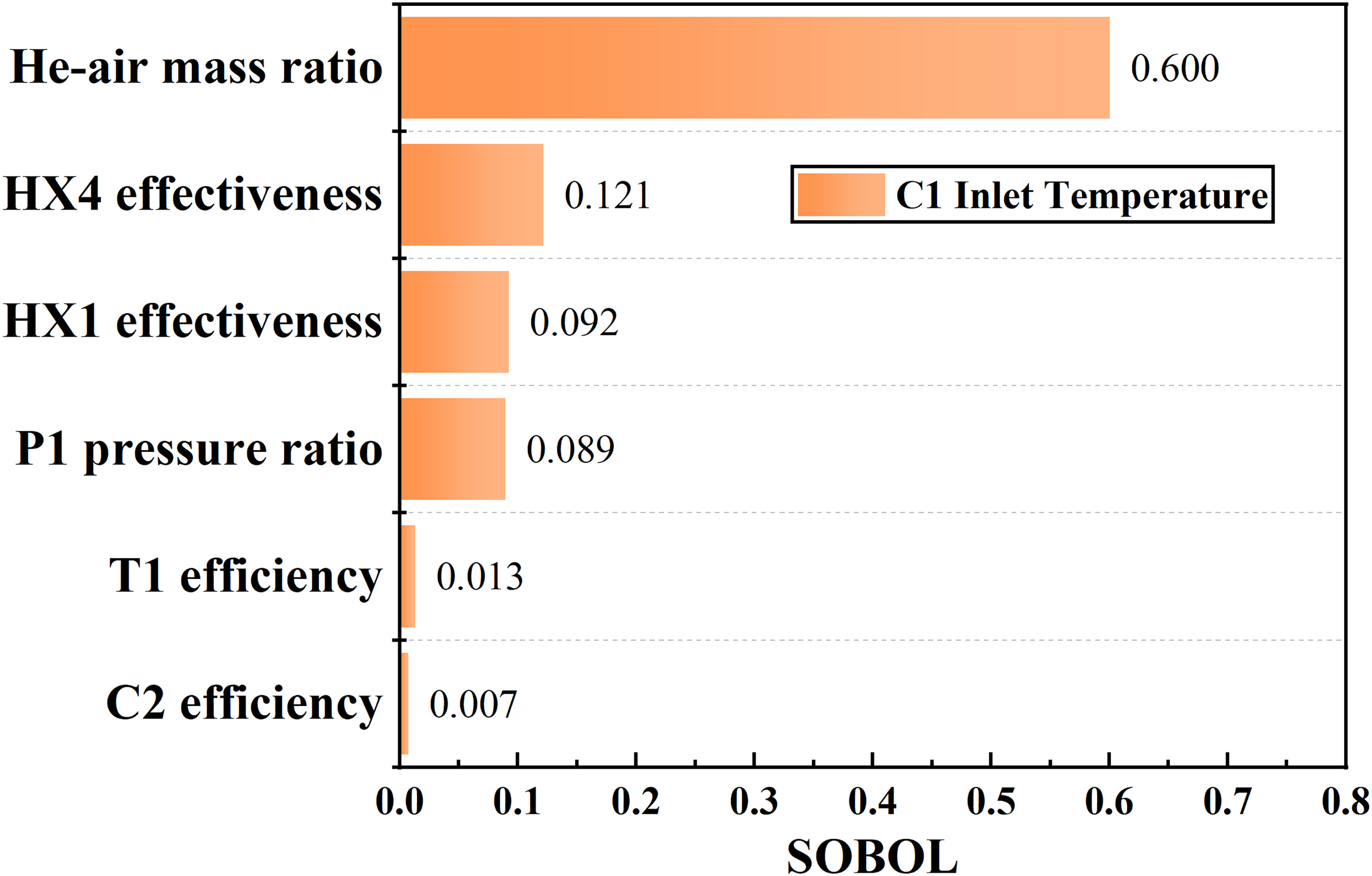
The inlet temperature of C1 deeply reflects the pre-cooling capability of the supercritical closed-cycle, so it is one of the targets of consideration. Figure 3 shows the results of the sensitivity analysis of the factors affecting the inlet temperature of C1. It is obvious that the helium-to-air mass flow ratio HAR has the greatest effect under a constant hydrogen-air equivalent ratio. This is because supercritical helium plays a heat transmittal and transformation role inside the closed-cycle system. The heat capacity matching relationship among hydrogen, helium and air determines the capacity to absorb heat in HX1 and the ability to discharge waste heat in HX4. In addition, the effectiveness of HX3, effectiveness of HX1 and pressure ratio of P1 have relatively significant effects on C1 inlet temperature. The pressure ratio of P1 mainly affects the inlet temperature of the hydrogen side of HX4. The variation of pressure ratio of P1 is more likely to lead to a larger variation of the inlet temperature of the hydrogen side because of its low temperature (blow to 50 K). The effectiveness of HX4 and HX1 directly affects the temperature of the supercritical helium flowing into HX1 and the heat transfer capacity of HX1. It is worth noting that HX1 has a more obvious effect on the inlet temperature of C1. Therefore, the above parameters should be the focuses of the optimization analysis of this thermodynamic cycle.
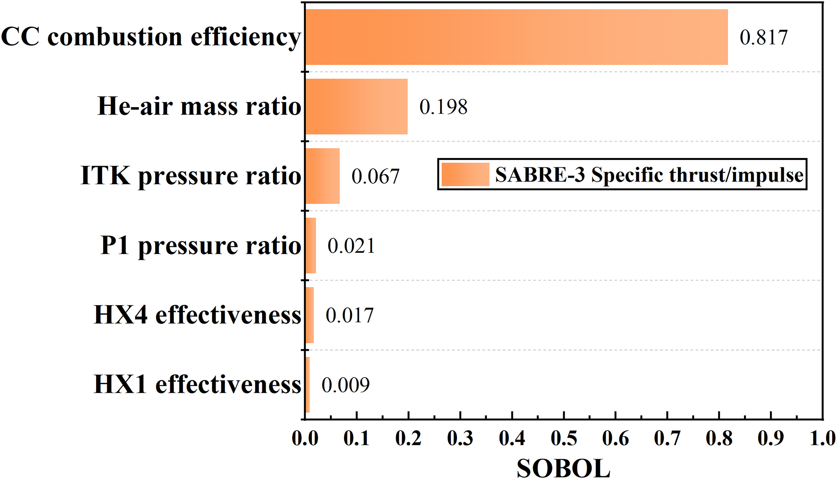
The sensitivity analysis results of engine specific thrust and specific impulse are shown in Figure 4. Due to the specified hydrogen-air equivalent ratio, the results for specific thrust and specific impulse are the same variation. Firstly, the combustion efficiency of CC is the component performance parameter with the greatest effect on the propulsion performance. It monotonically affects the outlet temperature of CC, indirectly affecting the exhaust velocity that has the greatest impact on the propulsion performance. Therefore, it is necessary to fully consider the impact of combustion chamber performance especially the combustion efficiency in the component design process. Secondly, HAR has a large impact on the heat-to-mechanical work conversion and pre-cooling capability of the closed-cycle system, which indirectly affects the engine thrust performance. In addition, the total pressure recovery coefficient of ITK affects the exhaust pressure more markedly when varying in the range of [0.1,0.2], making the maximum variation range of nozzle exhaust pressure up to 2 times. This causes a large variation on the propulsion performance. So the performance optimization analysis of ITK should be also focused on during the design of components.
Due to the strong coupling of multiple parameters on the overall performance, the parameter combinations for optimal performance would not be obtained by direct parametric analysis. Therefore, the subsequent study took the above sensitivity analysis results as reference, and these parameters were specified reasonable values based on the existing component levels. The final performance of the whole engine and the main thermodynamic parameters are shown in Table 4.
Table 4.
The parameters of moderate precooled thermodynamic cycle benchmark scheme.
Parametric analysis of power extraction
Influence of power extraction parameters
The two power extraction schemes mentioned operate on different flow paths and their working fluids are different. Therefore, the impact of the two schemes on engine performance is noteworthy when meeting the same power requirements of vehicle systems. This benefits to select the appropriate power extraction scheme for different flight missions.
According to the working principles of the two different power extraction methods in Figure 1, the design parameters of each method are summarized as shown in Table 5.
Table 5.
The design parameters for power extraction.
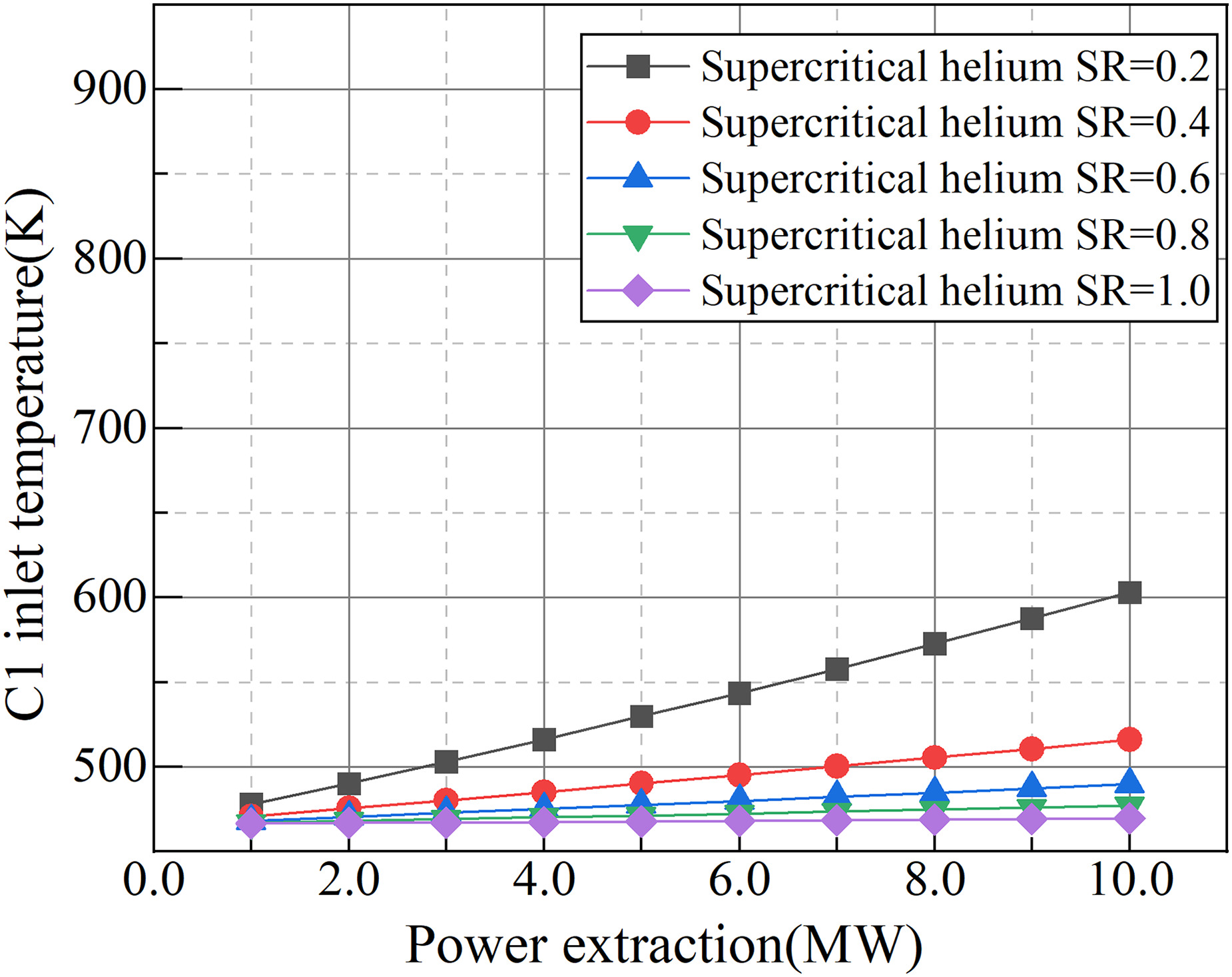
The effect of power extraction on the performance of C1 was investigated in this subsection. Since the gas is directly extracted after the air compressor in the first method, it cannot affect C1 in the design point, so the analysis was conducted only for the second method, i.e., extracting power from closed-cycle system. Figure 5 shows the variation of the inlet temperature of C1 under 150 kg/s air flow rate. As shown in the curves in Figure 5, the C1 inlet temperature increases slowly as the extracted target power increases. This is due to the fact that the additional power extraction reduces the ability of the closed-cycle system to deliver power through the C1-T1 axis, which leads to the drop of the hydrogen flow path outlet pressure. Meanwhile, the pressure drop in the hydrogen flow path enhances the ability of T3 to expand and deliver power, resulting in an increase of pressure ratio and the outlet temperature of C2, which leads to a small increase in C1 inlet temperature. In addition, with the decrease of the split ratio, the flow pressure loss increases in the non-working branch unconnected to T5, resulting that more high-temperature helium flows into HX4 without expanding to be cooled down. So the inlet temperature of the helium side of HX1 increases significantly, weakening the pre-cooling capability of the closed-cycle system. For example, in the case of split ratio 0.6, when the extracted power increases from 1 to 10 MW, the C1 inlet temperature would increase from 468.3 to 489.7 K.
The variation of the pressure ratio of C1 is opposite to its inlet temperature variation as shown in Figure 6. With the increase of extraction power, C1 pressure ratio monotonically decreases. Because of the additional pressure loss caused by the non-working branch in the split process, the flow loss is more serious in the case of lower split ratio, which could cause a more significant decrease of C1 pressure ratio.
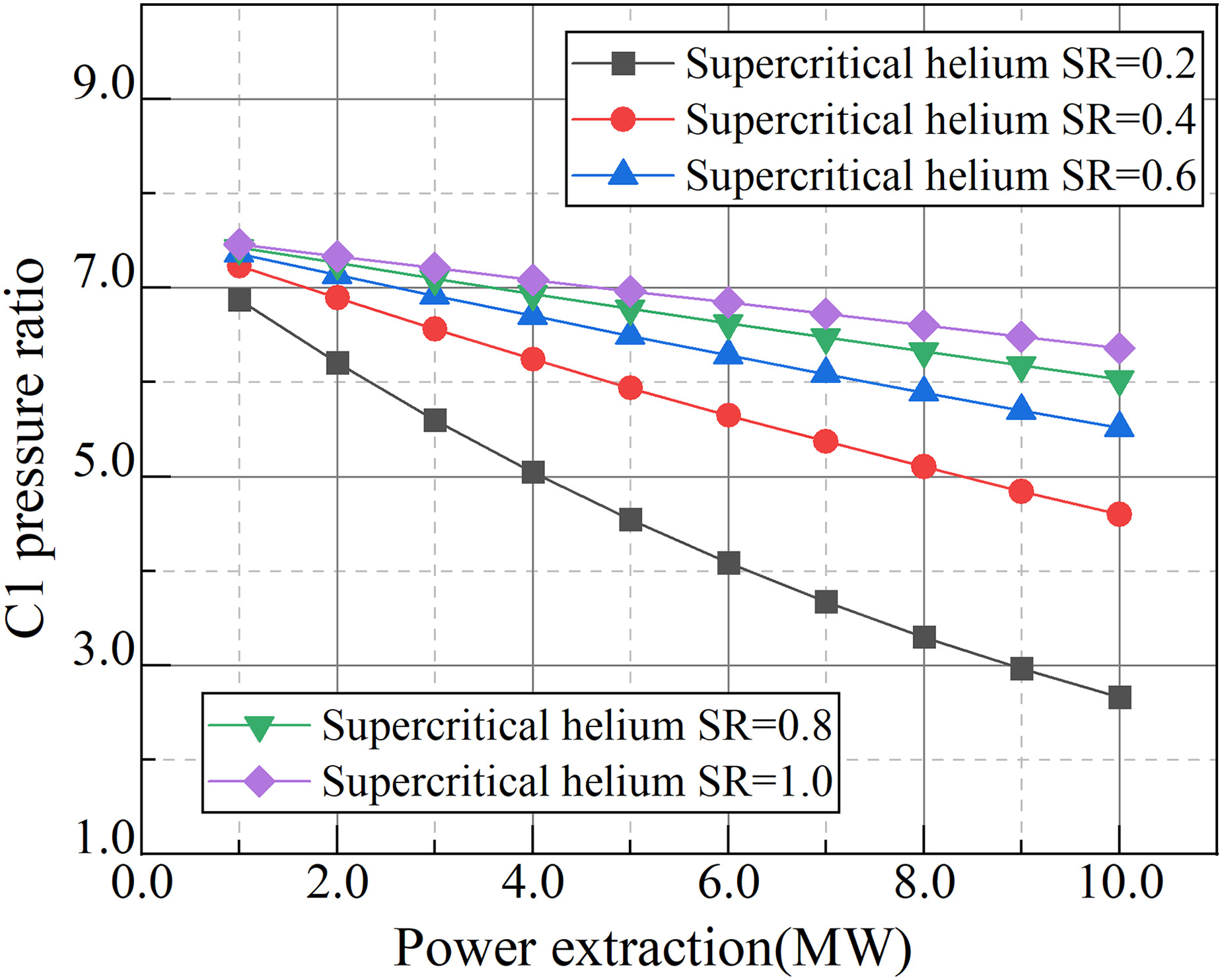
According to the above analysis, it is obvious that there is a significant pressure loss in the non-working branch which reduces the pre-cooling ability and heat-to-work conversion performance. So the flow rate of the non-working branch should be reduced as much as possible while the power extracted demand was satisfied.
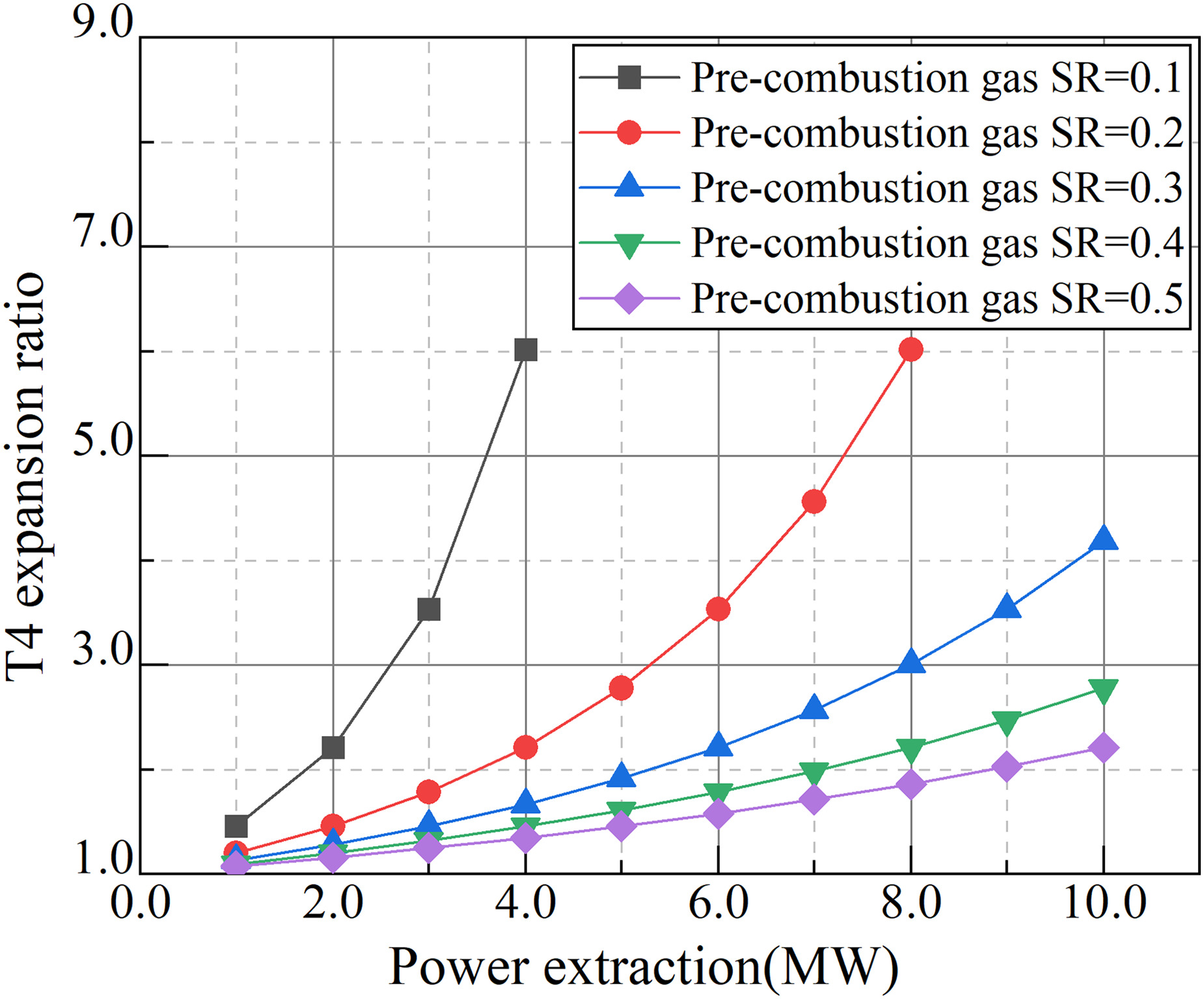
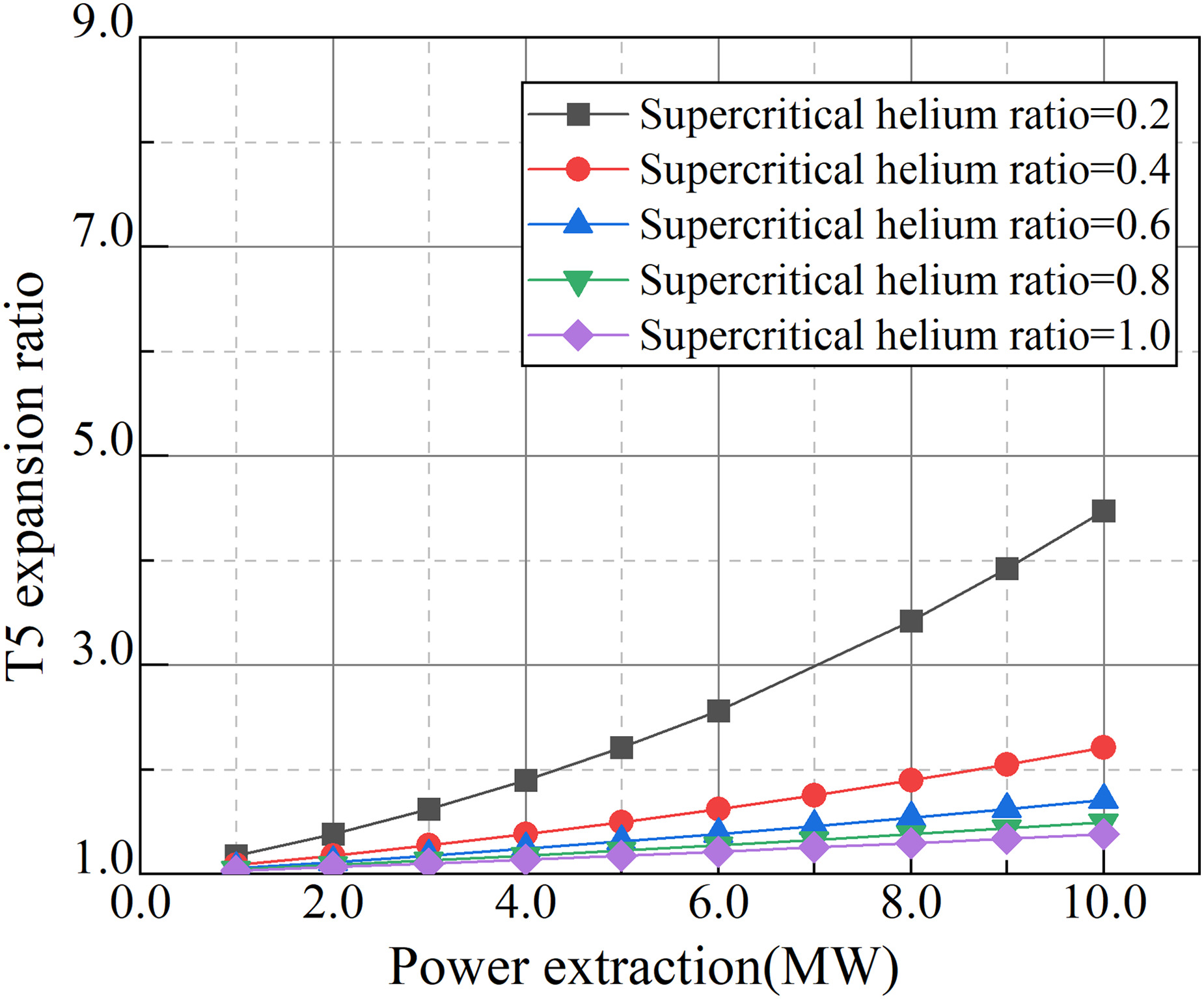
Figures 7 and 8 show the respective expansion ratios of the gas turbine and helium turbine for the two power extraction methods at 150 kg/s design flow rate. As seen, the expansion ratios of T4 and T5 appear a non-linear increase with the increase of power extraction, and the variation of the expansion ratio of T4 is more obvious because the specific heat of helium is greater than that of combustion gas. The expansion ratios of T4 and T5 increase respectively from 1.1 to 2.8 and 2.2, when the split ratios are both taken as 0.4 and the extracted power is increased from 1 to 10 MW.
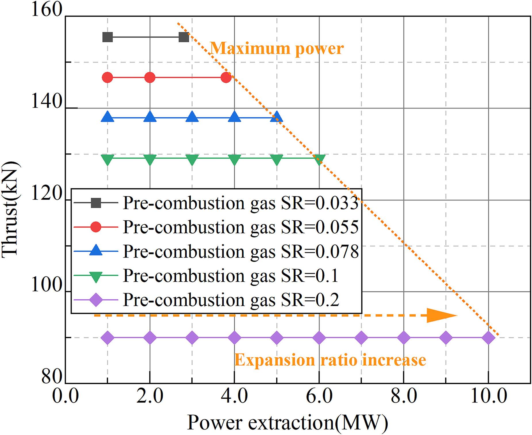
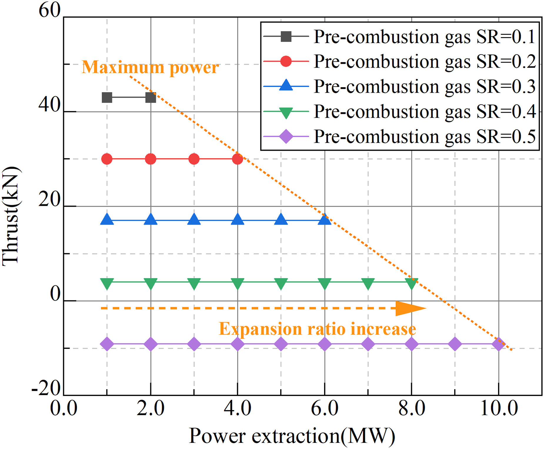
Figures 9 and 10 show the effect of the first method for power extraction on the engine thrust performance. Taking the design air flow rate of 150 kg/s as an example, with the increase of the extracted power, the thrust and specific impulse decrease significantly. According to Figure 9, when the extracted power increases from 1 to 8 MW, the engine thrust decreases from 170.8 to 90.0 kN. By comparing Figure 9 with Figure 10, it is suggested that the engine could only maintain a high propulsion performance in the cases of larger design thrust magnitude.
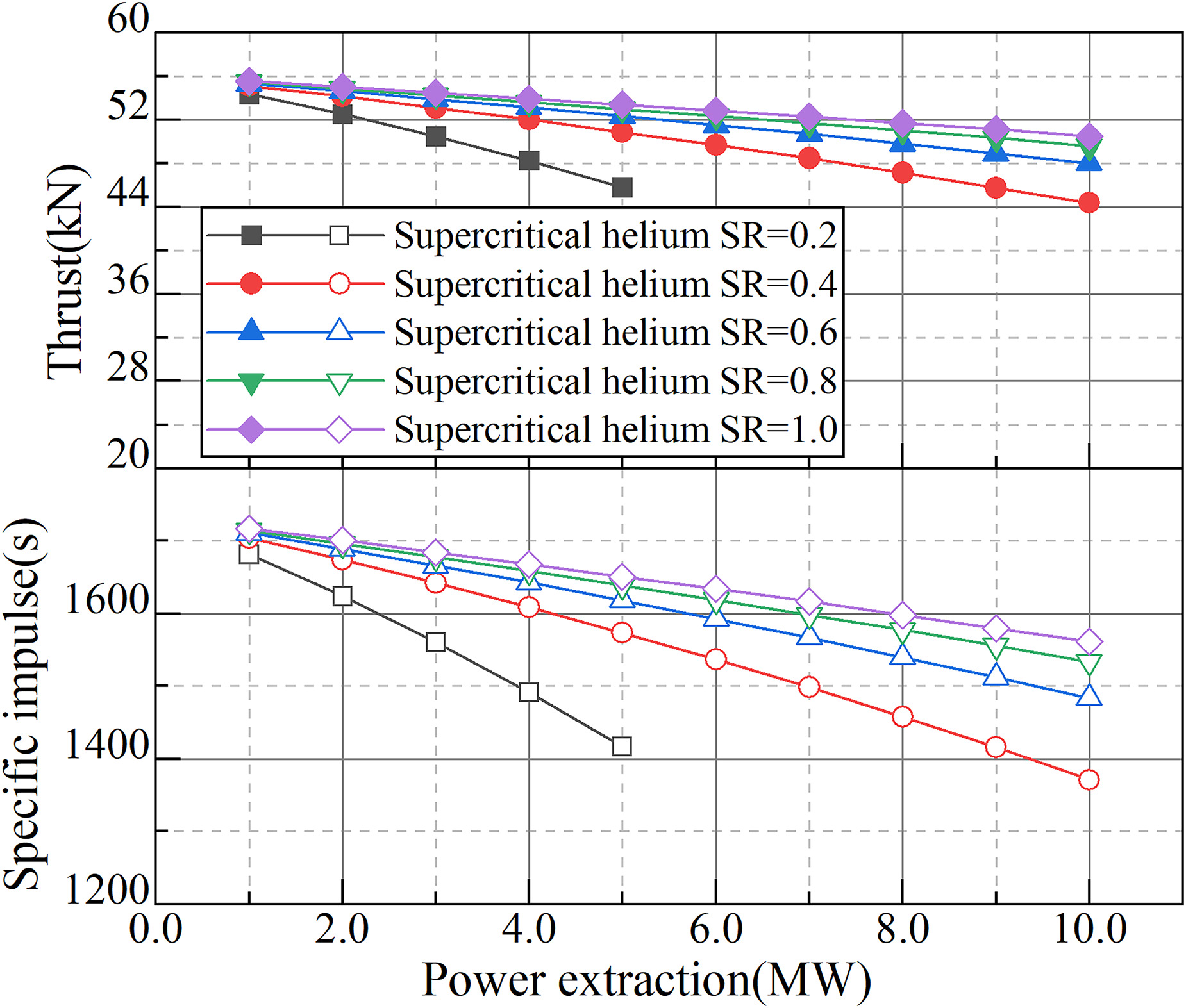
As shown in Figure 11, for the second method for power extraction, the better thrust and specific impulse characteristics are maintained. Under the air design flow rate of 50 kg/s, the maximum thrust and specific impulse decrease respectively from 55.5 kN and 1,717 s to 50.5 kN and 1,562 s when the extracted power is increased from 1 to 8 MW, with a decrease of only 9.0%. It is obvious that the method for power extraction by closed-cycle system with a split branch has less effect on propulsion performance in Ma 5 flight. And according to its operation principle, it can be combined with other aircraft heat management and utilization requirements to achieve more efficient heat-to-power conversion, which is a more potential approach for power extraction from precooled engine.
Based on the power extraction method of the closed-cycle with a split branch, a moderate precooled engine thermodynamic cycle scheme was proposed with coupled power extraction as the target of 2 MW, in which the thermodynamic parameters are shown in Figure 12. The scheme achieved a performance level of 109.6 kN thrust and 1,645 s specific impulse with 2 MW power extraction at 25.8 km cruise altitude and Ma5.0 cruse speed, which lost just 2.8% propulsion performance compared with the normal propulsion scheme without power extraction. This scheme can provide a new idea for electrical energy generation and utilization on hypersonic vehicles.
Conclusions
In this paper, a coupled power extraction moderate precooled cycle engine scheme based on supercritical helium closed cycle was established, and the overall performance of the scheme at design point was calculated and analyzed. The main conclusions obtained are as follows:
For a standard moderate precooled engine thermodynamic cycle, in terms of the sensitivity of key parameters affecting its overall performance, the heat capacity matching relationship between hydrogen and air has the greatest effect on the air compressor inlet temperature and pressure ratio, which is much higher than other factors. Meanwhile, the combustion efficiency of the main combustion chamber has largest impact on the propulsion performance (specific thrust and specific impulse) with a specified hydrogen equivalent ratio while the helium-air heat capacity flow ratio has a relatively significant effect.
Although the power extraction method using pre-combustion gas extracted has less impact on the air compressor operating state at design point, the engine propulsion performance is affected seriously. By contrast, the power extraction method using closed-cycle with a split branch affects the air compressor operating state, but the propulsion performance decreases less, and it can be combined with other aircraft heat management and utilization requirements to achieve more efficient heat-to-work conversion. So the second method can be a more appropriate scheme.
A moderate precooled engine thermodynamic cycle scheme with power extraction as the target is proposed, achieving 109.6 kN thrust and 1,645 s specific impulse with 2 MW power extraction at 25.8 km cruise altitude and Ma5.0 cruise speed, and only 2.8% propulsion performance loss compared with the standard scheme without power extraction, which can provide a new approach of electrical energy generation and utilization for horizontal takeoff and landing, reusable hypersonic vehicles.
Nomenclature
Acronyms
BN
Bypass nozzle
C1
Air compressor
C2
Circulation pump
CC
Main combustion chamber
CN
Nozzle
DE
Design point
HAR
Helium-to-air mass flow ratio
HX1
Precooler
HX3
High-temperature heat exchanger
HX4
Hydrogen-helium cooler
ITK
Intake
Ma
Mach number
P1
Fuel pump
PB
Pre-burner
SR
Spilt ratio
T1
Main turbine
T2
Turbine 2
T3
Turbine 3
T4
Power extraction turbine
T5
Helium turbine