
Introduction
A potential for increasing the efficiency of steam and gas turbines is the further development of sealing technologies in order to reduce parasitic losses in the blade path. One of these concepts is the brush seal, which has demonstrated an improved leakage performance against conventional sealing technologies, resulting in a potential increase of overall efficiency of more than 1% and is therefore increasingly used in today's turbomachines (Pastrana et al., 2001). Compared to conventional labyrinth seals, the compliant brush seal has proven significant performance benefits (Ferguson, 1988), achieving leakage reductions of up to 80% compared to labyrinth seals (Dinc et al., 2002). Concurrently, brush seals have an enhanced capability to accommodate shaft excursions and require less axial space due to their increased pressure load capability per stage (Chupp et al., 2006). Furthermore brush seals have a positive effect on the dynamic stability of turbomachines due to their swirl breaking capability (Helm et al., 2008).
The general design of a brush seal includes a bristle pack located between a frontplate and a supporting ring (backplate). Both clamped and welded designs are commercially available as shown in Figure 1. The influence of different design parameters such as the bristle diameter d, the fence height cfh, the radial clearance cg, the width of the of the bristle pack B or the free radial bristle length lr on the operating performance of brush seals are widely investigated (Basu et al., 1994; Crudgington, 1998; Berard and Short, 1999). For the clamped design, Schwarz et al. (2014) identified the axial inclination φ of the bristle pack, described by the angle between the direction of the bristle pack and the direction perpendicular to the shaft, as another significant parameter on the seals performance. Three different groups of axial inclinations were identified, classifying low, medium and high inclined brush seals.
Brush seals with low inclinations φ < 0.5° show high blow down capabilities. In combination with the compression of the bristle pack for increasing pressure differences, low inclined seals show a superior leakage performance at high pressure differences. However, seals with a low inclination are prone to bristle oscillations at lower pressure differences. These undesired instabilities of the bristle pack lead to an increased leakage mass flow and wear of the bristles and their counter surface.
The bristle pack of high inclined seals with inclinations φ > 5° shows a pre-compression of the bristle pack, which results in increased friction between the individual bristles and between the bristle pack and the backplate. Therewith, higher damping is present, leading to a reduced or completely suppressed of bristle oscillation.
Compared to seals with a low inclination, high inclined seals feature lower leakages, but show an increased radial stiffness at low pressure ratios. Hence, low inclined seals are beneficial at high pressure differences in terms of improved leakage performance and low radial stiffness at higher pressure differences. Due to the negative influence of an increased radial stiffness on the wear behaviour and heat input caused by rubbing, a lower stiffness of the bristle pack is desired.
Medium inclined seals offer a mix of the properties of both types of seals and were found suitable for moderate pressure differences up to 10 bar (Schwarz et al., 2014).
Since the operation of conventional powerplants involves more frequent power changes and part load operation due to the increased amount of intermittent renewable energies, all seals of the turbine have to adapt to varying loads and a more flexible operation (Brouwer et al., 2015). Contrary to the conventional layouts of brush seal parameters, optimized for one specific design point, an adaptation with regard to a wider operating range is required for modern power conversion. Since low and high inclined seals are more suitable for either elevated or lower pressure differences, the aim is to combine the advantages of both types of seals while avoiding their undesired properties.
Experimental setup
For the investigations presented in this paper experiments on two different test rigs were conducted. For preliminary investigations of the novel seal a test rig operated with compressed air and without rotating shaft was used. Second, the new seals operating performance is analysed under realistic steam conditions at TU Braunschweig's hot steam test rig. A detailed description of the test rigs is given in (Büscher, 2010; Raben et al., 2013, 2017, pp. 3–6; Schwarz et al., 2014).
Cold-air test rig
The air test rig is used for the characterization of brush seals with respect to the blow down capability, the axial behaviour and the radial stiffness of the seals bristle pack at pressure differences of up to 8 bar. For each investigation, 24 reproducible circumferential positions can be examined. The investigations are conducted using up to three different non-rotating disks with a diameter equivalent to the shafts diameter of the hot steam test rig, as described in detail in (Schwarz et al., 2012, 2014). As depicted in Figure 2, an optical access allows the evaluations of the blow down and the axial behaviour. The visual observations provide additional information about bristle oscillations under pressurization and wear of the bristle pack. Furthermore, the mass flow as well as the pressures and temperatures upstream and downstream of the seal are acquired during all measurements. The systematic uncertainty for the pressure measurements is given in Table 1. For the leakage measurement an uncertainty of ±1.06% was determined (Schwarz, 2018) while all optical measurements have an uncertainty of ±0.02 mm.
Table 1.
Uncertainty of pressure measurements at the cold-air test rig (Schwarz, 2018).
| Δp | Systematic uncertainty |
|---|---|
| 1 bar | ±2.24% |
| 2 bar | ±1.12% |
| 3 bar | ±0.75% |
| 4 bar | ±0.56% |
Hot steam test rig
The hot steam test rig of the TU Braunschweig was erected in the 1990's and is located in a local power plant in Braunschweig. It allows the investigation of the operational performance of radially adaptive seals such as single or multistage brush seals. Both long-term and short-term investigations under conditions relevant for steam turbines are feasible. A sectional view of the test rig is depicted in Figure 3. The central element is the high-pressure (HP) chamber. Due to its double flow arrangement, two seal configurations can be applied. Based on their installation position, the seals are labelled as displacement (DS) and motor side (MS) seals. The hot steam is fed in the center of the HP-chamber and is returned to the low-pressure system of the power plant after flowing through the seals. The steam parameters are limited to a maximum of approx. 500°C and the maximum inlet pressure of 50 bar. Driven by an 80 kW electric motor the shaft is operated at a nominal speed of 10,000 rpm resulting in a maximum surface speed of nearly 160 m/s. The shaft is instrumented with thermocouples in order to analyse the temperature distribution below the seals. The casing of the HP-chamber is supported by two struts which can be heated and cooled with the purpose of varying the casing position relative to the shaft in order to achieve eccentricities of the shaft up to 0.5 mm. Measurement uncertainties for the data acquired at the test rig are summarized in Tables 2 and 3.
Table 2.
Uncertainty of pressure and temperature measurements at the hot steam test rig (Büscher, 2010; Raben et al., 2017, p. 6).
| Parameter | Systematic uncertainty |
|---|---|
| Pressure (50% full scale) | ±0.6% |
| Temperature (450°C) | ±0.8% |
| Temperature instrumented shaft | ±0.6% |
Table 3.
Uncertainty of mass flow measurements at the hot steam test rig (Büscher, 2010).
| Systematic uncertainty | |
|---|---|
| 270 g/s | ±1.0% |
| 170 g/s | ±1.1% |
| 100 g/s | ±0.98% |
| 50 g/s | ±0.98% |
The novel seal design
In order to allow for a wide operating range, a novel seal design with pressure-actuated backplate based on the idea of Schwarz and Friedrichs (2015) was designed, targeting on the utilization of the positive operating properties of both the low and high inclined seals. The further development of Schwarz's concept into a testable configuration is presented.
The key component of the adapted seal, which is shown in Figure 4, is the axially deflecting backplate in combination with a low inclined bristle pack. Under no or low pressurization, the backplate is pushed in the upstream direction by springs so that the bristles are compressed axially and the bristle pack becomes similar to a high inclined brush seal. With increasing pressure difference, the deflectable backplate moves downstream until the backplates axial position is equivalent to the geometry of a conventional backplate. Consequently, the formerly pre-compressed bristle pack is released, and the seals properties equal the low inclined brush seal.

Preliminary investigations
The spring rate for the investigations under air was chosen to allow for a full axial deflection of the backplate at at pressure difference of Δp = 3.1 bar, as shown in Figure 4. The value complies with the mean value of the expected achievable pressure difference at the test rig used for the preliminary investigations. It was chosen to ensure the deflection of the actuated backplate within the achievable range of the pressure difference of the test rig. In the unpressurized state the distance between front and backplate is reduced by 0.4 mm compared to the standard design.
The behaviour of three bristle packs with differing axial inclinations and bristle diameters was evaluated for a standard and an axially deflecting backplate design up to a maximum pressure difference of 4 bar. For this purpose the three bristle packs BP1, BP2 and BP3 were successively investigated with the conventional and pressure-actuated backplate configuration. The investigations include the characterisation of bristle oscillations and the leakage mass flow through the seals. To determine the influence of the novel backplate on seal performance and the ability to suppress bristle oscillations, the results gained for both designs are compared.
The design parameters of the bristle packs are summarized in Table 4. All bristle packs are made of Haynes 25 alloy and have an inner diameter of 300 mm while their bristles have a lay angle of λ = 45° in combination with a free radial bristle length lr = 7.3 mm. Bristle pack BP1 has a medium axial inclination of φ = 3° while BP2 and BP3 are low inclined with an angle of φ = −2°. BP1 and BP2 have a bristle diameter d = 0.07 mm. The bristle pack of BP3 has a comparatively lower packing density due to a greater bristle diameter of 0.1 mm. According to prior investigations (Schwarz et al., 2014), the chosen brush designs are prone to bristle oscillations for low pressure differences, making them suitable for the investigations shown here.
Investigations under hot steam conditions
Based on the results of the preliminary investigations, a further design was developed for the application in the hot steam test rig. The target of the investigation under steam is to demonstrate the functionality under realistic operating conditions. The spring rate was adjusted to allow for a full deflection of the backplate at a pressure difference of Δp = 12 bar. At this pressure level, it can be assumed that bristle oscillations no longer occur (Schwarz et al., 2014). It can also be expected that the described loosening of the bristles does not occur after the backplate movement has ended, as the bristle pack is already sufficiently compressed due to the high pressure difference. In contrast to the design of the preliminary investigations, the distance between the front and backplate is reduced by 0.6 mm in the unpressurized state compared to the conventional design.
For the investigation of the new design, two tests, referred to as BST18 and BST19a were conducted. For BST18 the new seal design with deflectable backplate was investigated along with a second brush seal with a high inclined bristle pack. The new seal design is named PABS (pressure-actuated brush seal), and the brush seal installed upstream MS1 (motor side 1). The double flow design of the test rig requires the integration of a second seal configuration. For this purpose the identically designed seals DS1 (displacement side 1) and DS2 (displacement side 2) were installed on the displacement side, whereby the numbering corresponds to the sequence of installation in the direction of flow. An overview of the seals parameters is given in Table 5. All seals have a lay angle λ = 45° and bristles made of Haynes 25.
Table 5.
Parameters of the brush seals investigated in BST18.
The bristle pack of the novel seal with pressure-actuated backplate has an averaged axial inclination φ = −0.5° when not compressed by the backplate. The bristle pack of PABS was split in two partial rings by the manufacturer, resulting in slightly differing values for the averaged axial inclination φ for both rings. Consequently the lower partial ring (90°–270° in rotational direction) has an axial inclination φ = 0°, while the upper partial ring (270°–90° in rotational direction) has an inclination φ = −1°. MS1 was used as a backup for PABS and was designed with thicker bristles and a radial gap cg = 0.1 mm and a fence height cfh = 0.9 mm, with the purpose to create a comparatively weak seal to allow PABS to carry most of the pressure load. The displacement side seals differ from the type of seals of the motor side. These seals are welded and not clamped and do not comprise an axial inclination. Their bristle diameter is d = 0.127 mm and the free radial bristle length amounts to lr = 11.9 mm. The seals were assembled into the seal carrier so that the downstream seal PABS was positioned above thermocouples integrated in the shafts body, see Figure 5.

The BST18 testing programme covered a total of 22 days, including pressure variations ranging from 2 bar to 50 bar and shaft speed variations between 2,000 rpm and 10,000 rpm. Furthermore, eccentricity tests with eccentricities of 0.3 mm and 0.5 mm were conducted. The details of the testing parameters during the eccentricity runs are presented in Table 6. The parameter ex represents the value by which the seal was elevated to simulate an eccentricity of the shaft while n is the shaft speed and pHP the pressure of the HP-chamber during the tests.
Table 6.
Parameters during the eccentricity tests of BST18.
| test no. | ex | n | pHP |
|---|---|---|---|
| Ex1 | 0.3 mm | 1,000 rpm | 7.5 bar |
| Ex2 | 0.3 mm | 10,000 rpm | 30.0 bar |
| Ex3 | 0.5 mm | 10,000 rpm | 15.0 bar |
During the second test, BST19a, the setup for the motor side was identically chosen to BST18 with the exception that the pressure-actuated backplate of PABS was fixed in the position corresponding to the unpressurized state. The aim is to determine differences in the measurement data regarding the seal PABS in order to make reliable conclusions about the movement of the pressure-actuated backplate during operation. For this purpose the pressure and speed variations of BST18 were repeated in BST19a during a testing program covering 8 days. Since the comparison between BST18 and BST19a for PABS is in focus, the remaining setup or measurement data of the second hot steam test will not be discussed further.
For improved comparability of the seals with each other and with the results of other test rigs, the leakage mass flow is characterized by the calculated effective clearance, defined as (Crudgington, 1998; Gaszner et al., 2013)
The values for
Results and discussion
Preliminary investigations at the cold-air test rig
The bars in Figure 6 indicate the actual movement of the pressure-actuated backplate, measured through the optical access of the test rig. The pressure level at which the movement of the backplate sets in differs for the three bristle packs. For BP2 the deflection of the backplate starts at a pressure difference of 0.8 bar and ends at 2.2 bar. For BP1 and BP3 the movement sets in at higher pressure differences of 1.4 and 1.2 bar and ends at 2.8 and 2.6 bar. Thus the backplate deflects at lower pressure differences as intended by the original design. It can be assumed that this behaviour is mainly influenced by a force on the backplate induced by the bristle pack itself. The force increases with increasing axial inclination and increasing stiffness due to the bristles diameter. Therefore the pressure level for complete axial deflection of the backplate lowers with increasing axial inclination of the bristle pack and increasing bristle diameter.
Figure 6.
Reduction of the oscillating bristle width and the leakage mass flow due to the pressure-actuated backplate during the preliminary investigations.

Due to manufacturing tolerances, the actual reduction of the distance between front- and backplate of the brush seal in unpressurized state had a value of 0.56 mm instead of the 0.4 mm of the intended design. Consequently the bristle packs were even more compressed than initially intended.
Figure 6 shows the reduction of the bristle oscillations and the leakage mass flow due to the application of the deflectable backplate compared to the conventional design. The values are averaged over the 24 circumferential measurement positions. It is shown that the oscillating part BOS of the bristle pack is noticeably reduced by the compression of the deflectable backplate. Compared to the design of a clamped brush seal without a deflectable backplate, the oscillations were reduced up to 92% for BP1. This is caused by the increased inter-bristle friction as well as between bristles and the backplate which, in turn, results from the increased compression of the bristle pack by the pushing backplate. An example for the compression of the bristle pack and the suppression of the oscillations is presented in Figure 7 for BP1 for a pressure difference Δp = 2 bar. It can clearly be seen that the bristle pack is compressed by the upstream position of the backplate which leads to a reduction of the bristle pack width B, to a total disappearance of the oscillations and therefore of the oscillating bristle width BOS.
Figure 7.
Axial behaviour of BP1 for the conventional (a) and the pressure-actuated backplate (b) at Δp = 2 bar.

Due to the significantly lower axial inclination the described effect is less pronounced for BP2 and BP3. The compression of the bristle pack also enhances its density which leads to a reduction of the leakage mass flow of 20–40% for all of the bristle packs compared to the design of a clamped brush seal without a deflectable backplate.
After deflection of the backplate, a significant increase of the leakage mass flow and the oscillations is present, which has to be attributed the movement of the backplate, reducing the pre-tension of the bristle pack, but not yet resulting in a new arrangement of the bristles.
Backplate deflection under hot steam conditions
Since the main objective of the hot steam tests were to investigate the novel seal design with pressure-actuated backplate, the findings on the functionality of the new seal will be discussed first. Representative examples for the behaviour of the seal PABS are given, which were repeatedly determined during the two steam tests. All of the discussed pressure variations were conducted at a shaft speed n = 10,000 rpm.
In a first step, a distinction is made between the opening and closing of the pressure-actuated backplate. The opening of the backplate with increasing pressure difference involves the axial deflection of the backplate in downstream direction, whereby the pre-compression of the bristle pack by the backplate is relieved. The closing describes the reversed movement of the backplate towards upstream direction during the decrease of the pressure difference. The evaluation and comparison of the measurement data of BST18 and BST19a revealed that the displacement of the backplate can be determined by the analysis of the effective clearance heff and the data of the thermocouples in the shafts surface below seal PABS.
Figure 8 shows the corresponding data for the pressure increase during a pressure variation for the tests BST18 and BST19a. Directly after increasing the pressure difference across PABS from 14 bar to18 bar and further from 18 bar to 23 bar a rise of the shaft temperature can be observed for the fixed backplate configuration during BST19a. This behaviour can be accounted to a pronounced blow down of the bristle pack causing increased rubbing of the bristle pack on the shafts surface and resulting in an increased heat generation. This rise in temperature can not be observed for the corresponding pressure rise during BST18. The explanation for this difference is that during BST18 the backplate was already deflected. Hence, the pre-compression of the bristle pack was relieved, making it less stiff in radial direction. Compared to the pre-compressed bristle pack of PABS during BST19a, the force on the rotor induced by the blow down is lower, leading to a decreased heat input into the shaft.
Figure 8.
Difference pressure, effective clearance and shaft temperatures for seal PABS during a pressure rise in BST18 and BST19a.
An indication for the closing of the backplate is presented in Figure 9, showing a pressure reduction during one of the pressure variations. For the effective clearance heff of PABS, an increase can be observed up to a pressure difference Δp = 5 bar for both backplate configurations, caused by the decreasing compression and blow down of the bristle pack. During the further reduction of the pressure difference, a decrease of the effective clearance can be observed in the data of BST18, while BST19a continuously shows a positive trend beyond this point. The decrease of the effective clearance indicates the beginning closing of the pressure-actuated backplate, resulting in a compression of the bristle pack. The consequently increased density of the bristle pack leads to a reduced leakage mass flow of the seal. Due to the fixed position of the backplate this effect can not be observed during BST19a.
Figure 9.
Difference pressure, effective clearance and shaft temperatures for seal PABS during a pressure reduction in BST18 and BST19a.
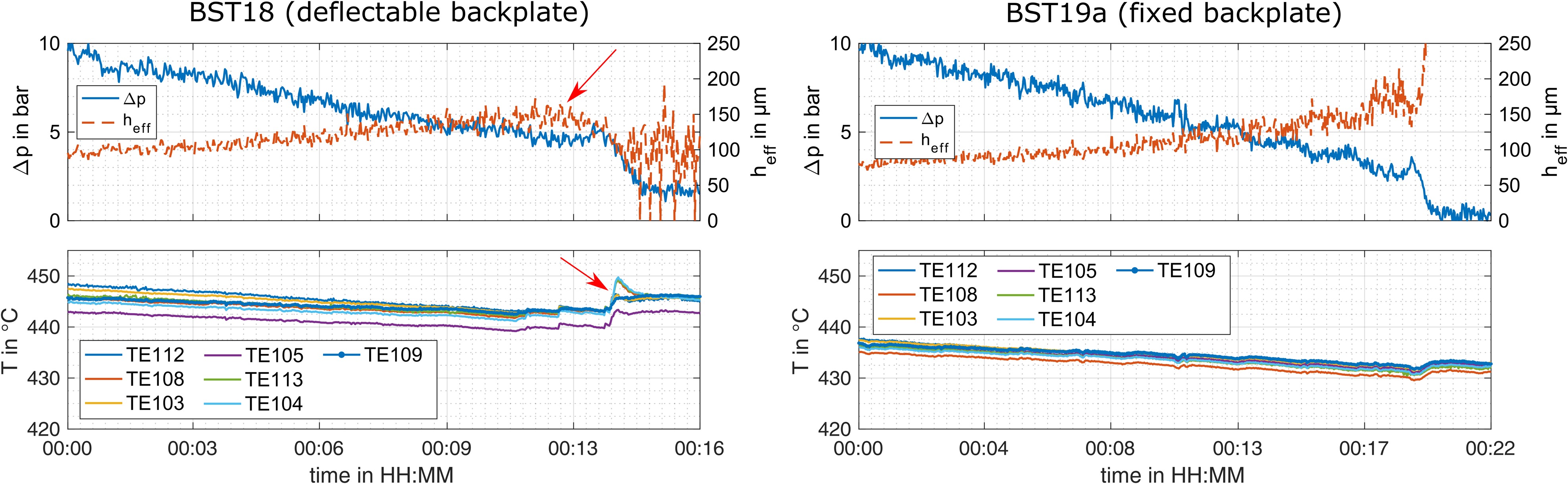
Additionally the trend of the shaft temperatures in Figure 9 reveals an initial peak followed by an increased shaft temperature for the further reduction of the pressure difference during BST18. Since this effect is not present during the pressure variations of BST19a, this behaviour can be adressed to the closing action of the backplate of PABS. The further compression of the bristle pack leads to an increased radial stiffness and therefore an increased heat generation.
For low pressure differences, the orifices for determining the mass flow are not able to resolve the actual leakage which leads to fluctuations of the effective clearance as seen in Figures 8 and 9. Based on this circumstance the values for the effective clearance are blanked for pressure differences Δp < 1 bar.
Furthermore it should be mentioned that the absolute values of the effective clearances and temperatures can not be compared directly for BST18 and BST19a, since wear effects influence the performance of the seals with increasing operational time.
Sealing performance during testing period
To underline the performance of the pressure-actuated seal, the development of the effective clearances heff and achieved difference pressure Δp for all seals under investigation during BST18 are presented and compared to those of the new seal PABS. Figure 10 depicts the effective seal clearances before and after the eccentricity tests Ex1 to Ex3 conducted during BST18. In each case, the maximally achieved pressure of the HP-Chamber pHP,max and a shaft speed of n = 10,000 rpm were set up. These sections were chosen for the comparison since the eccentricities have a significant impact on seal behaviour and deterioration due to the stresses applied to the bristle packs of the seals.
Figure 10.
Maximum pressure of the HP-chamber, difference pressures and effective clearances over the testing period of BST18.
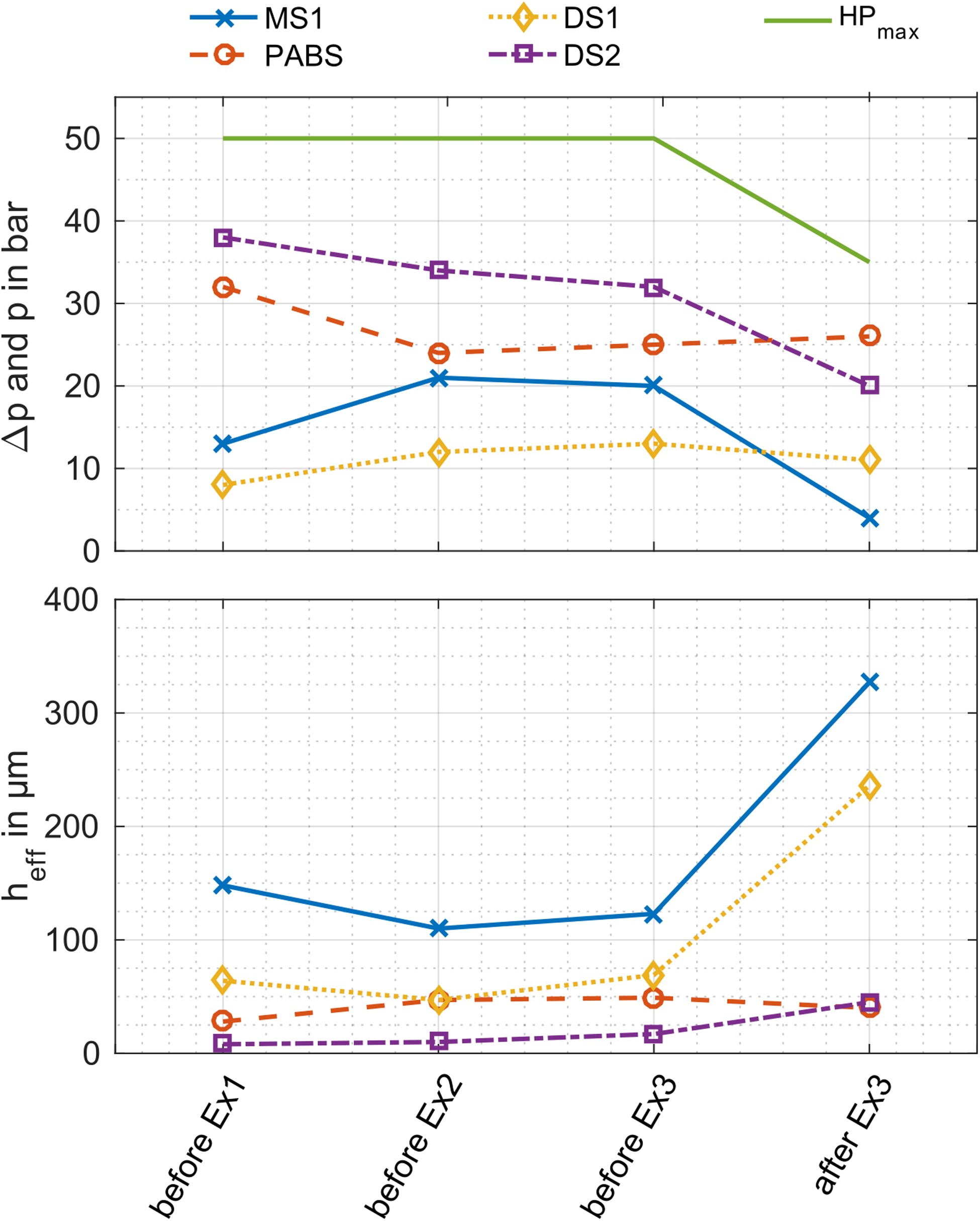
For the first test Ex1 under comparatively low pressure conditions and an eccentricity of ex = 0.3 mm only for seal PABS with the pressure actuated backplate a negative impact on the performance can be seen. The rise of heff from 28 µm to 47 µm, nearly 70%, indicates an increased deterioration of the seal. Furthermore, the pressure difference across the seal is significantly reduced from 32 bar to 24 bar, whereas MS1 takes over the proportionate pressure load. The second eccentricity test Ex2 with a pressure load pHP = 30 bar and ex = 0.3 mm had a comparatively weak effect on the seals MS1, DS1 and DS2 while the effective clearance of PABS was not altered.
A significantly larger influence on seal performance can be observed for the third eccentricity test Ex3. Due to the high pressure load of pHP = 30 bar in combination with an eccentricity of ex = 0.5 mm, this was the most demanding test for the four bristle packs. With the exception of seal PABS comprising the pressure-actuated backplate, a significant increase of the effective clearance up to nearly 200% for the seals MS1, DS1 and DS2 are observed. At the same time, a decrease of the achieved pressure differences for the three seals can be noticed. On the other hand, seal PABS slightly reduced its effective clearance in combination with a slight increase of the pressure load. Since the stress on the seals increased with each eccentricity test, it is remarkable that the performance of PABS was not compromised during the tests Ex2 and Ex 3.
Subsequent analysis of the radial clearances
Following the hot steam test BST18, the influence of the testing programme on the radial clearances of the seals and therefore the seals deterioration was evaluated. For this purpose, the inner diameters of the seals were measured and compared to the initial values. The results are depicted as the radial clearance cg in Figure 11.

Due to the elevation of the HP-chamber during the eccentricity tests of BST18, the lower partial ring of the installed seals is stressed due to rubbing, while the clearance between the shaft and the upper partial ring of the brush seals is increased. Since the lower partial ring is expected to show an increased deterioration, a distinction is made between the radial gap for the upper and lower partial rings of the seals.
As assumed, the radial clearances of DS1 and DS2 for the lower partial ring have increased by 0.1 mm and 0.2 mm more than for the upper half of the seal. In case of MS1, the clearance increased by 0.1 mm compared to the state before the testing under hot steam conditions. Solely for PABS, the radial clearance for the upper partial ring is 0.1 mm wider compared to the lower half of the seal. In combination with the findings that the effective clearance of PABS increased during the first eccentricity test, the knowledge that PABS has a negative inclination in the upper partial ring and the fact that the seal carried a pressure difference of 4 bar during the first eccentricity test, it can be assumed that the performance deterioration was mainly caused by wear due to bristle oscillations of the upper seal half during the first eccentricity test. Although the pressure-actuated backplate was closed during the first eccentricity test, the findings of the preliminary investigations show that the compression of the bristle pack caused by the backplate is only partially sufficient to suppress bristle oscillations. It can therefore be expected that seal PABS comprising the deflectable backplate, would even have shown a comparatively better performance if the axial inclination in the upper half had corresponded to the nominal value of φ = 0°. This would have reduced bristle oscillations and wear during the eccentricity test at low pressure differences.
Conclusions
The increasingly flexible operation of steam turbines also requires the adaptability of turbine sealing systems. For this purpose, a newly designed brush seal was introduced and investigated. The aim of the concept is to combine the characteristics of low and high inclined brush seals which are either suitable for high or low difference pressures. Negative properties, which can occur for brush seals under certain conditions, such as bristle oscillations, should be excluded. For this purpose a low inclined seal is pre-compressed by a pressure-actuated backplate for the low pressurized state. With increasing pressure difference the backplate is deflected in downstream direction, releasing the pre-compressed bristle pack.
Preliminary investigations were conducted at a test rig without rotation, supplied with compressed air. The analysis of the leakage mass flow and the analysis of the axial behaviour by an optical access revealed that bristle oscillations were reduced by up to 90% while the leakage decreased by up to 40% due to the pressure-actuated backplate compared to conventional seal designs.
Based on the findings of the preliminary investigations the novel design was adapted for the application in the hot steam test rig of the TU Braunschweig. Two tests at the hot steam test rig were conducted with the aim to prove the functionality of the novel seal under realistic conditions comparable to those in a steam turbine. For this purpose pressure variations, shaft speed variations and eccentricities of up to 0.5 mm were conducted.
Due to the comparison of the two tests with axially deflectable and fixed pressure-actuated backplate, indications for the actual movement of the backplate are derived from the trend of the effective clearance and the shaft temperatures during pressure variations.
Furthermore, the sealing performance of the novel seal during the first test under hot steam conditions was evaluated by comparison to the performance of the other seals under investigation. Therefore, the development of the effective clearance in combination with the pressure difference across the seals is analysed. It is shown that the novel seal with pressure-actuated backplate has obviously improved capabilities to be resilient against shaft eccentricities compared to the other seals. The seal was able to maintain a low leakage in combination with high difference pressures throughout the entire testing period, while the other seals showed a significant rise in the effective clearance in consequence of the stress of the eccentricity tests. The final examination of the radial clearance of the seals of the first hot steam test revealed that the improved sealing concept experienced comparatively low wear despite the continuously high pressure differences during the test.
Altogether, the novel pressure-actuated brush seal successfully demonstrated its functionality and positive properties for operation under turbine like conditions. It showed improved properties regarding a high leakage performance and an advanced capability to avoid deterioration due to shaft excursions. Moreover the axial inclination of the bristle pack is identified as a critical parameter for the achievement of these positive properties.
Nomenclature
B
bristle pack width in mm
BOS
oscillating bristle pack width in mm
Bpmm
bristles per mm
d
bristle diameter in mm
ex
eccentricity in mm
cfh
fence height in mm
cg
radial clearance in mm
heff
effective clearance in mm
γ
heat capacity ratio
lr
free radial bristle length in mm
λ
lay angle in °
mass flow in kg/s
n
shaft speed in rpm
φ
axial inclination in °
p
static pressure in bar
pd
pressure downstream of seal in Pa
pu
pressure upstream of seal in Pa
pHP
pressure in HP-chamber in bar
ρ
packing density in Bpmm
r
radius of the rotor in m
Rs
specific gas constant in J/(kgK)
T
static temperature in °C
Tu
temperature upstream of seal in K