
Introduction
Unshrouded or open impellers have long been used in centrifugal compressors when high head levels or high-pressure ratios are required. They are very common in turbochargers, gas generator sections of gas turbines and integrally-geared compressors. Having no shroud or cover, these impellers can operate at higher tip speeds than conventional shrouded or covered wheels due to the lower inherent stresses, i.e., without the cover pulling outward during operation. In some gas turbine or turbocharger applications, unshrouded impellers operate at tip speeds more than 2,000 feet per second (610 meters per second).
One of the most important factors in attaining high performance from unshrouded impellers is the tip clearance between the top of the rotating blades and the adjacent stationary wall or shroud. As this so-called tip clearance increases, the performance of the impeller deteriorates. Further, if the clearance becomes excessively large, it might not be possible to aerodynamically operate the compressor in a stable fashion.
As a result of the above, unshrouded impellers have historically been used sparingly in center-hung multi-stage, single shaft applications. One example of their successful use is in charge gas compressors for ethylene production or similar processes. In all known cases, such compressors included a maximum of two unshrouded impellers in series or at opposite ends of a double-flow rotor.
The demand for higher pressure ratios in a single compressor has led to a renewed interest in using multiple open impellers in single shaft compressors. The increased pressure ratio and volume reduction attainable by unshrouded impellers allows more work to be done on the flow with a smaller number of impellers. This permits a reduction in the compressor footprint or case size, thereby reducing the space required for the compression package. This is of particular interest in low molecular weight applications, where gas properties limit the ability to achieve high pressure ratios with conventional shrouded impellers.
This paper describes recent experiences with a compressor being developed for a relatively low molecular weight application with a focus on reducing the size of the compression package. To attain the necessary pressure ratio while simultaneously reducing the case size, it was necessary to operate at tip speeds higher than could be tolerated by shrouded impeller designs. Therefore, unshrouded impellers were applied. The authors’ company has extensive experience with such impellers in both integrally-geared and single-shaft arrangements. However, much of that experience has been in single-stage, overhung configurations.
The unit being developed was a six-stage back-to-back, single-shaft compressor with three open impellers in series in the first section and three closed impellers in the second section. Attempts to apply existing unshrouded impeller designs were unsuccessful because the available impellers required too much axial space, resulting in unacceptable rotordynamics. Therefore, it was necessary to develop new, shorter axial length impellers to reduce the bearing span to the length needed for an acceptable rotordynamic solution.
Regarding the new impellers, a novel knowledge-based impeller design system had recently been developed by the authors’ company and an overview of this system is provided in this paper. The new system was used to create the new impeller geometries and CFD simulations were done to assess the viability of the new designs. Additional iterations were completed through the design and analysis process until all required assessment criteria were met. The CFD-based performance characteristics were then verified via rig testing. Results from these tests are provided.
The next step was to implement the new impellers and their associated stationary components into the multistage compressor. Information is provided on the mechanical and aerodynamic design considerations for the new impellers and the associated stationary components in the compressor. As noted, maintaining an acceptable tip clearance above the open impellers is essential to achieving good performance. This becomes a greater challenge when there are multiple unshrouded impellers in series because there are greater axial deflections due to varying thrust loads and thermal effects. Therefore, special provisions had to be developed to maintain better control of the running clearance on the three unshrouded impellers. An overview of the steps taken to control the impeller tip clearance is provided.
A full-size prototype of the six-stage compressor was built and subjected to an ASME PTC-10 type 2 sectional test to demonstrate that the unit was aerodynamically and mechanically acceptable and that the tip gap control measures was functioning properly. An overview of these results is provided. Finally, comments are offered on the viability of using multiple unshrouded impellers on a single shaft in process market applications as a result of this development effort.
Aerodynamic design
General considerations on model testing and component qualification
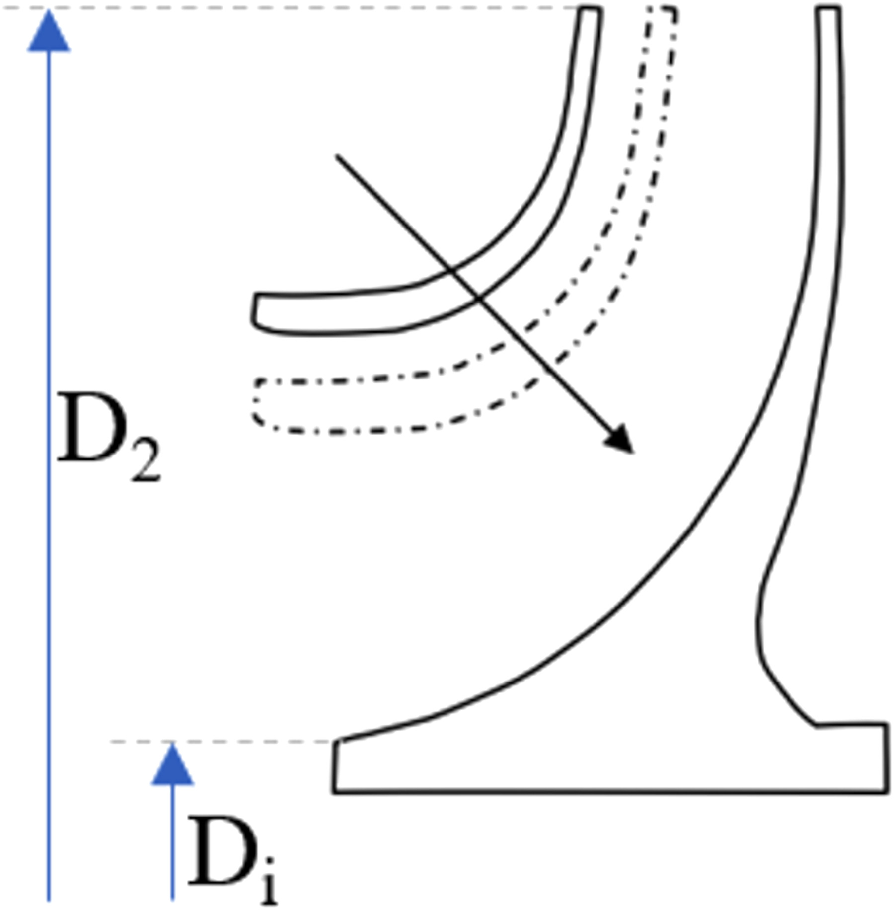
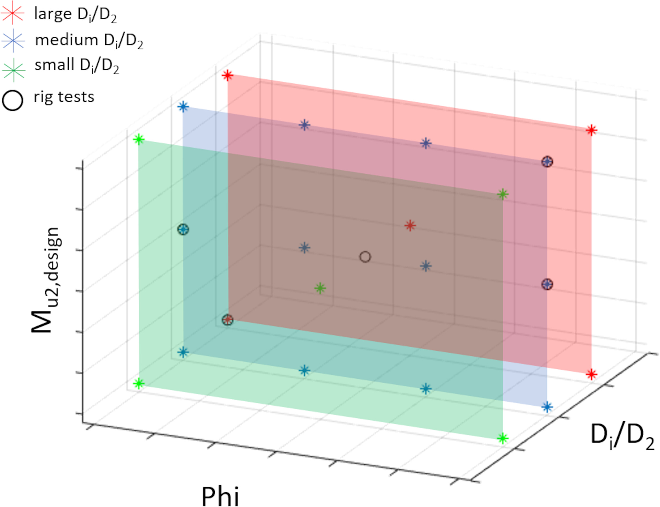
In developing the new stages, the authors’ company employed standard industry methodologies with regard to developing the impellers, diffusers and return channels. This involved the typical application of bulk flow computer codes or referencing prior designs to establish the initial flow path dimensions. As is also standard practice, computational fluid dynamics (CFD) was used extensively to optimize and/or assess the performance of the newly developed components and sort out the best designs. However, because CFD is not yet a virtual test rig, when making the decision to release of a new impeller family into production, there is still no way around experimental validation via model testing (Sorokes and Welch, 1991). Because one impeller family can cover a certain range of flow coefficients, hub to tip ratios Di/D2 (see Figure 1) and Mach numbers Mu2, it is not possible or necessary to rig test every possible design. Instead, a reasonable number of tests is determined depending on the size of the family’s application map. The test data is then augmented by a matrix of CFD simulations which are calibrated to match the rig data. Figure 2 shows the CFD and test matrix of an impeller to be validated via testing. Each point in the matrix represents a speed map with four different speed lines, each comprising eight operating points. The distribution of the test and CFD points depends on the expected performance gradients in the application map and where the most challenging conditions are expected. For example, during the qualification of a new high flow coefficient and high Mach number impeller family, much attention must be paid to the upper right corner of the application map (highest flow coefficients and Mach numbers).
The test rig data and the CFD results serve to validate the impeller family performance. It is also used as a basis to calibrate the compressor performance prediction code. After a calibration is finished, the physical based models in the tool ensure an accurate performance prediction over the whole application range for that component. To ensure that good test rig data are achieved special focus is placed on the design of the test vehicle. Areas of focus included:
The flow path of the rig tested stage must follow the design rules used in a real machine, e.g., the 90° bend upstream of the impeller should be as tight as in a typical multistage arrangement.
The tip clearance between rotating impeller blades and stationary shroud contour must be similar to what can be realized in a real compressor.
The actual tip clearance must be measured (axial and radial) and considered during aerodynamic performance calibration. A tip clearance changes from 0.3% of the impeller diameter to 0.2% of the impeller diameter can result in a large difference in stage efficiency, i.e., the larger tip clearance will result in a lower the efficiency (Senoo and Ishida, 1987; Sorokes et al., 2017; Brun and Kurz, 2019).
Steady state conditions must be reached during testing and the test rig needs to be insulated to ensure accurate temperature measurements.
Vibration probes and fast-responding pressure transducers up and downstream of the impeller are needed to detect any possible unsteady flow to ensure the stage achieves the required flow range without the presence of any forms of stall (Senoo and Kinoshita, 1978; Frigne and Van Den Braembussche, 1983; Sorokes and Marshall, 2000).
For core stage tests special attention was paid to the following points:
The stage outlet is at a specific location in the vaneless diffuser, e.g., at 1.5 times impeller tip diameter. Because of span-wise gradients in the flow field, data must be taken via a traverse probe at different span positions to get representative performance quantities. Depending on diffuser width and expected inhomogeneity of the flow profile five to ten span wise positions are generally taken.
Cyclic symmetry must be ensured at the stage outlet. This is to ensure that the traversing probes at fixed circumferential positions measure representative data. Cyclic symmetry can be proven via pressure taps around circumference of the test rig.
Overall, the following test data are taken:
total pressure and total temperature at stage inlet flange at 4 different positions
total pressure and total temperature (traversing probes) at 2 different radial positions each time at 2 different circumferential positions 60° away from each other (and 5 different span positions)
static pressure at three different radial positions in the diffuser at each time 8 different circumferential positions
fast responding pressure data at impeller inlet and in the vaneless diffuser
Having presented an overview of the test rig and the test philosophy, attention will now turn to the design of the new impellers.
Impeller design
As mentioned in the introduction, the task was to develop a compressor for a relatively low molecular weight application with focus on reducing the size of the compressor casing. To attain the necessary pressure ratio while simultaneously reducing compressor size, it was necessary to operate at high tip speeds. To remain within allowable impeller stress limits, the new designs had to be unshrouded. However, the available unshrouded impellers in the OEM’s portfolio had been designed for high Mach numbers and thus required relatively large axial stage spacings. Use of these would have led to unacceptable rotor dynamics for the required six-stage configuration at the prescribed rotor speed. Therefore, new axially shorter impellers were developed for the first section of the compressor. The challenge was to ensure acceptable aerodynamic performance combined with as short as possible axial length for each stage. To meet this requirement each impeller was designed for its specific boundary conditions to achieve an optimal compromise between impeller length and performance. For that reason, a novel knowledge-based impeller design system was used to create the new impeller geometries.
Before getting into details on the new impeller designs, it is important to note that the new stages also employed a different philosophy with regard to the definition of an impeller (or stage) family. As a general rule, conventional families are comprised of impellers that use a fixed impeller blade shape. The impeller hub and shroud contours of a family are adapted to the actual boundary conditions, such as flow rate, molecular weight of the gas and hub-to-tip ratio Di/D2 (see Figure 1). Although the blading of each family was developed for a specific set of boundary conditions, by adapting the contour it is possible to use one impeller blade shape over a range of flow coefficients, Mach numbers and shaft sizes.
Design is a series of compromises, and this approach has a few disadvantages. All impellers out of such a family have a very similar axial length and the more the actual boundary conditions deviate from the initial boundary conditions for the blade development, the more performance compromises result.
The new knowledge-based approach overcomes those disadvantages. Knowledge based impeller (KBI) families are not characterized by their use of a fixed blade shape, but by a “fixed” set of rules which govern the impeller geometry generation. This increases the possible application range of an impeller family and allows for better adaptation of every impeller to the actual boundary conditions (fit for purpose). The impeller length is no longer constant; the lower the Mach number and/or the flow coefficient, the shorter the impeller. In addition, the blade shape is adapted to the actual operating conditions leading to better performance. The impeller knowledge base is comprised of functions which describe the blade angle distribution, blade outlet width, hub and shroud contour as a function of inlet relative tip Mach number, flow coefficient and bore diameter.
Contrary to custom-designed impellers, this comes along without compromises regarding the reliability. All impellers in each family follow the same rules. Thus, by rig testing a reasonable number of designs in a newly developed family, a qualification of the complete family is possible prior to the release. Another advantage of using a rule-based system is that all defined rules can be stored in the knowledge database. This knowledge database improves with the development of every new impeller family and leads to consistent designs over the whole product portfolio.
The compressor being addressed herein was the first utilizing the new design approach. The knowledge base, therefore, was generate based on the existing impeller families within the OEM’s portfolio, including both shrouded and unshrouded families. The result was that the impeller length could be reduced for the given boundary conditions compared to the existing unshrouded impellers. Because of the low Mach number, an axial length reduction of 30 percent was achieved in the first process stage of the compressor.
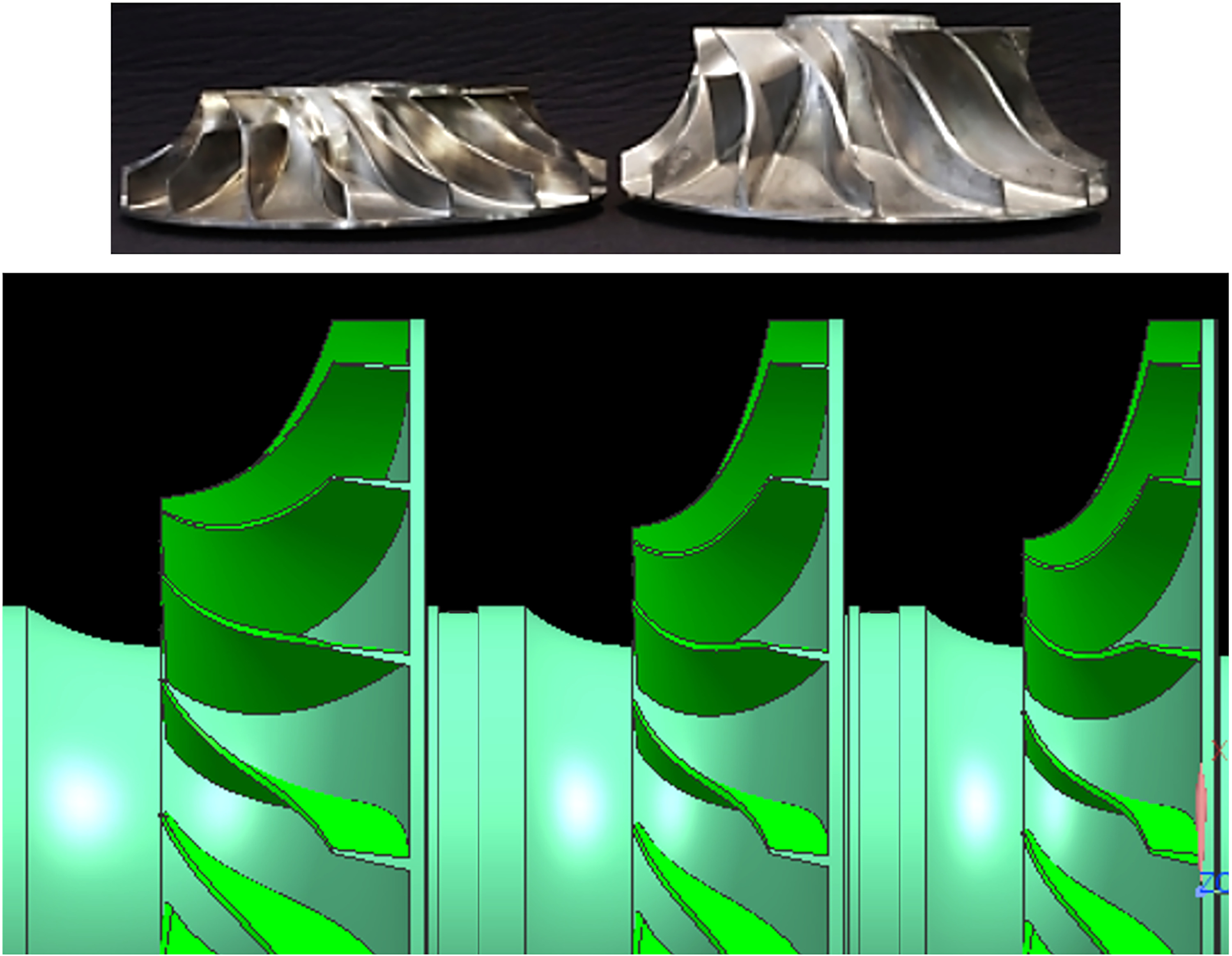
The picture on the left in Figure 4 shows one of the new impellers in comparison to an existing unshrouded impeller developed for higher Mach-Numbers. The lower Mach design is shorter in axial length. On the right-hand side, all three new impellers of the first compressor section are shown. Although all three impellers are from the same impeller family, the impeller length continuously decreases from stage to stage with decreasing Mach-number and flow coefficient.
Figure 4.
Picture of unshrouded impellers designed for low and high Mach numbers (left); 3D model of the three unshrouded impellers of the first section.
Numerical simulations were conducted for all three impellers of the new family. The results showed that the head, efficiency, range, and mechanical strength of the new designs were comparable to the exiting designs, except 30% shorter. Thus, in a first validation phase, scaled down versions of two of these impellers (first and second stage) were manufactured and rig tested to verify the CFD prediction.
Rig test results
A comparison of the CFD prediction and test data for polytropic efficiency, polytropic head coefficient and work input coefficient for the 1st test are shown in Figure 5. The tested stages are close to the upper flow coefficient limit of the new impeller family. The design Mach number is 0.65. The comparison in Figure 5 is for the design Mach number and a higher one of 0.88. For the design Mach number, the agreement between CFD and test data is very good. Head, efficiency level and work input match well with CFD predictions. In addition, the operating range prediction is very accurate.
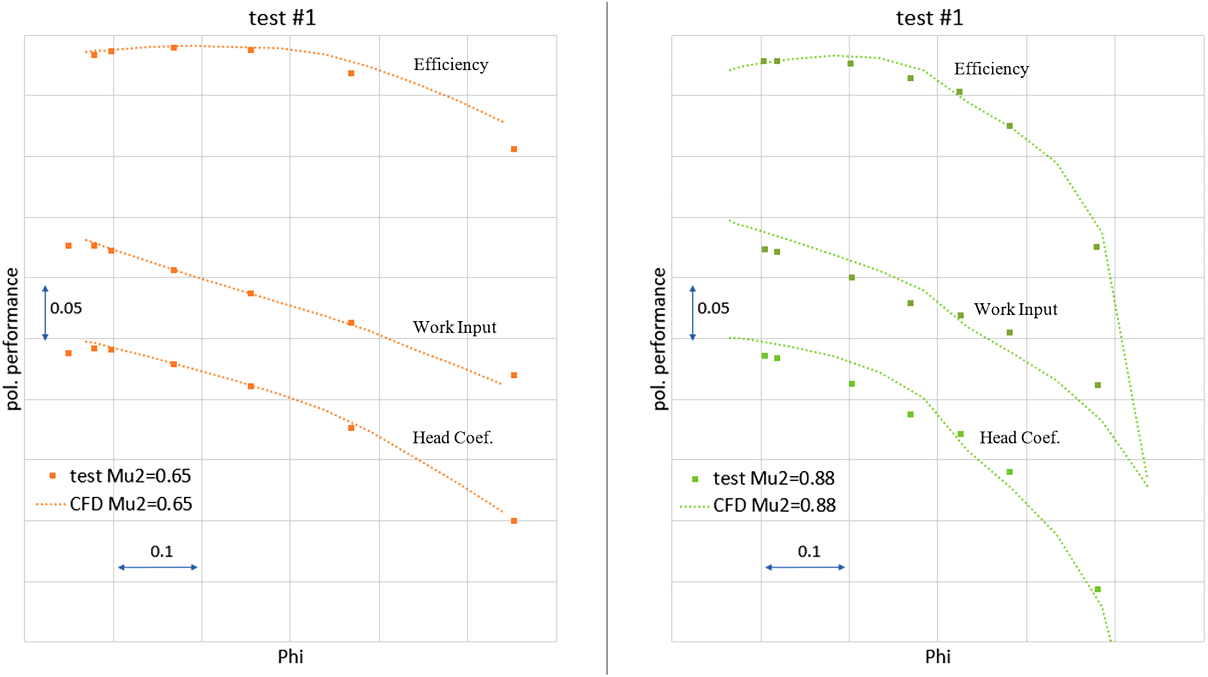
For the Mach number of 0.88, the agreement between CFD and test is slightly worse. Range and efficiency are still well predicted, but work input and head are not. The OEM’s experience shows that as long as the impeller loading is not too high, the CFD prediction is accurate. On the contrary, for Mach numbers above the design Mach number, leading to a high impeller blade loading, CFD is too optimistic with respect to head levels. In this case, the predicted head coefficient is 3% too large. This underscores the need for experimental data in the qualification of a new component. The small kink in the CFD performance curves for Mu2 = 0.88 are caused by a separation because of the very high impeller loading (actual Mu2 is 35% higher than design Mu2).
Unfortunately testing of the second stage of the first section, did not meet expectations; test and CFD results did not match well as the efficiency fell short of prediction.
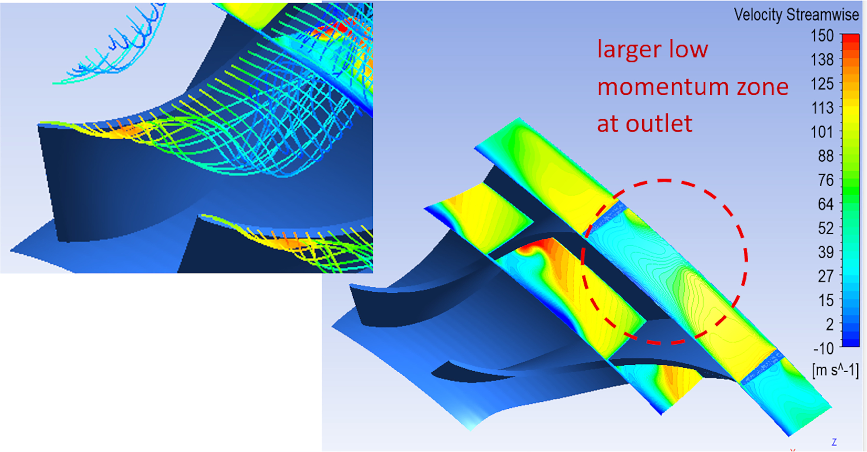
To identify the cause for the efficiency shortcomings a comprehensive root cause analysis was conducted. The reason for the deviation was found to be a difference in the radial clearance values used in CFD versus what was tested. A difference of 0.1% D2 was sufficient to cause the inaccurate CFD prediction. Running the same setup with the actual test clearance led to a much better agreement between CFD and test. The more accurate CFD setup was used to better understand the shortcomings. A more detailed examination of the flow field revealed that the impeller blade loading in the inducer section was too high leading to an impeller blade design that was overly sensitive to the radial tip clearance at the impeller eye.
CFD results with the “as tested” radial tip clearance are shown in Figure 6. A tip vortex forms immediately downstream of the leading edge leading to a large low momentum zone at the impeller outlet (right hand picture in Figure 6) and the low efficiency level.
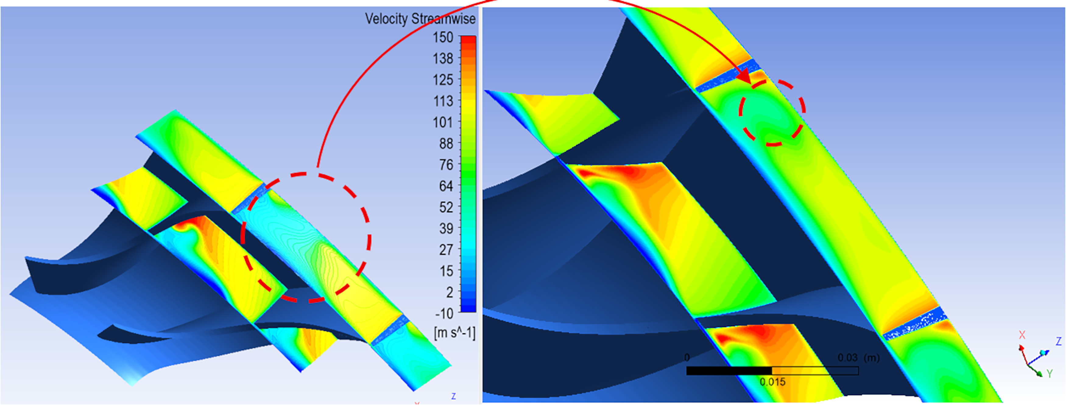
To solve this problem, the blade loading was adjusted by changing the blade angle distribution and shifting the high load out of the inducer region of the impeller. As a result, the size of the tip vortex was reduced leading to a much more homogeneous flow field at the impeller outlet while maintaining the other performance quantities like range and head coefficient. Contour plots of the streamwise velocities at two different radial positions in the impeller are shown in Figure 7. The left plot shows the original design; the right-hand plot shows the revised design. The color code is the same in both pictures. The size of the low momentum zone at the outlet of the impeller was reduced by the improved blade loading and predicted efficiency went up by ∼4%. The revised design met the performance requirements even with the larger radial clearances. Thus, another rig test impeller was manufactured, and tested to validate the CFD prediction.
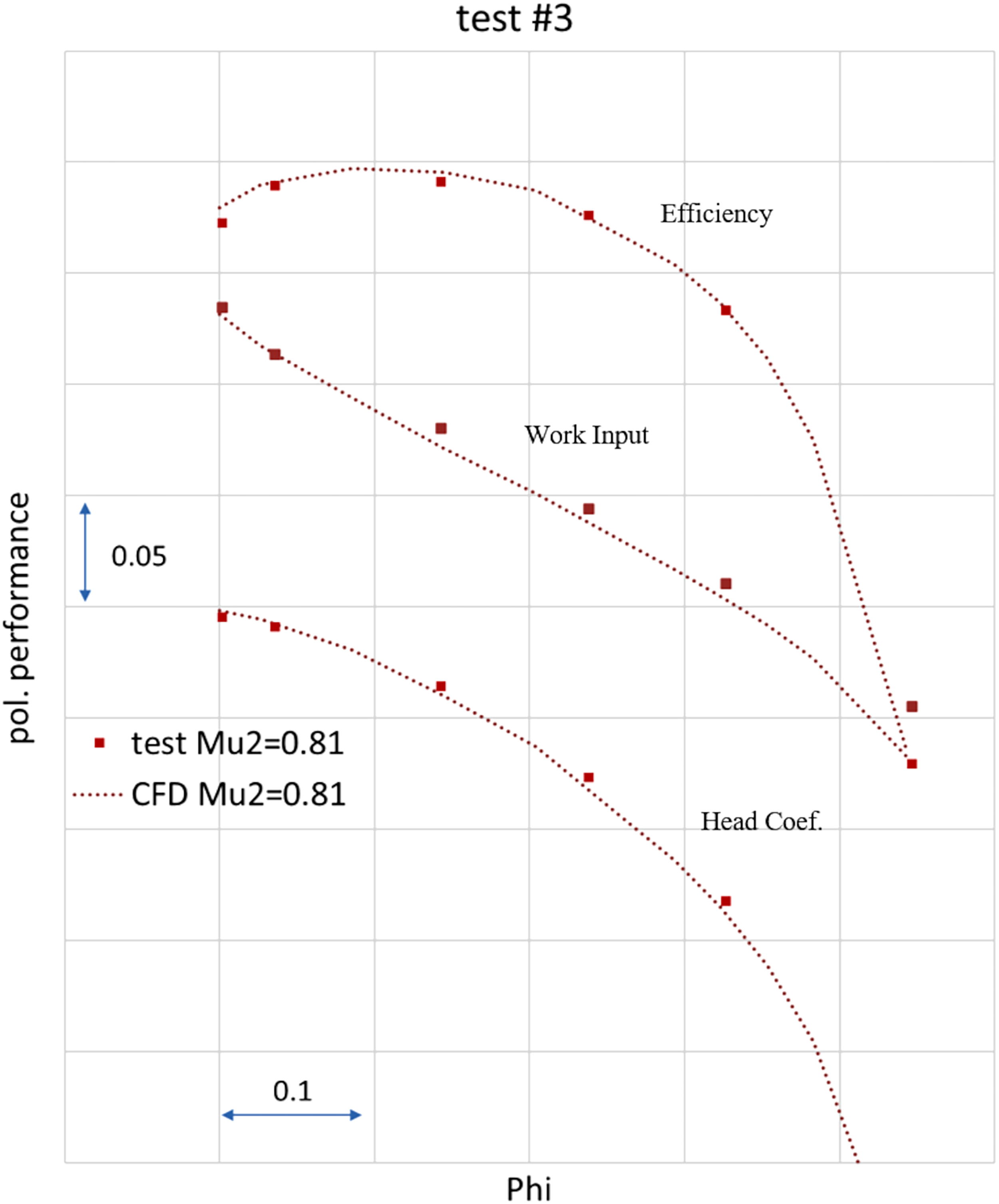
The comparison of test data and CFD prediction for the redesigned impeller are shown in Figure 8, again at medium flow coefficient. The design Mach number is 0.81. Prediction and test are in good agreement.
As stage 1 and 2 are from the same impeller family the modifications of blade loading also affect stage 1 impeller design. For this flow coefficient however the changes regarding the design were small. The influence on the performance was evaluated via CFD and found to be negligible.
Finally, please note that the blade loading knowledge gained for the axially shorter, unshrouded impellers was incorporated into the knowledge base for future use.
Diffuser design considerations
In establishing the diffuser geometries, several factors were considered. One of the most important was the impeller exit flow angle. In this situation, in designing the new impellers, steps were taken to keep the impeller exit flow angle in the same range as in other impellers from the OEM’s product lines. However, attention was still given to the resulting flow angles in the vaneless diffuser or in the semi-vaneless space upstream of a vaned diffuser. As has been well-documented, if the flow angle in these locations becomes too tangential, diffuser rotating stall will occur, resulting in undesired sub-synchronous radial vibrations and/or pressure pulsations within the compressor and/or piping system. To avoid such phenomena, the overall vaneless diffuser width or width of the diffuser passage in the semi-vaneless space must be reduced so that the flow angle does not exceed the so-called critical angle for diffuser stall onset. However, care must also be taken to not “over-pinch” the diffuser as this can result in a reduction in the peak attainable efficiency, especially when using a vaneless diffuser.
CFD simulations were performed to assess the performance impact of the different diffuser styles and to ensure that there was no evidence of the flow field features that suggest the onset of rotating diffuser stall. The effectiveness of the various diffusers was also verified via the prototype tests that will be described in the sections which follow. As noted, there were dynamic pressure transducers installed during the rig testing. These probes also showed no unusual pressure pulsations during the validation testing.
Prototype
The scope of this program included engineering, manufacturing, assembling, and testing a full-size prototype.
The unit tested had 125 mm (4.92 inch) five shoe tilt pad journal bearings, 135 mm (5.31 inch) tandem dry gas seals, 305 mm (12.0 inch) self-leveling thrust bearings. Additionally, the unit has ∼470 mm (18.5 inch) impeller diameter and a 1.46 meter (57.5 inch) bearing span. The shaft power was approximately 13 MW (17,500 HP). The unit was tested using a parallel axis gear with a gear ratio of 3.13, that was driven by an OEM owned turbine. The 30% reduction in the first section stage space increased the rotor natural frequency by 20% allowing the unit to run faster and still comply with API separation margins. To satisfy the customer requirement for acid wash, the rotor was manufactured out of 15-5 martensitic precipitation-hardening stainless steel (see Figure 9).
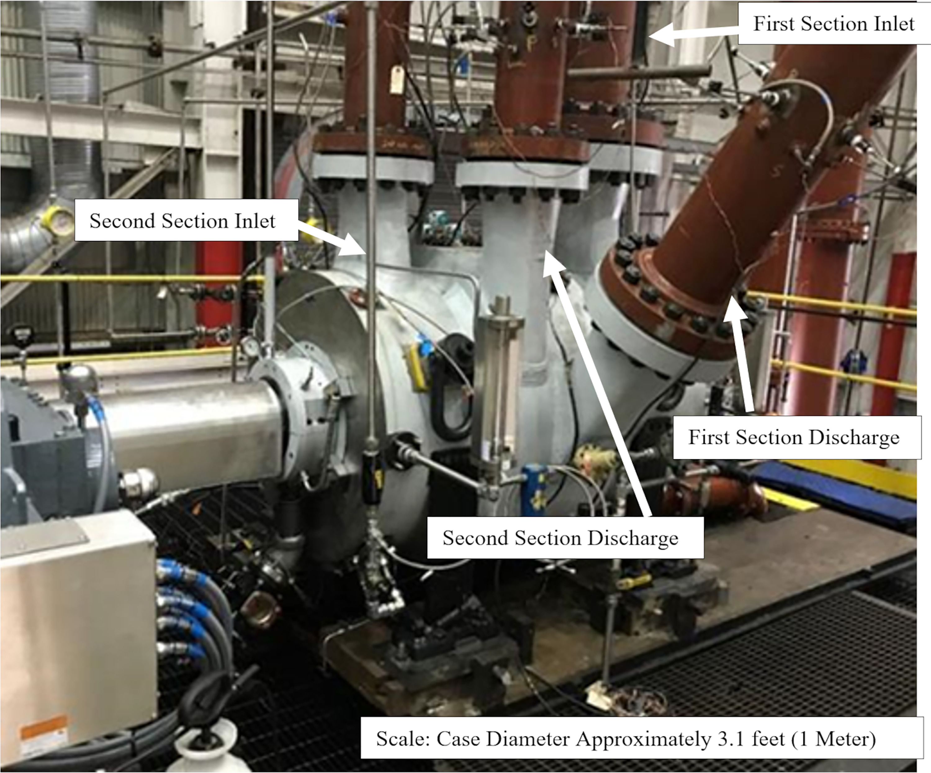
As discussed earlier, the back-to-back compressor included a 6-stage (3 + 3) rotor using three open (unshrouded) impellers in the first section. This was the first time in the authors experience where three open impellers were utilized in succession. Process section one of the back-to-back is the low-pressure stage and is located on the service end side of the compressors.
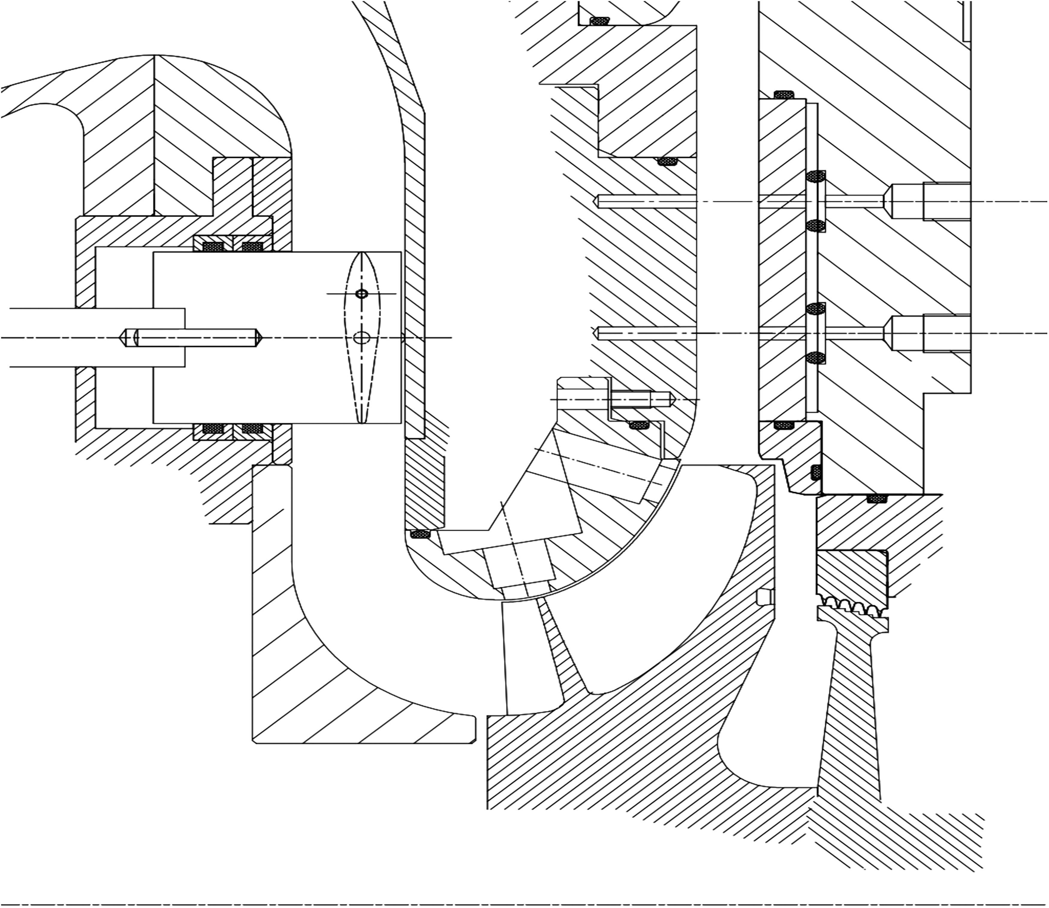
To control impeller tip gap clearance and preserve aerodynamic efficiency, the open impellers employ a stationary contour ring with an abradable coating. These three contour rings were rail fit into the diaphragm and shimmed at assembly to avoid rubbing but maintain a tight clearance. At start-up the rotor will heat up faster than the stator, the compressor configuration allows the open impellers to grow away from, rather than into, the contour rings during transient periods. The back-to-back unit was driven from the second section discharge with the thrust bearing on the inlet end of the machine. Starting cold as the rotor comes to speed it will warm faster that the corresponding stationary components. With the thrust bearing on the inlet side as close as possible to the open impellers the rotor will grow away for the stationary contour rings. The compressor feet are anchored to the base plate at the inlet end. As the unit reached thermal steady state the impeller tip gap will close to a predetermine value. Using a hot-to-cold axial growth conversion the contour rings were shimmed at assembly to a specific value.
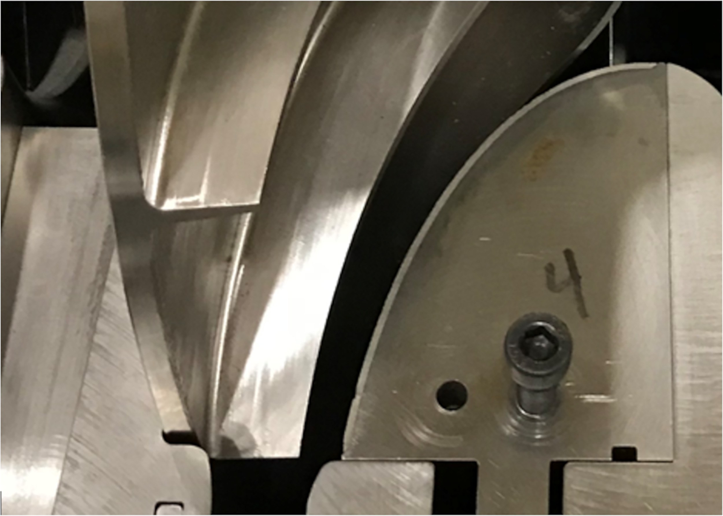
The contour rings were split, and a 180-degree section is shown in Figure 10. Figure 11 shows an open impeller in close proximity to the contour ring.
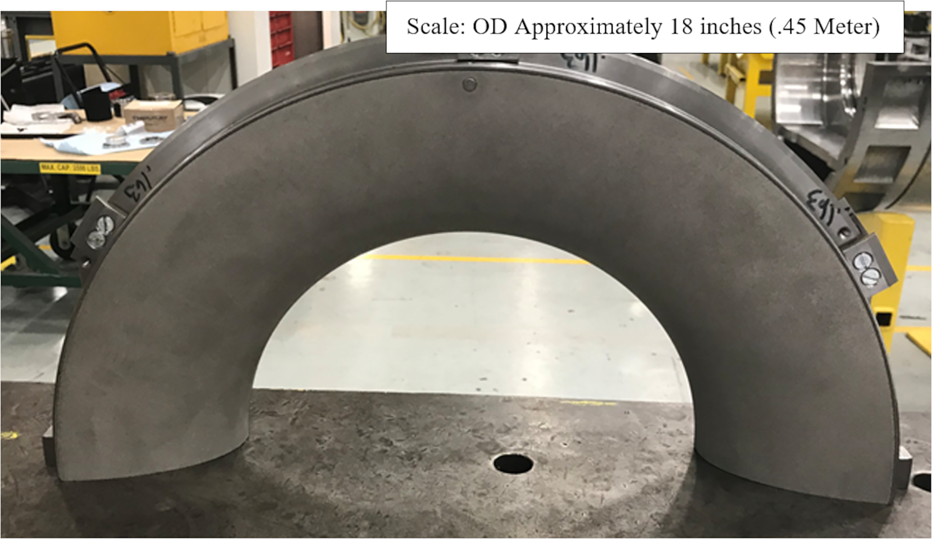
Figure 11.
Unshrouded impeller with contour ring (rotor & contour ring not in final running position).
Through the testing, vibrations were monitored looking for signs of rubbing. None were detected. Post-test inspection also showed that no rubbing had occurred.
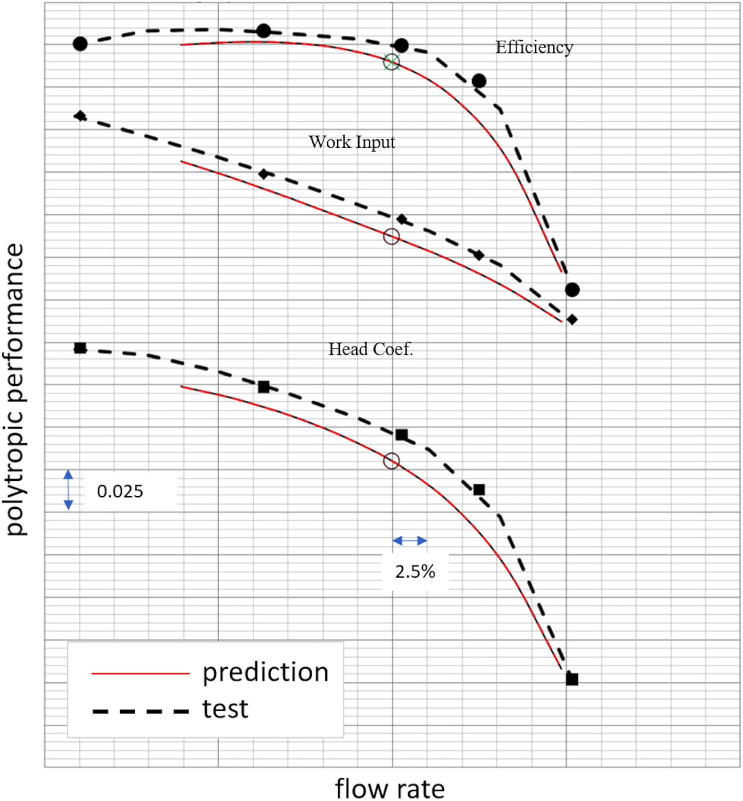
The ASME PTC-10 Type II (Compressors and Exhausters, 1974) test data compared against expectations for the first section of the prototype comprising the three unshrouded impellers is shown in Figure 12. Efficiency (curve at the top), work input coefficient (middle curve) and head coefficient (bottom curve) are given. The general agreement of prediction and test data is very good. As-tested efficiency was 1% higher compared to the prediction. Agreement of work input and head shape are good. As-tested work input and head are 2–3% higher than prediction. The predicted maximum capacity of the section matched the as-tested flows on the overload side of the curve and performed well at lower flow when compared to expectation. The surge margin of the as-tested curve was even considerably larger than the expectation. One reason for this might be that you can go beyond the point where a single stage in the section reaches maximum head and still have stable operating conditions. This is not possible in a single stage arrangement as those wheels were rig testes before. Those rig tests served as basis for the performance prediction (expectation). This might be the reason why it is on the conservative side regarding surge margin prediction.
The second section of this back-to-back unit utilized convention shrouded impellers that the OEM had extensive experience with. Section two tested well, but for brevity will not be discussed in detail in this paper. Overall, the precited shaft power at the design point was expected to be between 12,659 KW to 12,786 KW (16,976–17,146 HP). The as tested shaft power was 12,667 KW (16,986 HP).
Conclusions
The use of unshrouded impellers to increase the pressure ratio and volume reduction achieved in low mole weight, single-shaft compressor applications was discussed. The aerodynamic and mechanical implications of using multiple unshrouded impellers in series was also addressed. Test results indicate that with proper management of impeller tip gaps good aerodynamic performance can be achieved with three unshrouded impellers in a single process section. The development effort also took advantage of a knowledge-based impeller design system to provide new impeller designs that were optimized as a function of Mach number to provide a 30% axially shorter section without compromising aerodynamic performance. The shorter axial stages in the first section pushed the rotor natural frequency 20% higher, enabling faster rotor tip speeds. Test results from a single-stage test rig and from a full-size prototype testing were provided and generally show good agreement.
Nomenclature
Di/D2
Hub-to-tip ratio
Di
Minimum diameter of impeller hub aerodynamic flow path
D2
Impeller exit diameter
KBI
Knowledge Based Impeller
Mu2 = u2/a0
Machine Mach number
u2
circumferential speed of impeller at impeller outlet
a0
speed of sound at impeller inlet
head coefficient
head related to u22
work input
total enthalpy raise of the stage
flow coefficient
flow rate in m3/s related to u2 and A2 = D22*Pi/4