
Introduction
The blade tip clearance is a crucial factor in the compressor performance (Wang et al., 2020) and the aeroacoustics (Galindo et al., 2015). Driven by the pressure difference between the pressure side and the suction side of the blade, tip clearance flows as jets traverse impeller passages and interact with main flows in passages, causing a series of unsteady vortexes which would deteriorate the compressor performance and increase the aeroacoustic level.
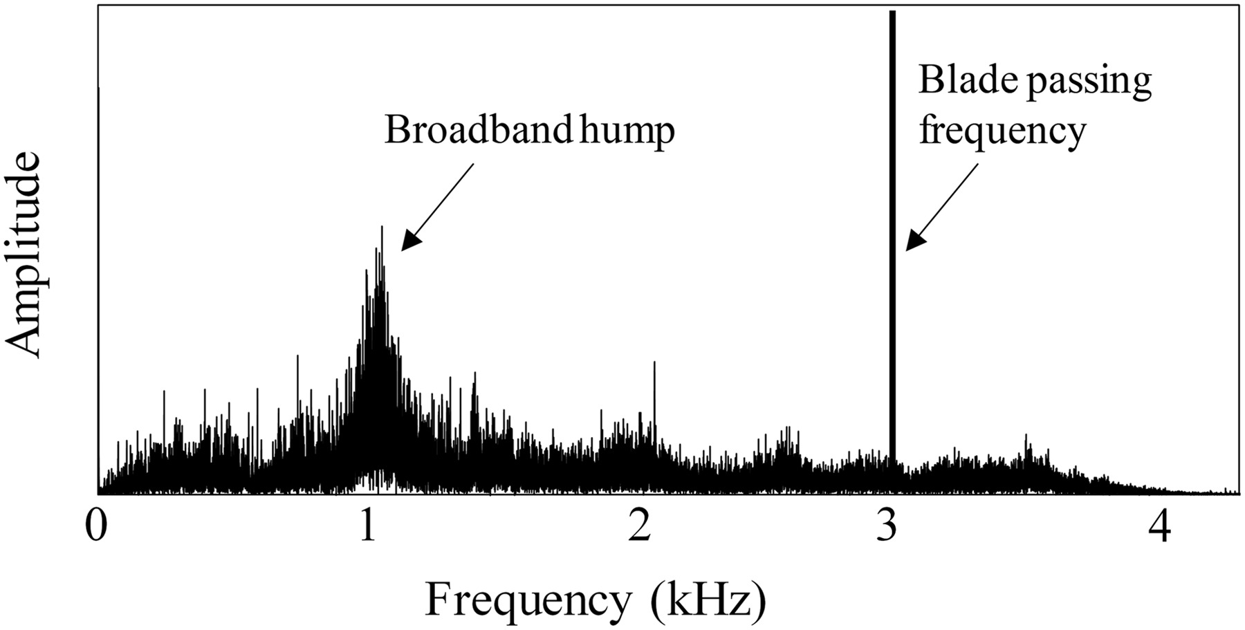
To reveal the influence of tip clearance flow on the compressor performance, many researches have been carried out. Hah (Hah, 2017) found that in a large blade tip gap the tip clearance flow could traverse the blade passage and enter the adjacent blade tip gap forming a double tip leakage clearance flow to deteriorate the compressor performance. Cevik et al. (2016) developed a novel casing treatment to eliminate the double tip leakage clearance flow for reducing sensitivities of compressor performance to the tip clearance variation. Meanwhile, the tip clearance flow would cause noisy broadband aeroacoustics. At a large blade tip clearance, a flow phenomenon termed rotating instabilities (RI) has been observed in axial compressors and centrifugal compressors (Mailach et al., 2001; Pardowitz et al., 2014; He and Zheng, 2018). The representative frequency spectrum of RI is shown in Figure 1 (Young et al., 2012; Day, 2016). The experimental studies on axial compressors of Kameier and Neise (1997) showed that a narrow frequency band below the blade passing frequency (BPF), i.e. RI, significantly increased when the tip clearance was enlarged, and the RI noise could be eliminated effectively by inserting a turbulence generator into the tip clearance.
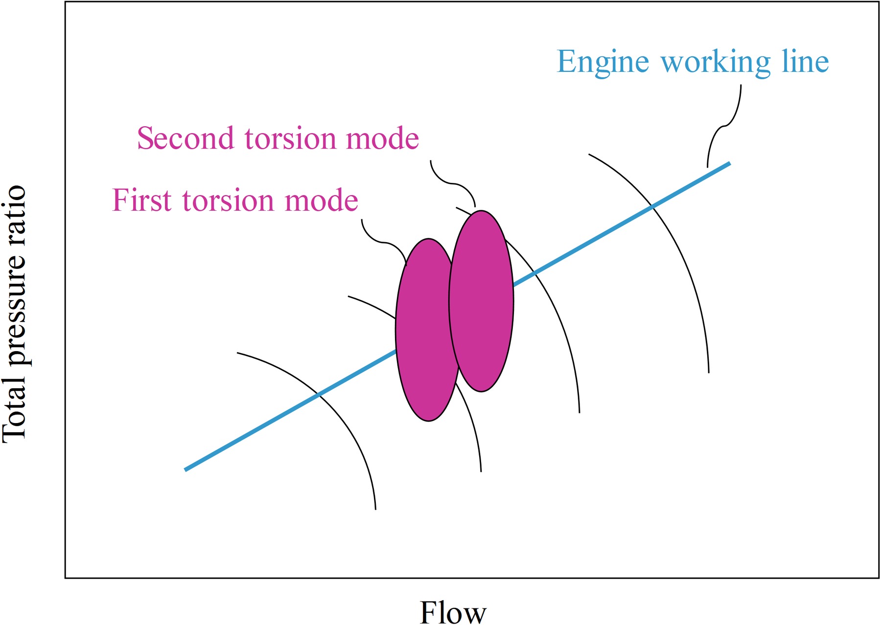
Another serious damage induced by tip clearance flows is the blade nonsynchronous vibrations (NSV) which may cause a premature blade failure. NSV is a fluid dynamic instability that could cause rotor blades vibrating in the first torsion mode (1 T) or the second torsion mode (2 T) or both. Figure 2 gives a representative example of NSV behavior on the compressor map (Kielb et al., 2003). Vo (2010) thought it was the tip clearance backflows below the trailing edge tip induced by RI impinging on the adjacent blade tip that caused NSV. Further, Thomassin et al. (2009, 2011) proposed a novel theory based on the acoustic feedback in the jet core to explain the physical mechanism of NSV, gave a prediction equation to determine the critical rotation speed in which the NSV might occur, and experimentally validated the theory. Following the research of Thomassin, Drolet et al. (2012) supplemented and developed the theory by conducting a series of computational simulations.
Researches on the influence of tip clearance variation on the acoustic noise of compressor have been widely carried out in previous literature, and an understanding has been obtained is that the acoustic noise increases with the increasing tip clearance and decreases with the decreasing tip clearance (Kameier and Neise, 1997). A distinguishing feature of centrifugal compressors is that there are usually two different types of blades, i.e., main blades and splitter blades. Considering the different blade profiles and flow functions of main blades and splitter blades, a question arises, are the roles of the blade tip clearance of main blades and splitter blades the same in the aeroacoustics?
Increasing/decreasing all blade tip clearances at the same time would change the compressor work inputs (Turunen-Saaresti and Jaatinen, 2013). It is unfair to compare the aeroacoustic characteristics between the compressors with different work inputs. In the present work, a comparative experiment was designed including three compressors with different tip clearance configurations. One compressor was acted as a datum with the uniform blade tip clearances, but in the other two compressors, the blade tip clearances of main blades and splitter blades were different for keeping the roughly equivalent work input to the datum. The detailed tip clearance configurations of the three compressors will be shown in the latter part.
Case illustration
There are three cases with different tip clearance configurations in the present work. The datum, termed M0.5S0.5, is a centrifugal compressor with a vaneless diffuser that has 7 main blades and 7 splitter blades, and blade tip clearances of main blades and splitter blades both are 0.5 mm. The detailed compressor parameters are shown in Table 1. Different from the datum, the blade tip clearances of the main blades and the splitter blades are uneven in the other two cases. In one case, termed as M0.6S0.4, the blade tip clearances of the main blades are all 0.6 mm, while those of splitter blades are all 0.4 mm. in the other case, termed as M0.4S0.6, the blade tip clearances of main blades are all 0.4 mm, while those of splitter blades are all 0.6 mm. The blade tip clearance configurations of these three cases are shown in Table 2.
Table 1.
Detailed compressor parameters.
Experiment setup
The experiments were conducted on a turbocharger test rig. The compressor was driven by a turbine whose power came from the hot gas generated in the combustor. The schematic diagram of the experiment rig is shown in Figure 3. A speed transducer of magnetic induction was fixed on the inducer casing, which did not need to chisel an installation hole in the casing and could avoid the flow disturbances caused by the installation of the transducer, to monitor impeller rotation speeds. The total pressure and the total temperature transducers were installed downstream compressor volute outlet for evaluating the compressor performance. Meanwhile, a mass flow transducer was installed in the downstream pipe. Two acoustic transducers, which were fixed on tripods and kept the same height with the compressor inlet pipe, were arranged in two different positions to monitor the far filed acoustic characteristics: the acoustic transducer 1# was located at the compressor inlet and kept a one-meter distance; the acoustic transducer 2# flanked the compressor and also kept a one-meter distance, detailed positions were shown in Figure 3. The sampling frequency of the acoustic transducer was 2.56 × 10⁴ Hz, so the maximum frequency of the noise frequency spectrum could range up to 1.28 × 10⁴ Hz according to the Nyquist theory, which met the requirements of present studies.
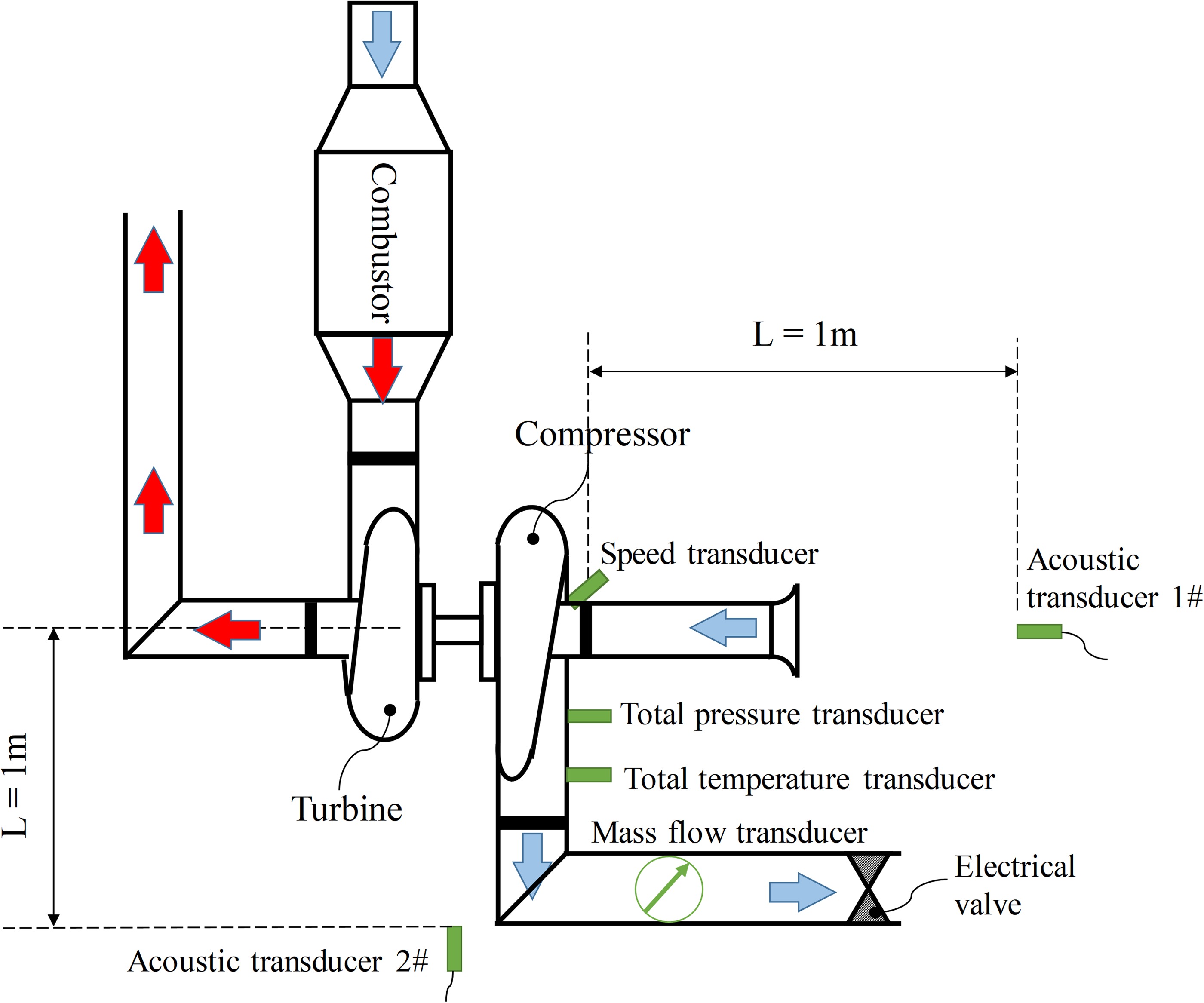
The compressed air flowing into the combustor came from a screw compressor which was in another operation room neighboring to the test room. Both the outflow gas from the turbine and the outflow compressed air from the centrifugal compressor were discharged into the atmosphere outside of the test room. Only the compressor inlet of the whole experiment rig was open in the test room.
The compressor performances on three constant speed lines (5 × 10⁴ rpm, 6 × 10⁴ rpm, and 7 × 10⁴ rpm) were obtained by adjusting the fuel mass flow rate into the combustor and the electrical valve opening degree downstream the compressor, independently. Three representative operation points were selected to collect the far-field acoustics at each constant speed line for every case. The three representative operation points are near the blockage region, the highest-efficiency region, and the flow instability region, respectively. The mass flow rates of the three representative operation points of each case at the same rotation speed keep as the same as possible for good comparisons. The mass flow rates of representative operation points are shown in Table 3.
Result discussion
Compressor performance
The determination of the last stable flow operation point, that is the surge line, was made based on the human hearing by technicians. Although it is not very scientific, it could be accepted in present work in which the surge is not the focus.
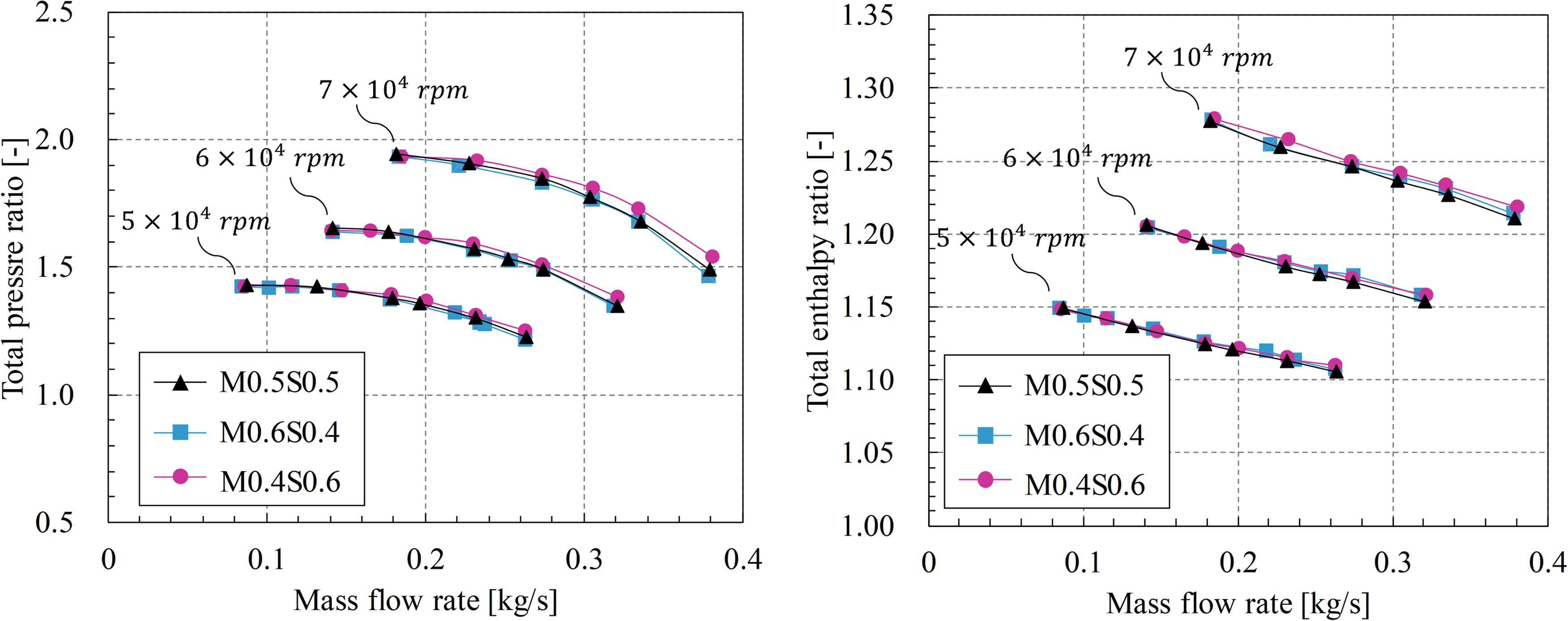
The compressor total pressure ratio and total enthalpy ratio of the three cases were shown in Figure 4. The results showed that the work inputs of cases with uneven blade tip clearances were roughly equivalent to the datum as expected.
Rotating instability
RI is a special flow phenomenon related to the interaction between the main passage flow and the blade tip leakage flow. The blade height of the centrifugal compressor is usually small, which leads to a bigger ratio of blade tip clearance to blade height for the same tip clearance in comparison with the axial compressor, so RI does not only occur near flow instability regions but also in stable flow regions.
There are two important discrete noises that are very easy to be found in the frequency spectrum. One is the blade passing frequency of the compressor (BPF-C), of which the frequency is
where N is the impeller rotation speed (rpm), and mC is the blade number of main blades or splitter blades. mC = 7 in present study. The other one is the blade passing frequency of the turbine (BPF-T), of which the frequency is
where mT is the blade number of the turbine. mT = 10 in present study.
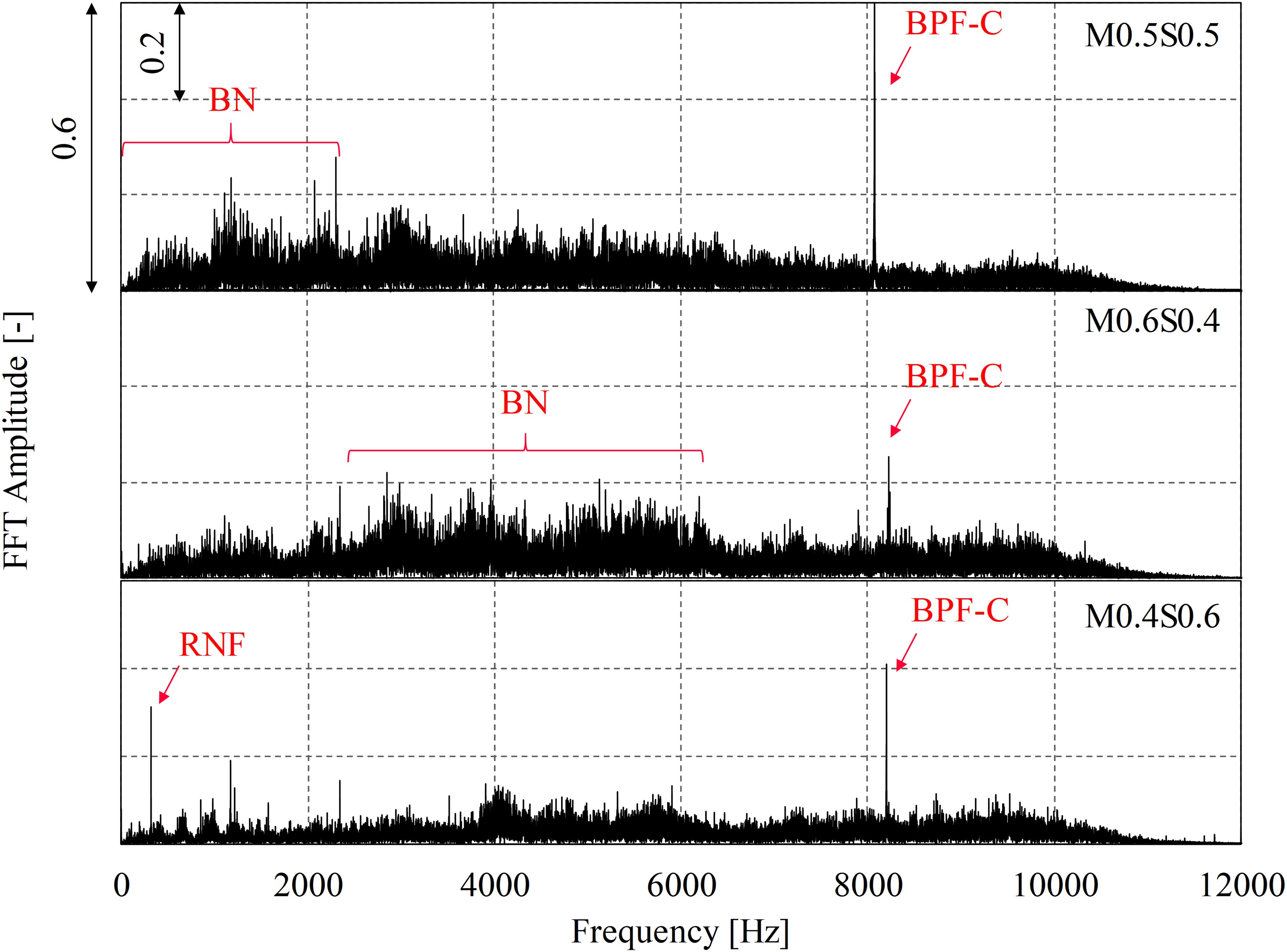
Different from the datum M0.5S0.5, RIs, which could be deduced from the frequency spectrum characteristics as shown in Figure 1, become more obvious in the cases of M0.4S0.6 and M0.6S0.4 at Ф3 when the impeller rotation speed is 5 × 10⁴ rpm and 6 × 10⁴ rpm, as shown in Figures 5 and 6. The RI hump of M0.6S0.4 is mainly induced by the increasing tip clearance of the main blade, of which the amplitudes are significantly higher than those in the other two cases. However, the formation reason of the RI hump of M0.4S0.6 is different from that of M0.6S0.4. There are no apparent variations in the amplitudes of frequencies corresponding to RI between M0.4S0.6 and M0.5S0.5. The emergence of the RI hump in M0.4S0.6 more relies on the decrease of amplitudes of broadband noises (BN) of which the frequencies are below RI. These broadband noises below RI, which are usually explained to be related to tip clearance leakage flows, are suppressed in the case M0.6S0.4 and M0.4S0.6 at the impeller rotation speed of 5 × 10⁴ rpm and 6 × 10⁴ rpm. Especially at 6 × 10⁴ rpm, the suppression of BN is significantly obvious in M0.6S0.4 and M0.4S0.6 comparing with the datum M0.5S0.5, as shown in Figure 6. A reasonable deduction for this phenomenon is that the different blade tip clearance gaps of main blades and splitter blades induce two different types of tip clearance leakage vortexes with incongruous dynamic behaviors, which neutralize each other, so BNs are suppressed. Because the characteristics of blade tip clearance leakage vortexes are also related to the impeller rotation speed except for the tip clearance size, the neutralizing effects between tip clearance leakage vortexes of main blades and splitter blades would change with different rotation speeds.
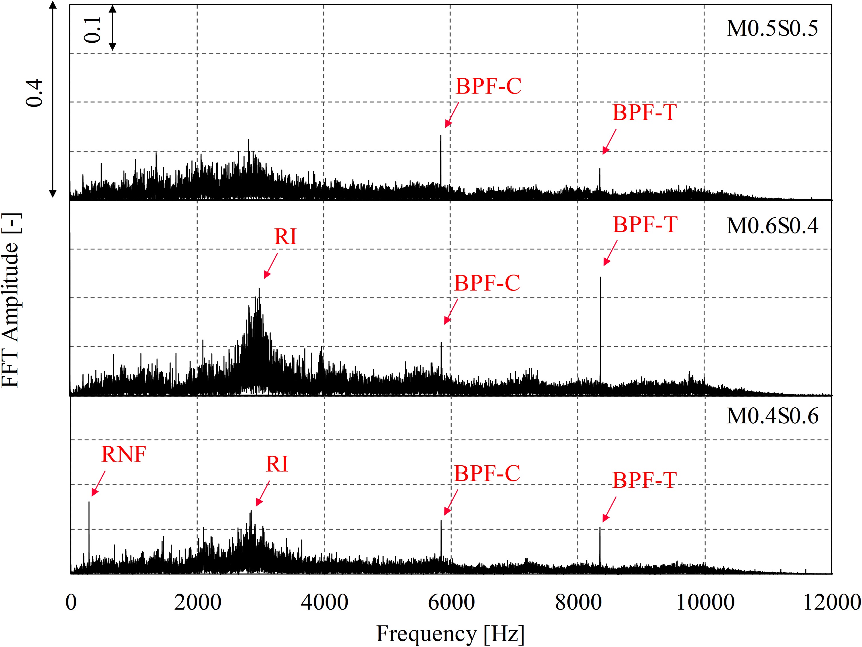
In addition, a tonal noise of which the frequency is around 300 Hz, coming from experiment rig vibrating at rig natural frequency (RNF), can be seen in Figure 5. This tonal noise RNF could also be seen in other operation points and cases, and its frequency is always around 300 Hz, so it should be owed to the experiment rig vibrations rather than other air flows.
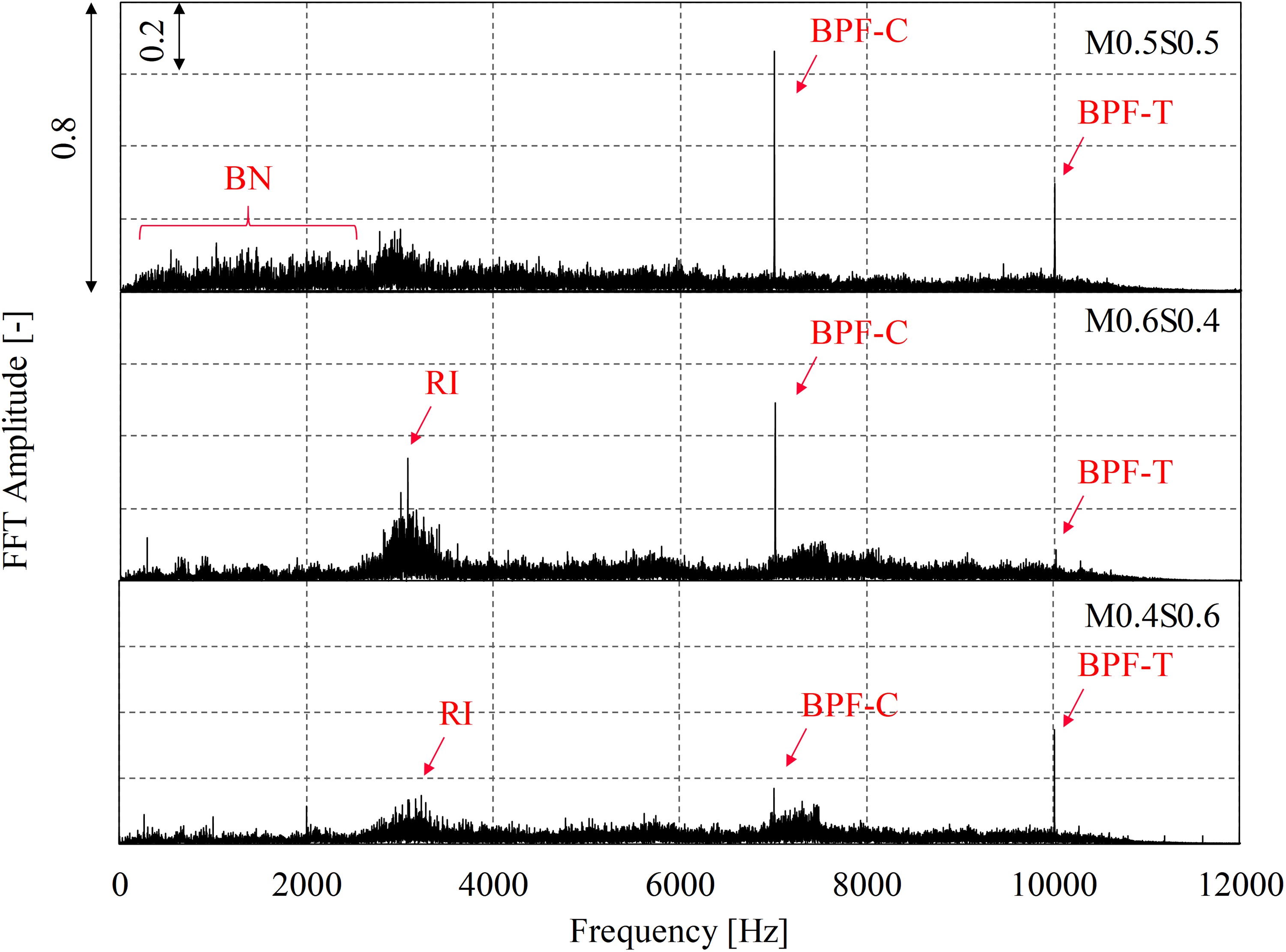
Different from those observed at 5 × 10⁴ rpm and 6 × 10⁴ rpm, there are no RI humps in frequency spectrums in Ф3 at 7 × 10⁴ rpm, as shown in Figure 7. This is due to the flow instability characteristics of centrifugal compressors. When the impeller rotation speed is low, the flow breakdown of centrifugal compressors occurs in the inducer which usually behaves as the rotating stall or RI. However, at higher impeller rotation speeds, the rotating stall or RI occurs in the inducer first which does not lead the compressor to the flow breakdown yet. Then decreasing the mass flow rate further, the flow instabilities in the inducer disappear and shift to the diffuser, meanwhile, the flow breakdown occurs and it usually behaves as the surge. The results of Figure 7 show that the flow instabilities have shifted from the inducer to the diffuser at 7 × 10⁴ rpm. As to BN, similar to the situations at 5 × 10⁴ rpm and 6 × 10⁴ rpm, the BN of M0.4S06 is suppressed significantly in comparison with the case of M0.5S0.5. The suppression of BN is not apparent in M0.6S0.4, but the frequencies of BN peaks shift in comparison with the case of M0.5S0.5. The different characteristics of BN at 5 × 10⁴ rpm, 6 × 10⁴ rpm, and 7 × 10⁴ rpm further indicate that BN belongs to aeroacoustics and is related to the tip clearance leakage flow.
Nonsynchronous vibrations
NSVs have been observed in compressors by many researchers. It is caused by the rotor blade vibration at nonintegral multiples of shaft rotation frequencies, of which the excitation source comes from the blade tip clearance flow unsteadiness. Thomassin et al. (2009) explained the mechanisms of blade tip clearance flow triggering compressor NSV based on the jet core feedback theory, as shown in Figure 8.
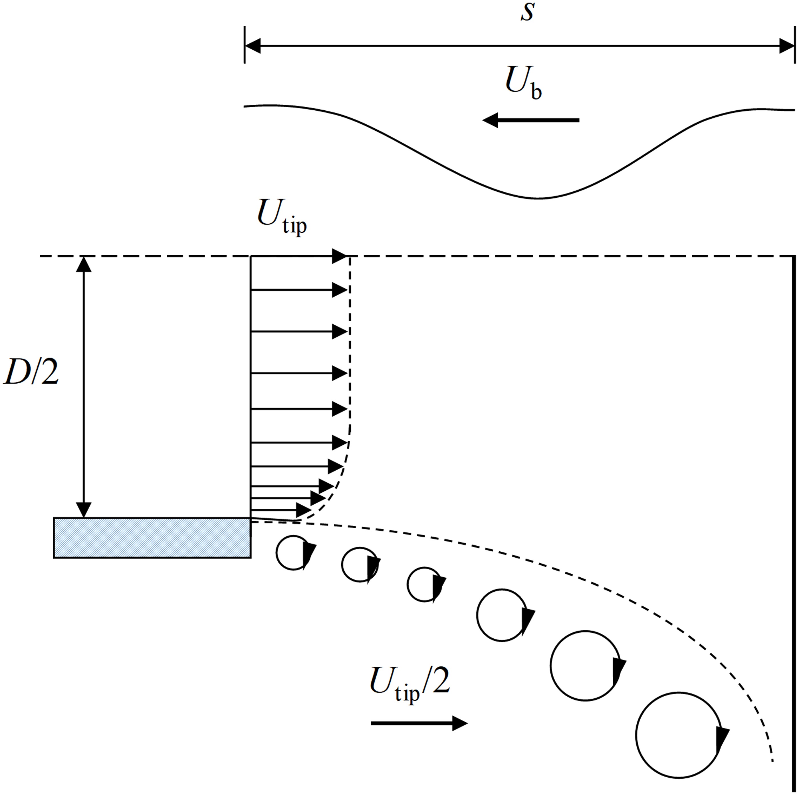
The blade tip clearance leakage flow would produce some small vortical structures through the shear layer, of which the convection speed is around the half of blade tip velocity,
where c is the sound speed.
When the acoustic feedback wave length
where s is the blade pitch, the tip clearance vortical structure formation would be locked onto the blade vibration.
Further, Thomassin et al. proposed a criterion for predicting the critical blade tip velocity
where c is the sound speed, s is the blade pitch, and n is an integer for acoustic feedback wave number which is induced by the blade NSV.
The studies of Thomassin were on axial compressors, so the blade tip velocity
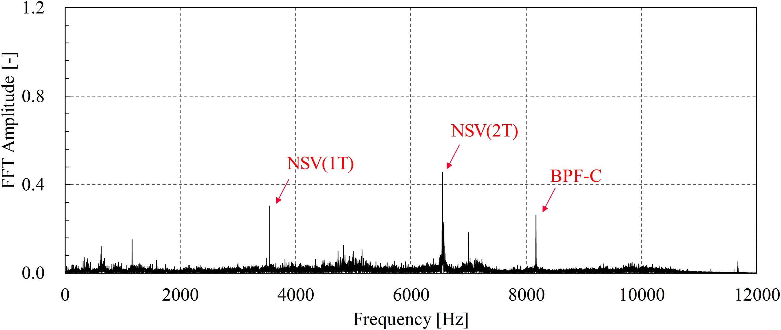
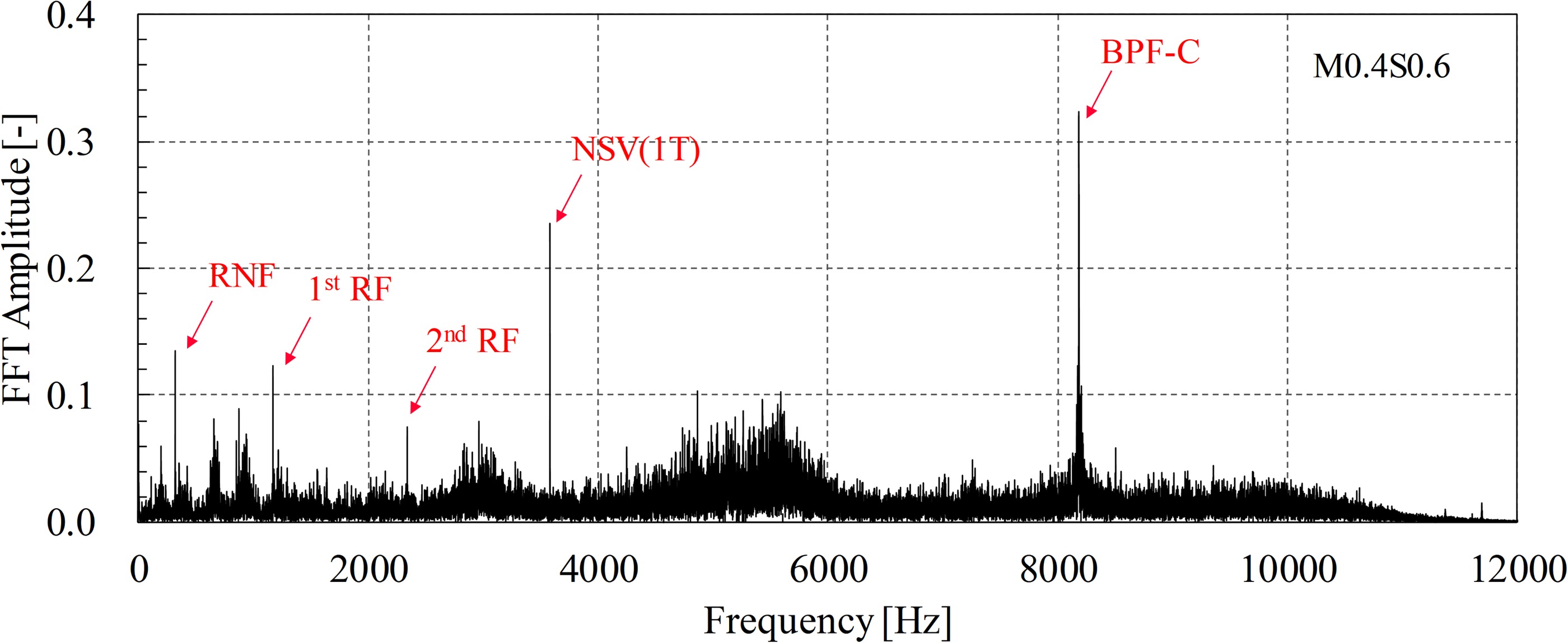
At 7 × 10⁴ rpm Ф1 operation point, an interesting phenomenon worth being noted is that there appear two significant nonsynchronous noises in the case of M0.4S0.6, one frequency around 3,550 Hz, the other around 6,550 Hz, while these nonsynchronous noises are inconspicuous in other cases of M0.5S0.5 and M0.6S0.4, as shown in Figure 9.

According to equation (5), the relationship between the critical blade tip velocity
Figure 10.
Relationship between the critical blade tip velocity ( U tip , c ) ( U tip )

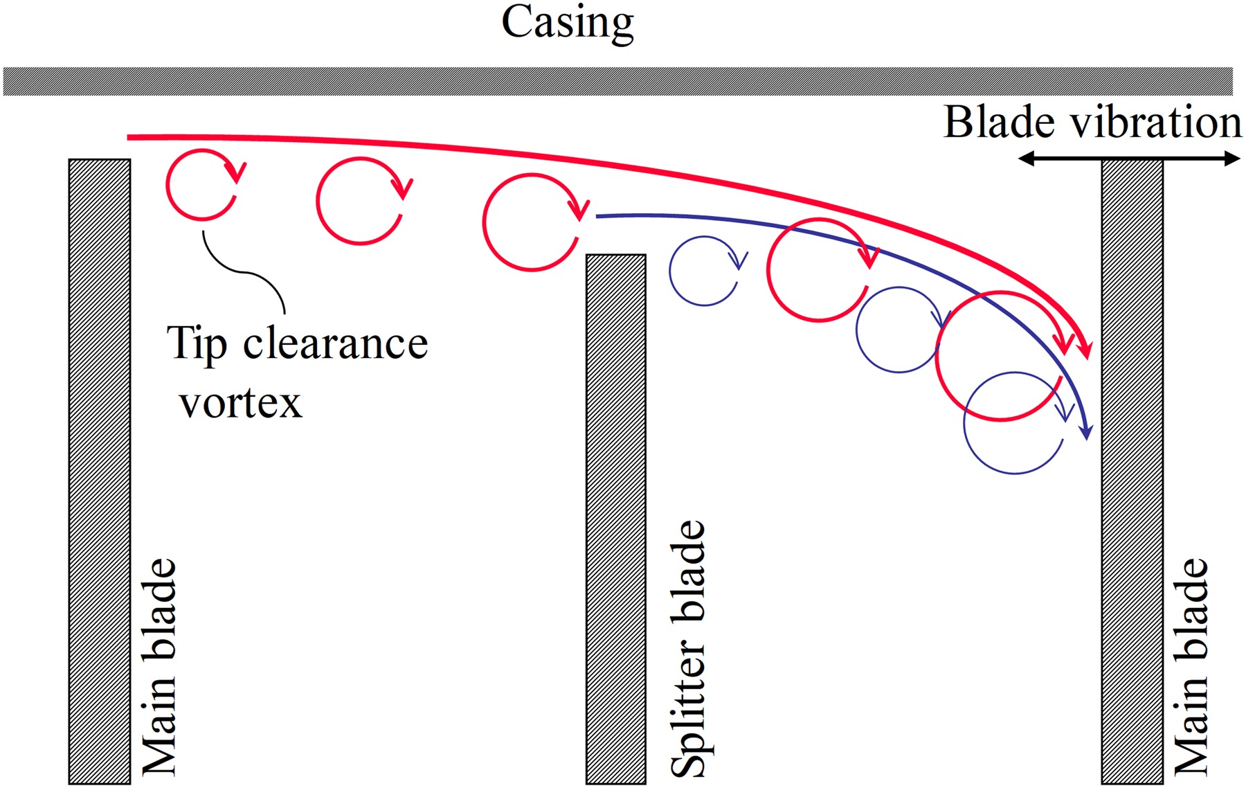
In the case of M0.4S0.6, smaller tip clearances of main blades mean more work inputs and stronger tip clearance leakage flows, meanwhile, the larger tip clearances of splitter blades give an unblocked flow channel for the tip clearance vortexes going through. This results in a combination of tip clearance vortexes of main blades and splitter blades, and a stronger jet flow impingement on the main blade tip. The schematic diagram of this process is shown in Figure 11. This causes the impeller to vibrate in both the first and the second torsional modes.
Figure 11.
Schematic diagram of blade tip clearance vortexes impinging on the blade tip in the case of M0.4S0.6.
Except for the compressor inlet, the NSV (1 T) and NSV (2 T) can also be found in the frequency spectrum of noise collected by acoustic transducer 2# flanking the compressor, as shown in Figure 12.
More operation points at different impeller rotation speeds and mass flow rates are examined for NSV in the case of M0.4S0.6. It is found that there are another two operation points at which the NSVs exist. One is at Ф2 of 7 × 10⁴ rpm, the other is at Ф2 of 6 × 10⁴ rpm, as shown in Figures 13 and 14. In these two operation points, the NSV only occurs at the first torsion vibration mode.
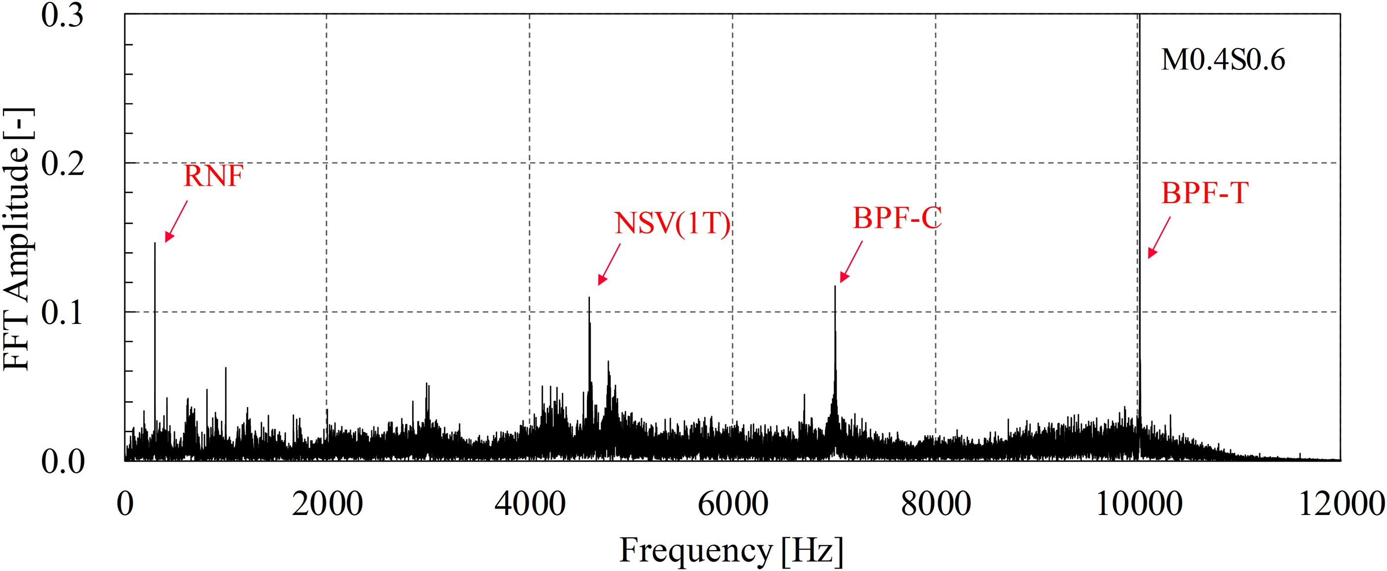
At Ф2 of 7 × 10⁴ rpm, the frequency of NSV is almost the same, around 3,550 Hz. In addition, the noise at the first (1st RF) and the second shaft rotation speed frequencies (2nd RF) could be also seen. However, at Ф2 of 6 × 10⁴ rpm, the frequency of NSV shifts to 4,580 Hz.
At a certain range of impeller rotation speeds, the frequency shift of NSV was also observed in the experiments by Kielb (Kielb et al., 2003), in which the frequency of NSV shifted from 2,600 to 2,661 Hz when the rotation speed decreased from 12,880 to 12,700 rpm. The mechanism of NSV frequency shift is still unknown, which may rely on the computation of fluid dynamics to explore the detailed unsteady flow field.
Conclusion
The blade tip clearance is a crucial factor in the compressor performance and the aeroacoustics. Keeping almost the same work inputs, three different tip clearance configurations with uneven tip clearance gaps of main blades and splitter blades were designed in the present work, and the influences of uneven blade tip clearances on aeroacoustic characteristics of centrifugal compressors were experimentally investigated. Several main conclusions are drawn as follows.
There exists a close relationship between the blade tip clearance flow and NSV. The larger tip clearances of splitter blades and the smaller tip clearances of main blades in M0.4S0.6 make a confluence of tip clearance vortexes coming from main blade tips and splitter blade tips. this forms a strong jet impinging on the main blade tip and induces significant NSVs, of which the main characteristics can be caught by analyzing the frequency spectrum of far-field noises.
Only increasing the tip clearance gaps of either main blades or splitter blades would induce the RI near flow instability regions at low impeller rotation speeds for centrifugal compressors. However, the uneven tip clearance configuration can significantly decrease the broadband noise below BPF, which may be owed to the neutralizing interaction between the tip clearance vortexes coming from main blade tips and splitter blade tips. It may be a new method to control the aeroacoustics of turbomachinery.
Nomenclature
c
sound speed
fb
blade natural frequency
fBPF-C
blade passing frequency of compressor
fBPF-T
blade passing frequency of turbine
mC
blade number of compressor main blades
mT
blade number of turbine
N
impeller rotation speed
s
blade pitch
Ub
speed of acoustic feedback wave
Utip
velocity of blade tip
Utip,c
critical velocity of blade tip
acoustic feedback wave length
Ф
mass flow rate