
Introduction
In the 21st century, Combined Cycle (CC) flexibility and global efficiency are receiving the utmost research attention that is ought to. Moreover, the transition of the energy sector towards an electrical market with high penetration of renewable sources (RES), poses major challenges and opportunities for Original Equipment Manufacturers (OEMs) and utilities (Eser et al., 2017).
The gas turbine (GT) is one of the most important components in a CC power plant and hence, power augmentation technologies concerning this part have gained significant attention. From the power producers' point of view, this is important in using GT generators to provide on-peak power. On the other hand, from the power consumers' perspective who operate GT generators and purchase electricity from electric power companies, power augmentation is important to reduce demand and energy charges of electricity purchased (Yokoyama and Ito, 2004). The research activities for CCs flexibility focus mainly on the GT, aiming to extend the operational envelope of this component, mainly constrained by emissions. For the last decade, the main focus of power augmentation technologies is directed to inlet cooling systems as a cost-effective way to add machine capacity at times when peak power is required for warm and dry operational environments.
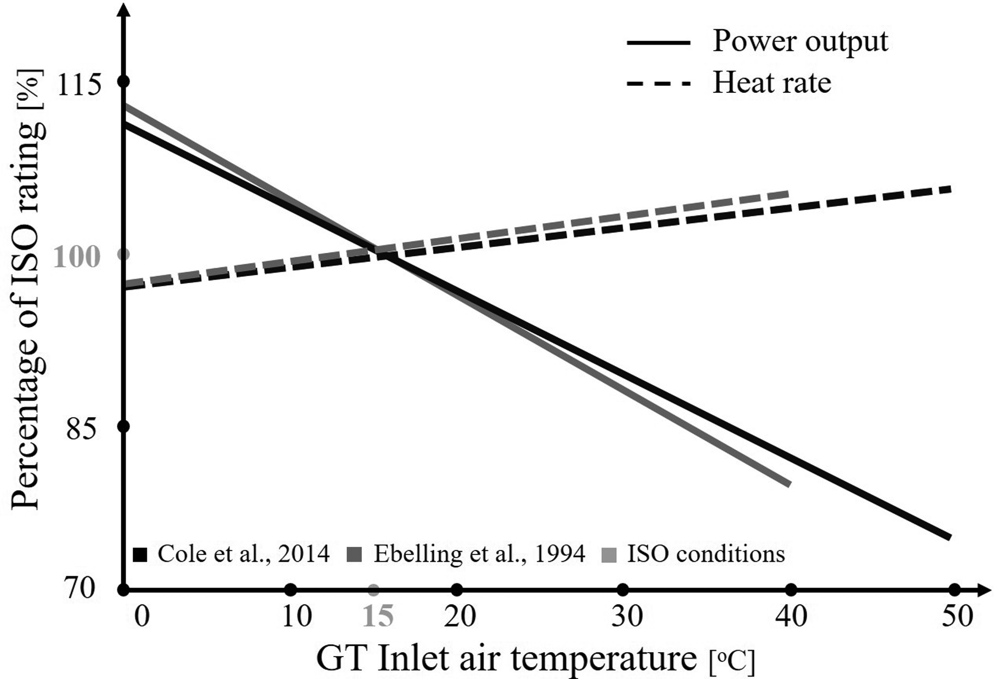
Initially designed to operate at ISO conditions (15°C ambient temperature, 101.32 kPa atmospheric pressure and 60% relative humidity), it is apparent that GTs operate mainly in off-design conditions, making them highly dependent on the ambient conditions. Among the various parameters, the ambient temperature causes the greatest performance variation during operation (Ponce Arrieta and Silva Lora, 2005). Furthermore, it is well known that reducing the air temperature results in higher air density, bearing in mind that the GT operates in a quasi-constant volumetric flow rate. This leads to increased air mass flows and thus, increased power output. Moreover, the mechanical work consumed to compress the denser air is reduced, leading to considerable thermal efficiency increase. The effect of ambient temperature on the power output and heat rate can be observed in Figure 1. The term “heat rate” refers to the amount of thermal energy required to obtain 1 kWh of electricity and is in the form of reverse efficiency, usually applied in power plants. According to the various scientific papers and based on the type of GT used (aeroderivative GTs are more sensitive to ambient conditions compared to heavy duty GTs — Bhargava and Meher-Homji, 2005), a power output decrease of 0.5%–0.9% is observed for every 1°C increase in ambient temperature (Kakaras et al., 2004; Cole et al., 2014).
Having discussed the above and in order to improve the performance of an industrial gas turbine, various available strategies have been studied in existing literature. The two main classifications are (Wang and Chiou, 2004; Bianchi et al., 2010; Gülen, 2017; Winkler et al., 2017):
Of the two power augmenting techniques, the former is concerned herein as a feasible solution to determine the GT inlet conditions. Among the various cooling methods that are described in the following sections, the focus of this work is put on the thermal energy storage (TES) technologies and the way these are utilized to cool the inlet of the GT. The reason for that is twofold. On one hand, as an inlet air cooling method, latent heat thermal energy storage systems (LHTES) based on ice storage have received the most attention in the recent years (Sanaye et al., 2011). Additionally, apart from using solely ice, an interesting application that has emerged in the field of cold storage systems is the use of other phase-change materials (PCM), although this technology requires further development and investigation for a GT inlet air cooling implementation (Cheralathan et al., 2007; Bédécarrats and Strub, 2009). On the other hand, cold thermal energy storage is deemed an appropriate way in balancing the mismatch that occurs on the energy demand and supply.
While viewed as a review paper on the merits of TES in the cooling system of a large-scale gas turbine, it is deemed imperative to initially present all the GT compressor inlet cooling methods. The TES systems are then thoroughly explained followed by a case study section aiming to assess the impact of such systems in the performance of a GT or the CC as a whole. Last but not least, a state-of-the-art section discusses the optimization studies and some contemporary technologies that are currently under development and may potentially lead to further improvement on the aforementioned systems unit sizing and cost.
Gas turbine inlet cooling
As already stated, the reduction of GT inlet temperature leads to power output and energy efficiency increase. Despite there are many different cooling methods, they are subject to the same limitations. First, the GT mechanical characteristics and the electric power generator limitations. These include engine speed limits, mechanical tolerances and maximum heating losses that can be sustained by the armature windings in the alternator.
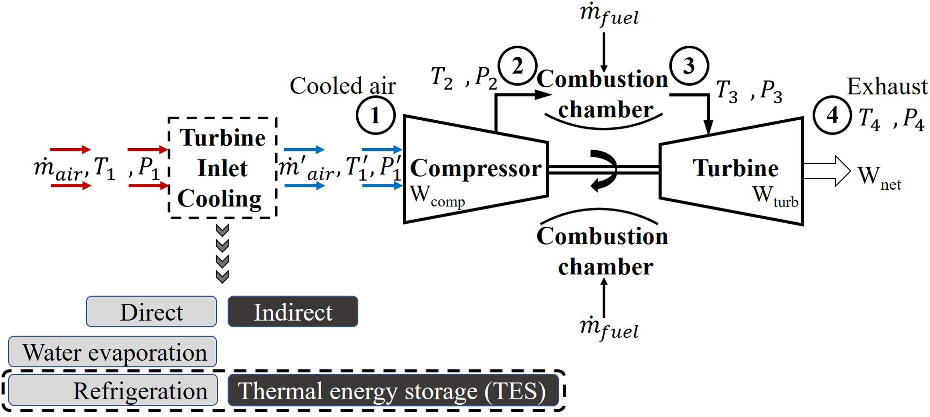
Secondly, icing formation that can occur below a specific temperature, if the saturated inlet air is cooled near the dew point. This imposes a temperature constraint (∼5.5–7.2°C) as ice-crystals may lead to severe erosion and wear of the intake guide vanes (Sigler et al., 2001; Chacartegui et al., 2008). Being aware of the latter, the techniques (Figure 2) used to cool the air entering the GT may be classified into direct and indirect methods.
Direct methods consist of the following segments:
Water evaporation methods (Evaporative cooling, inlet fogging).
Refrigeration methods (Mechanical refrigeration and absorption chilling).
Hybrid and other methods (these mostly are sub-categories or combinations of the two major direct cooling classifications).
Indirect methods include cooling techniques that take advantage of a TES system and are thoroughly described in the following section.
The main characteristics and major advantages and disadvantages of the direct cooling methods are highlighted in Table 1. One general conclusion that can be drawn according to the available scientific literature is that there is no strict rule as to what technology is the best to be applied in each configuration. For example, evaporative cooling method is cost-effective and simple but is limited by the ambient air relative humidity. Mechanical and absorption cooling methods overcome this limitation but either consume electric power for their operation thus imposing parasitic losses or they are limited to refrigerant cooling temperatures. For instance, using an ammonia-water absorption machine may cool the inlet air to lower temperatures than the lithium-bromide technology (Sigler et al., 2001) but the negative effects are that this solution has toxicity related issues.
Table 1.
Design considerations of the GT cooling methods found in the literature.
Al-Ansary et al., 2013; Al-Ibrahim and Varnham, 2010; Alhazmy and Najjar, 2004; Ameri et al., 2007; Ameri and Hejazi, 2004; Baakeem et al., 2018; Bhargava and Meher-Homji, 2005; Boonnasa et al., 2006; Bracco et al., 2007; Chacartegui et al., 2008; Farzaneh-Gord and Deymi-Dashtebayaz, 2011; Kakaras et al., 2006; Kwon et al., 2016; Kim and Ro, 2000; Meher-Homji and Mee, 2000; Palestra et al., 2008; Sigler et al., 2001.
The various studies underline that the choice of each application is a multi-parametric task that depends on the climatic and economic conditions that dominate along with the power requirements that characterize the respective network (De Lucia et al., 1996). The two main points that are deemed as viable solutions for the future and require further investigation are a decoupling of the refrigeration system from the actual peak times when prices are high and an advanced control system for real-time supervision aiming for optimal solutions and overall flexibility enhancement. One such decoupling technology is enabled by the use of a thermal energy storage system, to lower electricity consumption during peak hours. Decoupling necessitates the use of an integrated inlet conditioning system that will allow for the full exploitation of the power plant installed capacity. In contrast to the aforementioned refrigeration techniques, the addition of TES produces only minimal parasitic losses during the time of maximum energy requirements.
Of the various TES systems, latent heat TES have the strongest potential towards an integrated inlet conditioning system regarding GT compressor inlet cooling. Their high energy density and compactness along with the quasi-constant melting and freezing temperatures make them uniquely suitable for such applications, where stabilization of the GT air inlet temperature is important. The effect of the storage type on the GT cooling is studied in the following.
Thermal energy storage
When it comes to large-scale power production systems, especially those that include electricity generated from renewable sources, several types of storage technologies can be developed and implemented (Ibrahim et al., 2008). One type of storage systems is the thermal energy storage (TES) that can be combined with the abovementioned direct cooling methods and constitute an indirect cooling mechanism. TES appears to be the most suitable method for correcting the discrepancy that usually occurs between the supply and demand of energy (Dincer and Rosen, 2010). Despite that the benefits are not evident since they are not immediate in many cases, the potential energy savings and climate change mitigation combined with their simplicity make it a favorably promising technology for the future (Cabeza et al., 2015). One of the innovative performance enhancement techniques integrates a TES tank with the GT compressor inlet cooling system to reduce on-peak electricity consumption. This is achieved by charging the cold TES at off-peak hours (during the night) while electricity prices are lower and discharging it during peak hours to increase GT power output when prices are high (Bédécarrats and Strub, 2009; Sanaye et al., 2011). Primarily, two types of TES systems can be used for inlet cooling of a gas turbine:
Apart from solely considering the thermodynamics and performance, the economic outlook of such systems is also an essential parameter in selecting the most suitable technology.
Inlet cooling with sensible heat TES
The first classification of cold thermal storage is the system that utilizes the sensible heat that is stored (or released) during the charging/discharging of the storage media. Sensible heat is the amount of heat released/absorbed due to a temperature change in the storage material. Phase change does not take place in this type of storage systems. The most commonly used storage medium is the water. However, other aqueous fluid solutions can be employed in the following sensible heat storage technologies.
Stratified chilled water
This is a conventional method of sensible TES. The amount of stored energy depends on the temperature difference between the stratified layers of water. These layers are formed in a vertical orientation inside the storage tank and are scaled temperature zones based on the water density. The stratification inside the tank defines the cooling capacity of the system as it depends on the temperature differential across the tank height. A good design of stratified tank consists of a thermocline range of approximately 0.3–1.0 m which depends on the diffuser design and the time that the water remains stored inside the TES. The tank is charged with water at 4–6°C. During discharge, the cold-water flows reversely from the tank to the system, employs cooling, and returns to the top layers of the tank in a higher temperature at low flow rates, in order to minimize the mixing of the layers (Hasnain, 1998).
The simplicity and proven reliability combined with the relatively low cost make it an easily applicable and well-established technology. Additionally, it provides greater performance augmentation as compared to the water evaporation methods. One of its major drawbacks is the low storage capacity per unit volume. This effect is magnified if the requirement in temperature difference between the cold and warm water is small (Palestra et al., 2008). Hasnain (1998) emphasizes that statement, proving that each cubic meter can deliver only 5.8 kWh of cooling if the requirement in temperature rise is 5°C. Another disadvantage of this technology is that it only provides limited hours of cooling per day which is a characteristic of all thermal energy storage systems.
Other aqueous stratified solutions
In order to further reduce the inlet air temperature at the lowest possible solution to avoid icing, water is replaced with other fluids such as brines, calcium chloride (CaCl2) and glycol (Quinnell et al., 2010). Despite their benefits such as operating below the freezing point of water, these solutions are expensive or tend to be corrosive and require specific treatment to avoid these events.
Inlet cooling with latent heat TES
As already mentioned earlier, LHTES have the strongest potential towards an integrated and decoupled operation of the GT inlet conditioning system. This storage type takes advantage of the latent heat that is exchanged whenever a storage material changes its state. Unlike the sensible heat TES, this method provides higher energy density with a smaller temperature difference during charging and discharging. Additionally, it requires a reduced installation area.
Systems such as ice-on-tubes, ice harvesters, ice slurries, and encapsulated ice (or various other PCMs) are some of the identified LHTES that have received the most attention in the recent years due to the benefits that emerge from material phase change in these applications (Cheralathan et al., 2007). Normally, the LHTES is classified as either a static or a dynamic system (Saito, 2002). When referring to static systems, a layer of ice is formed on tubes or plates which are submerged in a tank of water. This layer increases the thermal resistance between the cooling surface and the solid-liquid interface, thus leading to a decrease in the system performance. On the other hand, this problem is avoided in dynamic storage systems where the layers of ice (or in general the solid form of other materials) is systematically or continuously removed. However, when using water as the phase change material in such systems, icing is not desirable after a specific limit — that is, the formation of ice on the outside of vertical evaporator plates. This necessitates the use of external forces to remove the ice and hence, leads to system efficiency losses. This is one of the reasons why studying different materials provides a strong motivation in this area.
Static systems include ice-on-tube, glycol-water (or ethylene-glycol-water) heat exchangers inside ice tanks and encapsulated storage systems. The dynamic systems include ice harvesters and ice slurries, or slurries composed of different materials (Hasnain, 1998). Apparently, these configurations are valid for other PCMs as well, a description of which is given later in this work.
Ice-on-tube
In this configuration, a TES tank is filled with a number of metallic (aluminum, copper, steel) or plastic tubes usually placed in a horizontal orientation either in parallel or in a spiral/helical coil configuration as shown in Figure 3a. The tubes are surrounded by water and a heat transfer fluid (HTF), usually brine that flows through them. As the cold HTF flows through the tubes, ice is formed perimetrically. Whenever the tank is required to supply cooling, the warmer HTF flows through the tank leading to ice melting.

Glycol-water submerged heat exchanger
In this solution (Figure 3b), heat is transferred to the HTF through the heat exchanger from the storage material during the charging process and is then discharged when cooling is required by the system, respectively. Research interest to further enhancing the thermal performance of such systems has led to several alternatives such as the incorporation of fins either orthogonal or cylindrical (Chiu and Martin, 2012).
Encapsulated storage systems
The research of encapsulated storage technologies has received increasing attention over the past years. The main advantages of this method are the increase of heat transfer they provide and that they prevent mixing with the HTF (Bédécarrats et al., 1996). Various studies have been conducted to analyse the thermal behaviour of these systems (Felix Regin et al., 2009). The design and the size of encapsulated storage determines the heat transfer surface and thus, the thermal performance of the system (Figure 3c).
Ice harvester
This option uses the solid pieces of ice which are formed on the external cold surfaces of evaporators. As a result, solid slabs of ice are formed on the flat evaporator plates. At the time when a certain thickness is reached, the ice is harvested by heating the evaporator and allowing the ice slabs to fall by gravity into a storage tank below (Al Bassam and Al Said, 2001). The heat required by the harvesting process is accomplished by using the hot refrigerant gas from the chiller compressor (Palestra et al., 2008).
Phase change slurries
This dynamic type of storage is also a technology with high potential as it may lead to higher thermal power. In this method, direct contact between the HTF and the storage material (ice or other PCM) is achieved by forming an emulsification with increased thermal storage and heat transfer capacity. This solution also shown in Figure 3d is desirable when aiming for high thermal power. However, it remains a rather new and costly technology which also inheres the risk of system fouling to pipes, heat exchangers and pumps. Regarding ice slurries, brine is considered to be the continuous phase while ice crystals consist the dispersed phase. Mouneer et al. (2010) have reported six types of ice slurry production which include mechanical scraping, fluidized bed, direct contact or direct injection, vacuum freezing, oscillatory moving cooled wall and supercooling methods. With respect to other PCM slurries, the HTF is the continuous and the PCM the dispersed phase (Youssef, 2013).
Phase change materials (PCM) in cold TES
The PCMs are organic, inorganic and eutectic materials. The organic PCMs are carbon-based compounds and can be generally classified as paraffin and non-paraffin materials. Inorganic PCMs are classified into metallic and hydrated salts while eutectic PCMs are combinations of the two former categories with their main purpose being to achieve a desirable melting point. A thorough analysis of such materials can be found in the study of Veerakumar and Sreekumar (2016).
The major advantages of the organic PCMs are their non-corrosive nature with metals, the almost negligible supercooling properties, the high latent heat and recyclability. Their drawbacks consist of a low thermal conductivity, large volumetric change during phase change process and flammability, which, in the case of power production facilities is of utmost importance. As a result, they usually require specific treatment as encapsulation which results in higher capital and other variable costs (for example capsule replacement).
On the other hand, inorganic compounds such as salt hydrates and composites have much higher latent heat per unit volume, higher thermal conductivity, lower cost, are recyclable and non-flammable. Their corrosive nature with metals reduces the life of the system and increases the overall costs of the system (Cabeza, 2015).
Focusing on each specific application of the TES system, there are conflicting requirements that must be investigated prior to the final material selection. For this reason, there are several quality criteria that need to be met and are based on the dynamics of melting or solidification of PCM. The main requirements are the (i) stored energy or thermal inertia, (ii) the discharge power and (iii) the discharge time. These must be sought to achieve high efficiency, robustness and viability of the products (Vitorino et al., 2016).
Discussion
As described so far, both TES systems have advantages and disadvantages. However, LHTES appears as the technology with improvement potential, especially if other PCMs are used, instead of ice. Compared to the sensible heat storage technologies its main superiorities are:
Lower space requirements and larger cooling capacities providing increased energy density.
Lower thermal losses due to smaller TES tanks which comprise of smaller surface areas.
Potential recovery of thermal energy in quasi-constant temperature.
Ability to store significantly larger amounts of energy in cases where the temperature difference between the heat source and heat sink is small.
Storing of energy at a better efficiency during low-priced off-peak periods. The ratio of the useful cooling latent heat stored to the useful sensible heat is much higher (4–7 times). This reduces the size of the PCM-based TES as compared to the respective sensible heat TES system (Cheralathan et al., 2007).
Stratification requirement is eliminated.
Lower cost of maintenance if encapsulated systems are considered as it facilitates the removal of damaged capsules.
Allowance for an overall downsizing of the system with reduced costs of pumping and air distribution (linked to the lowest possible storage temperatures).
As far as the PCM is concerned, the main material that is used in the literature is water. Its advantages are the durability, high latent heat of freezing, cost-effectiveness and zero environmental impact. However, the occurrence of supercooling and incongruent freezing and melting requires the use of additives to eliminate such phenomena. Supercooling is not desirable in such systems as the temperature of PCMs goes beyond the nominal phase change temperature, thus leading to inability in fully storing heat and additionally, makes it harder for the control systems to adapt as they operate in certain temperature margins.
This leads to the need for further research about materials, to limit the shortcomings that emerge from the use of ice. The literature involving the performance of traditional GT cooling techniques (such as chillers) with storage systems consisting of innovative PCMs is rare. Along with the need for solely studying the materials as an individual parameter, further development and investigations are required when combined with the GT inlet cooling implementation (Barigozzi et al., 2011). All in all, to achieve high efficiencies with TES for the various applications, it is important to consider the system's thermophysical, environmental and economic characteristics (Dincer and Rosen, 2010).
Case studies
The next step after scrutinizing through the available GT cooling methods and the thermal energy storage systems is to provide results based on prior studies that are reported in existing power plants, globally (Figure 4). The cases considered include nearly all of the cooling methods as they have been presented previously in this work. The target is to draw conclusions by evaluating the change in the system performance with the varying operating conditions.
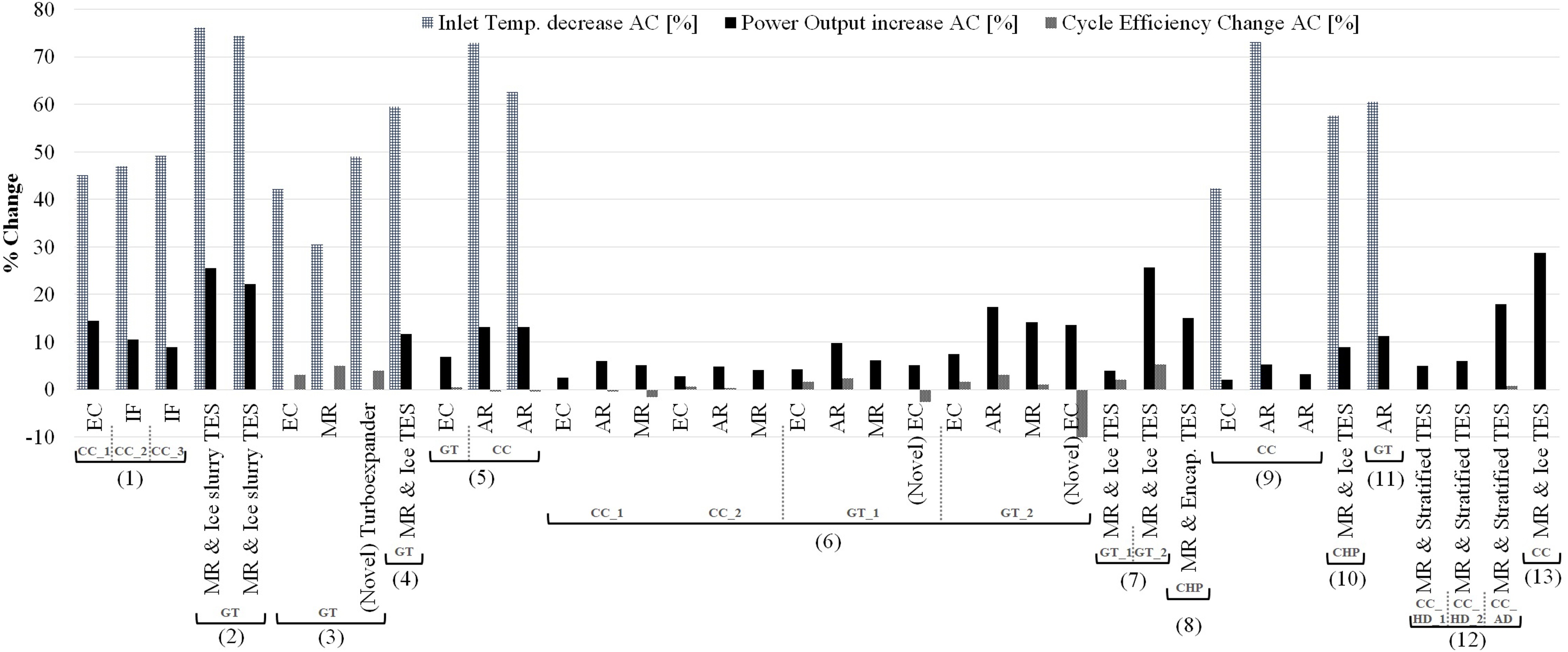
Table 2 includes the corresponding characteristics (ambient conditions and rated power output) of the selected power plants. The results are based on a total of thirteen case studies which are based on calculations performed for existing, simple gas-turbine (GT) or combined cycle (CC) power plants with rated power varying from 1MWel to approximately 400MWel. The indexes used in some GT or CC plants represent a different type of engine used in the corresponding study. Otherwise (no index is used), all cooling methods are applied onto the same system. The criterion chosen for the reference setting of the cumulative graph is the incremental relative humidity (RH). Therefore, the case studies considered first are characterized by hot and dry climate. As the results unwrap, the analysis progresses to humid conditions. Emphasis is put on considering the impact of the selected cooling method on the performance of the gas turbine and the efficiency of the overall cycle if this is provided in each corresponding work. The ambient temperature indicated in the case studies represents either the maximum value or the average temperature distribution of the site location.
Table 2.
Rated power output and ambient conditions of the investigated power plants.
| (1)Ameri et al. (2007) | Location: Western Asia | (7)Sanaye et al. (2011) | Location: Western Asia |
|---|---|---|---|
| Rated Power Output: | Ambient Conditions: | Rated Power Output: | Ambient Conditions: |
| - CC_1: 99.3 MWel | - RH_1: 8.2%, Temp: 38°C | - GT_1: 25 MWel | - RH: 50%, Aver. Temp: 25°C |
| - CC_2: 98.0 MWel | - RH_2: 11%, Temp: 35°C | - GT_2: 100 MWel | |
| - CC_3: 100.0 MWel | - RH_3: 16%, Temp: 32°C | ||
| (2)Al Bassam and Al Said (2001) | Location: Western Asia | (8)Bédécarrats and Strub (2009) | Location: Southern Asia |
| - Rated Power Output: | Ambient Conditions: | Rated Power Output: | Ambient Conditions: |
| - GT: 342.0 MWel | - RH_1: 10%, Temp: 44°C | - CHP: 1.0 MWel | - RH: 60%, Aver. Temp: 32°C |
| - RH_2: 10%, Temp: 39°C | |||
| (3)Farzaneh-Gord and Deymi-Dashtebayaz (2011) | Location: Western Asia | (9)Gareta et al. (2004) | Location: Southern Europe |
| Rated Power Output: | Ambient Conditions: | Rated Power Output: | Ambient Conditions: |
| - GT: 7.5 MWel | - RH_1: 20%, Temp: 43.2°C | - CC: 395.0 MWel | - RH: 65%, Aver. Temp: 26°C |
| (4)Shirazi et al. (2014) | Location: Western Asia | (10)Yokoyama and Ito (2004) | Location: Eastern Asia |
| Rated Power Output: | Ambient Conditions: | Rated Power Output: | Ambient Conditions: |
| - GT: 62.3 MWel | - RH_1: 30%, Temp: 37°C | - CHP: 5.72 MWel | - RH: 65%, Aver. Temp: 16.5°C |
| (5)Kakaras et al. (2004) | Location: Southern Europe | (11)Ameri and Hejazi (2004) | Location: Western Asia |
| Rated Power Output: | Ambient Conditions: | Rated Power Output: | Ambient Conditions: |
| - GT: 4.33 MWel | - RH_1: 45%, Temp: 40°C | - GT: 16.6 MWel | - RH: 70%, Temp: 38°C |
| - CC: 57.0 MWel | - RH_1: 45%, Temp: 40°C | (12)Barigozzi et al. (2011) | Location: Southern Europe |
| - RH_2: 45%, Temp: ≤18.5°C | Rated Power Output: | Ambient Conditions: | |
| (6)Kakaras et al. (2006) | Location: Southern Europe | - CC_HD_1: 127.0 MWel | |
| Rated Power Output: | Ambient Conditions: | - CC_HD_2: 127.0 | - RH: 70%, Aver. Temp: 18°C |
| - CC_1: 560.0 MWel | - CC AD: 111.0 MWel | ||
| - CC_2: 380.0 MWel | - RH: 50%, Aver. Temp: 26°C | (13)Ebelling et al. (1994) | Location: Southern USA |
| - GT_1: 21.3 MWel | Rated Power Output: | Ambient Conditions: | |
| - GT_2: 31.5 MWel | - CC: 285.0 MWel | - RH: 70%, Temp: - |
As far as the results are concerned, it is initially observed that the power augmentation in all case studies varies from 2% to 30% based on the site climatological conditions, the method employed and the size of the plant. On the other hand, the effect can sometimes be adverse with regard to the efficiency of the power plant as a whole. The cases where negative values of efficiency occur are mainly observed whenever refrigeration methods (MR, AR) are employed in CC power plants or novel EC techniques are applied in simple GT plants. The novel EC technique indicated in the sixth (6) case study corresponds to the utilization of an electrically driven fan to pre-compress the inlet air which is then cooled by the EC. A conclusion that can be drawn is that despite the performance improvement of the GT, the implementation of inlet cooling can have a negative effect in the overall combined cycle efficiency. As the turbine outlet temperature is decreased a net reduction in the overall power output is observed due to less energy recovery from the steam turbine.
Moreover, another conclusion is that the EC method is not very effective in areas of humid climate. This is interpreted due to the low power augmentation and its rare application in such areas as compared to the refrigeration methods.
Furthermore, for what concerns the type of GT used, aeroderivative machines have better performance improvement as compared to heavy duty engines. This is shown in case study (12) where the third studied engine corresponds to a high-performance aero-derivative engine that is highly sensitive to the inlet air temperature variation.
As far as TES are considered, the integration of a cooling method with TES allows the designer to select a lower capacity GT. Based on the results of Figure 4, the potential of using a refrigeration chiller with TES leads to notable output power improvement (more than 10%) compared to other methods for power plants with rated power up to 100MWel. TES systems are mostly applied to such applications whereas literature of larger capacity power plants employing LHTES is scarce. The works of Al Bassam and Al Said (2001) and Ebelling et al. (1994) showcase the increase in power output, after employing inlet cooling with TES. It is at this point where it can be understood the necessity to also consider economical aspects in each study so as to evaluate if the investment of adding a TES system is feasible.
Having discussed the above, the available economics described in each of the aforementioned case studies are presented (Table 3). These are costs which correspond to the cooling methods employed and either include capital and investment costs for the selected method or incremental cost of electricity generation per increased MWh. As it would have been misleading to only include one currency (e.g. Euro) for each type of economic result, the results are kept as they are presented in each study. The numbers indicated refer to the power plants described so far.
Table 3.
Economics of the cooling method employed in each studied power plant.
The economic feasibility of the EC method is demonstrated at this point due to the low investment costs as compared to refrigeration methods. However, even that IF has the lowest investment costs, specific attention must be given as it may lead to erosion of the compressor blades which at the end may lead to unbearable cost compared to the investment costs of this technology. Furthermore, according to the available literature, the EC is more appropriate to hot and dry locations. However, the water scarcity in such areas poses a significant constraint. Water is very expensive and valuable. Thus, more expensive refrigeration methods are required which highly increase the complexity and the capital cost of the system. Therefore, the installed cost of the cooling system in terms of cost per incremental power (ICOE) increase requires site-specific investigation. Based on the work of Kakaras et al. (2006) and in terms of ICOE, the EC method has the lowest cost and payback period, followed by the absorption chiller.
If a different strategy is sought combining higher power and flexibility enhancement, TES can become the most thermo-economically appropriate solution. The decoupled nature of this technology provides the ability to be used in the system whenever deemed necessary through advanced controlling systems. A conclusion that can be extracted from Table 3 is that the integration of TES is comparable to the other methods concerning its economic aspect. The higher payback periods may be associated to the highest capital costs which are not available in the current studies. Moreover, if combined with the ability to exploit the stored energy during peak-hours it can result in a cost-effective way to improve both GT and overall cycle performance.
Based on the holistic approach of this section and the research in the available literature, it is found that the choice of each inlet cooling system depends on the location and the investment. Consequently, there is a need for combined technologies and advanced controls requiring optimization of such complex systems.
State-of-the-art
Optimization of inlet cooling systems with TES
The aforementioned systems have a multi-parametric behaviour which leads to the need of optimization through various algorithms. On one hand, the performance and environmental requirements such as efficiency and emissions that need to abide by new legislative frameworks. On the other hand, parameters that involve the economics of the system such as capital investment, maintenance expenses and operational costs.
Adding a TES in the GT inlet cooling system provides decoupling from the system, allowing to store energy during off-peak hours and make use of it whenever is required from the system. This decoupling provides extra degrees of freedom when managing power generation or consumption. For this reason, optimization algorithms are employed to find maximum/minimum values of the variables of the customized objective function. In this manner, constraints can be also considered.
The literature that focuses on time-dependent optimization problems is limited. One of the algorithms used includes sequential quadratic programming. Cole et al. (2014) considered a nonlinear model with capacity as a function of temperature, energy input ratio as a function of temperature and part load ratio and additional elements or constraints.
In another work (Sanaye et al., 2011), the authors employed two objective functions. The first one included capital and operational costs while the second added an exergy destruction cost rate. Moreover, Sanaye and Shirazi (2013) analysed an ice TES system model, from energy, exergy, economic and environmental aspects by applying multi-optimization techniques.
Furthermore, a mixed-integer linear programming problem is employed to determine the capacities of the equipment and maximum demands of utilities, based on operational strategies for seasonal and hourly changes in energy demands (Yokoyama and Ito, 2004). Palestra et al. (2008) developed a code in MATLAB to model and analyse the performance of the whole plant. They found that the economics of the inlet cooling system depend on the design parameters. Optimization of the problem utilizing various parameters led to lower installation costs and increased profitability. Another example of optimization (Shirazi et al., 2014) considered the two conflicting aspects in such topics. These are the thermodynamics and the economics of the application. Hence, a multi-objective genetic algorithm was employed to obtain optimal design parameters. The advantage of this method is the simultaneous processing of any of the conflicting objectives, also including constraints.
Based on the ongoing studies and the works that are available in the literature, it is emphasized that the dynamical behaviour is necessary for the development of a well-designed storage that will be adapted to satisfy a specific cooling demand.
Driving towards the future
Apart from the emerging potential for advanced optimization of the systems presented herein, there is also the opportunity of advanced supervising controllers which will be able to generate the dynamic values based on the required electrical and thermal loads. The roadmap for the future indicates that decoupled components (such as TES for inlet cooling) combined with advanced control systems will provide benefits when considering the overall system efficiency. Innovative controls will allow for integrated inlet conditioning systems that will have the possibility to make use of each component whenever is needed and according to the economic profitability. Additionally, such systems will allow for the simultaneous studying of the inlet heating to overcome the limitation imposed by the icing formation.
Last but not least, the integration of TES with heat pumps can lead to utilizing unexploited sources of energy in power plants as it also appears in recent patents (Motakef and Feher, 2016). Additionally, an innovative layout is studied within the PUMP-HEAT project (www.pumpheat.eu) which is a Horizon 2020 European project. In this layout, an innovative inlet conditioning system combines heat pumps with TES to provide both cooling and heating at the intake of the GT according to the operating conditions. The cooling condition is applied when power augmentation is needed during high electricity price periods. Inlet heating is applied to reduce Minimum Environmental Load during off-peak periods aiming to reduce fuel consumption and avoid daily start-ups.
Concluding remarks
This article consists of a review study of the gas turbine inlet cooling mechanisms. Its focus is put on the use of thermal energy storage systems (TES) motivated by their potential of augmenting the GT power output and balancing the mismatch between energy demand and supply. Further improvement capabilities underlie in such systems if innovative phase change materials are employed. The conclusions than can be drawn from this review work are the following:
General conclusions:
There is no strict rule as to what cooling technology is the best to be applied in each configuration. The selection of each method depends on climatic and economic conditions combined with the power requirements of the respective network.
TES are considered viable solutions for future energy production applications, due to decoupling of the refrigeration system from peak times. Decoupling necessitates the use of an integrated conditioning system through advanced controls, for the full exploitation of the power plant installed capacity.
Latent heat TES have the strongest potential towards integrated inlet conditioning systems, due to their high energy density and compactness (compared to sensible heat TES) with the quasi-constant phase change temperatures, making them uniquely suitable for such applications where stabilization of GT air inlet temperature is important.
The literature of TES in power production applications utilizing PCMs other than ice is limited. New PCMs can provide lower space requirements, larger cooling capacities and reduced size of the overall system with potentially feasible cost.
Technical conclusions:
Power augmentation through GT inlet cooling varies from 2% to 30% based on the site climatological conditions, the method employed and the size of the power plant.
The implementation of inlet cooling can have a negative effect in the overall combined cycle efficiency despite the performance improvement of the GT.
Adding a TES leads to more than 10% power augmentation. Yet expensive, there is still high room for improvement in these technologies, if different materials are examined in power production applications.
Nomenclature
AC
After Cooling
AD
Aeroderivative
AR
Absorption Refrigeration
CC
Combined Cycle
CHP
Combined Heat and Power
EC
Evaporative Cooling
HD
Heavy Duty
HEX
Heat Exchanger
HTF
Heat Transfer Fluid
ICOE
Incremental Cost of Electricity
IF
Inlet Fogging
IRR
Internal Rate of Return
ISO
International Organization for Standardization
LHTES
Latent Heat Thermal Energy Storage
MR
Mechanical Refrigeration
OEM
Original Equipment Manufacturer
O&M
Operations & Maintenance
PCM
Phase Change Material
RH
Relative Humidity
Aver
Average
Encap
Encapsulated
Px
Pressure at x condition
Tx
Temperature at x condition