
Introduction
The increasing demands on thermal efficiency in the development of high performance gas turbines imply rising rotor inlet temperatures, which exceed the blades maximum allowable material temperatures. This requires an effective cooling system to prevent the blades from damage. The combination of internal cooling and film cooling is state of the art technology for blade cooling. Pressurized air from the compressor is extracted and routed through internal passages in the turbine blade to remove heat. Additionally the air from the internal passages is ejected through film cooling holes and forms a layer to prevent the blades surface from the hot gas. A representative design of the current generation of turbine rotor blade cooling technology can be found in Town et al. (2017).
The internal cooling channels are equipped with turbulence promoters to enhance heat transfer by producing a highly turbulent flow pattern. Several studies have been performed on the influence of different rib geometries on heat transfer and pressure drop. Han and Park (1988), Han et al. (1991), Taslim et al. (1994) and Kiml et al. (2001) found that angled parallel ribs perform better than 90° ribs, 60° ribs show the highest heat transfer on the ribbed walls compared to other angled rib arrangements and V-shaped ribs provide slightly better heat transfer performance than 60° ribs. The friction factor was shown to be increasing from 90° ribs to 60° parallel ribs to 60°-V-shaped ribs (Han et al., 1991). Later studies by Wright et al. (2004) approved the findings also for rotating channels.
The combination of 90° ribs and film cooling holes in an internal cooling passage was investigated by Shen et al. (1996). They stated that the presence of holes reduce the extent of the separation downstream of the ribs. Also an increased heat transfer in the vicinity of the holes was seen, which together raised the average heat transfer coefficient by about 25% compared to an ordinary ribbed channel.
Further rib geometries were studied by Ekkad et al. (1998). They tested 90°, 60°, V- and inverted V-ribs in a two-pass channel in combination with bleed holes. They also found an enhanced heat transfer around the hole edges in the first pass, which is reduced in the second pass. Moreover they showed that 60° parallel, 60°-V- and 60°-inverted-V-ribs produce similar high averaged heat transfer enhancement in the first pass and 60°-inverted-V-ribs the highest heat transfer enhancement in the second pass. Furthermore they stated, that the regional-averaged Nusselt number ratios for a channel with bleed holes is about the same as that for a channel without bleed holes despite of the mass flow extraction of about 20–25% from inlet mass flow. Chanteloup and Bölcs (2002a,b) conducted heat transfer and flow measurements in a two-pass coolant passage with staggered 45° ribs and bleed holes. They also found that the effect of extraction is dependent on the channel region, but in contrast to Ekkad et al. (1998), a higher heat transfer augmentation due to the hole extraction in the second pass was achieved. Effects of the cooling hole suction ratio were documented in Beyerley et al. (1992), Sheepers and Morris (2009) and Cukurel et al. (2013).
Considering the production process of turbine blades and the related cooling structures, a misalignment of the holes in the rib segments can appear due to manufacturing tolerances. The relevance of these influences as well as favourable cooling hole positions in the rib segment are a matter of research interest. A detailed view on hole placement in relation to turbulators can be found in Bunker and Bailey (2001), Heneka et al. (2011), Agata et al. (2012) and Klavetter et al. (2016) investigating the influence of the cooling hole position relative to the turbulator and the shape of the ribs on the discharge coefficient and film cooling effectiveness.
Thurman and Poinsatte (2001) and Kunze and Vogeler (2013) investigated the internal heat transfer for 90° ribs and revealed the position of cooling holes next to the upstream rib as superior to middle and downstream position. Partial extraction of the separation region downstream of the ribs is seen as the origin of the effect. The present study extends the investigations to further rib geometries. 60°, V and Λ ribs are tested with varying cooling hole positions.
Experimental setup
The experiments were performed in an open-loop wind tunnel with a Plexiglas flow channel expanding air to atmosphere. The test rig, previously used by Kunze and Vogeler (2013), was modified to a new arrangement consisting of a rectangular cooling channel and a plenum, representing the hot gas channel. A schematic of the test rig arrangement with its main components is shown in Figure 1.

A piping system provides pressurized air for the cooling channel flow. A first rotary plug valve (1) is fed with compressed air of 2 bar. The valve can be adjusted to control the mass flow rate and to vary the coolant Reynolds number from 10.000 < ReDh < 90.000. With a second rotary plug valve (9) near the outlet of the piping system, the static pressure level in the cooling channel can be adjusted. Two turbine wheel meters (2) measure the volumetric flow upstream and downstream of the cooling channel. Upstream of both flow meters, a honeycomb structure is used to homogenize the flow field. A converging section (3) is applied to transfer the circular shape to the rectangular channel section. Before the air flow enters the test section, an assembly of screens and honeycomb structures are installed for straightening purposes. A mesh heater (4) enables fast temperature changes for heat transfer measurements. The experiments are conducted in a Plexiglas model of a single-pass rectangular cooling channel (5) with ribs and film cooling holes. The air, which is extracted through 10 cooling holes along the channel, enters a plenum (6) from which it passes a parallel set up of orifices (7) to measure the extracted air flow rate. A blower with frequency converter (8) regulates the suction ratio between 0 and 6.
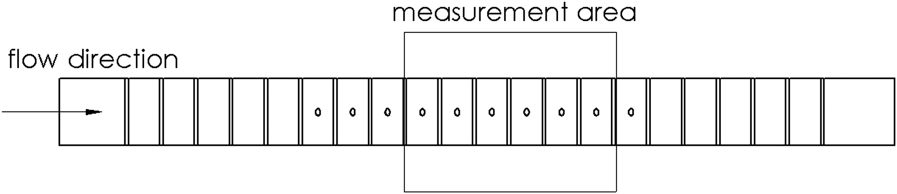
The rectangular cooling channel has an aspect ratio of AR = W/H = 2:1, the rib height-to-hydraulic diameter ratio (e/Dh) is 0.078 and the rib pitch-to-height ratio (P/e) is 10. The cooling channel contains 20 parallel rib segments at the top and bottom wall. Additionally, 10 segments in the centre of the channel are equipped with a film cooling hole at the bottom side only (Figure 2). The cooling holes are oriented at 90° to the incoming cooling flow. The length-to-diameter ratio is L/D = 7, the rib height-to-hole diameter is e/D = 1.5 and the hole diameter D = 5 mm. The inclination of the cooling holes is 35°.
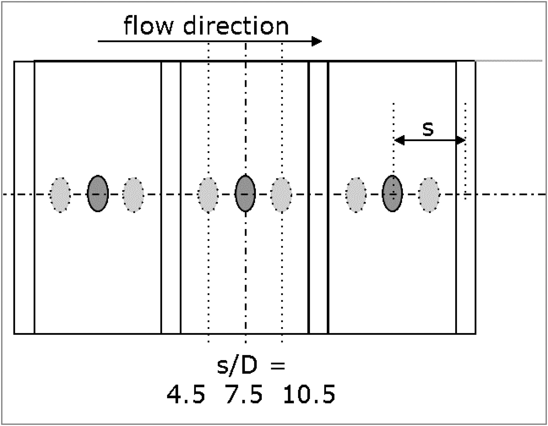
The film cooling hole position is varied as well as the rib geometry. Figure 3 shows the 3 cooling hole positions in a segment, in which the hole is varied in axial position. The applied rib configurations are 90° ribs, 60° ribs, 60°-V-shaped ribs and 60°-Λ-shaped ribs.
Particle-image velocimetry
The flow field in the cooling channel rib segments was measured using the 2D-PIV technique. The light sheets were generated using a frequency-doubled New Wave XT120 laser. The flash-lamp pumped Nd:YAG laser utilised light beams at a wavelength of 532 nm and maximum pulse energy of 120 mJ. The laser light is guided through an articulated mirror arm to the light sheet optics. Two cylindrical lenses were installed in a row to expand a light sheet with a divergence angle of 50° and 1 mm thickness. The light sheet optic was installed on a linear traversing unit to ensure precise positioning of several horizontal measuring planes parallel to the bottom wall, see Figure 1. A CCD-camera (1376 × 1040 pixel), viewing from the top, was used to capture 170 double images of each configuration to ensure the statistical certainty of the average results. The selected frame rate was 6 fps and the pulse spacing 60 µs. The channel Reynolds number was 30.000. The velocity vectors were computed with adaptive cross correlation methods. A seeding generator was used to produce oil particles with a typical particle size of 1 µm. The seeding was applied upstream of the heater, from which the mesh was removed for PIV measurements. Statistical analysis reveals a measurement uncertainty of 2% of absolute velocity at mid span for 95% confidence, while near the side wall the relative uncertainty increases up to 7% due to the lower magnitude of velocity.
Heat transfer measurements
The liquid crystal technique was used to perform transient heat transfer measurements. A step change of the gas temperature is imposed by a mesh heater at the entrance of the Plexiglas channel. The time-dependent surface temperature of the wall is captured by a video camera, monitoring the colour change of the liquid crystals. A RGB-camera with 3 CCD-sensors is used (model: Hitachi HV-F31CL), with an image acquisition rate of 30 fps and a resolution of 1024 × 768 Pixel. The applied liquid crystals of the type Hallcrest R35C1W are used as sheets, which consist of a carrier sheet coated with liquid crystals and black paint.
The heat transfer coefficient is obtained by using the 1D-transient heat conduction equation and treating the wall as semi-infinite solid. The wall temperature response is given by
where Tw,0 is the transient wall temperature of the test surface, T0 the initial surface temperature at thermal equilibrium and TG the gas temperature. The gas temperature is measured with thermocouples, placed in the centre of each rib segment at medium channel height, thus accounting for effects of the upstream rib segments and its extraction. The gas temperature change at channel entrance is close to an ideal step with less than 2 s until the final value is reached and kept constant within
Maximum measuring time was calculated according to Schultz and Jones (1973) and is limited to 230 s with a Plexiglas model thickness of 20 mm. Measurement uncertainty was evaluated with statistical and analytical methods to be 10% of Nusselt number.
Results and discussion
Effect of rib geometry on heat transfer
The rectangular cooling channel of the test rig is equipped with 10 rib segments containing cooling holes. Upstream and downstream of these segments, there are 5 additional segments without holes, providing a developed periodic flow condition (see Figure 2). The following results are depicted for a Reynolds number of 30.000 at channel inlet. The hole extraction is characterized with the suction ratio (SR), as defined in Equation 2. It is calculated as average value from measured volume flow rate over all cooling holes
The pressure ratio at the cooling holes (Figure 4) is determined by measuring the static wall pressure at entrance and outlet of each cooling hole. A constant pressure ratio over the 10 inter-rib segments could be achieved for the three measured suction ratios and all rib geometries. A higher suction shows necessarily a higher pressure gradient over the cooling holes. Zero suction ratio results in a pressure ratio of one. Nevertheless, a minor flow through the holes cannot be eliminated due to a small pressure decline between the first and last holes.

A section of 6 rib segments with cooling holes is observed for the heat transfer measurements in Figure 5. The bottom wall of the cooling channel is shown and the main flow direction is from left to right. The first depicted inter-rib segment in Figure 5 is the 4th segment which contains a cooling hole. The Nusselt number ratio Nu/Nu0 is plotted, where Nu0 is the Dittus-Boelter correlation value for a smooth channel.

The flow in a ribbed cooling channel is characterized by a recirculation region behind each rib, a subsequent reattachment of the flow and a small separation zone upstream of the following rib. Figure 5 shows the heat transfer pattern of a cooling channel with 60° ribs and film cooling holes placed near of the upstream rib (s/D = 4.5). The suction ratio for the cooling holes is SR = 6. Following the inclined obstacle, the flow develops in a transverse direction from the upstream to the downstream rib. The recirculation vortex behind the rib starts from the right sidewall (in flow direction) and expands to the left one. On this account, a region of low heat transfer can be seen directly behind the rib, which expands along the rib in flow direction. Downstream of this region, an area of high heat transfer develops also starting from the corner between upstream rib and right sidewall. A film cooling hole is placed near the edge between high and low heat transfer, respectively between reattachment area and recirculation. Around each cooling hole a heat transfer augmentation takes place. Black lines between the cooling holes and the right sidewall can be noticed, which are the traces of temperature probe cables. A decline of the high heat transfer region in each segment is apparent in the downstream direction and transverse along the rib. A low heat transfer region is then reached at the left sidewall and in front of the following rib. Taking into account the succession of rib segments, a decrease in heat transfer can be seen in downstream direction, which is a result of decreasing mass flow and velocity.
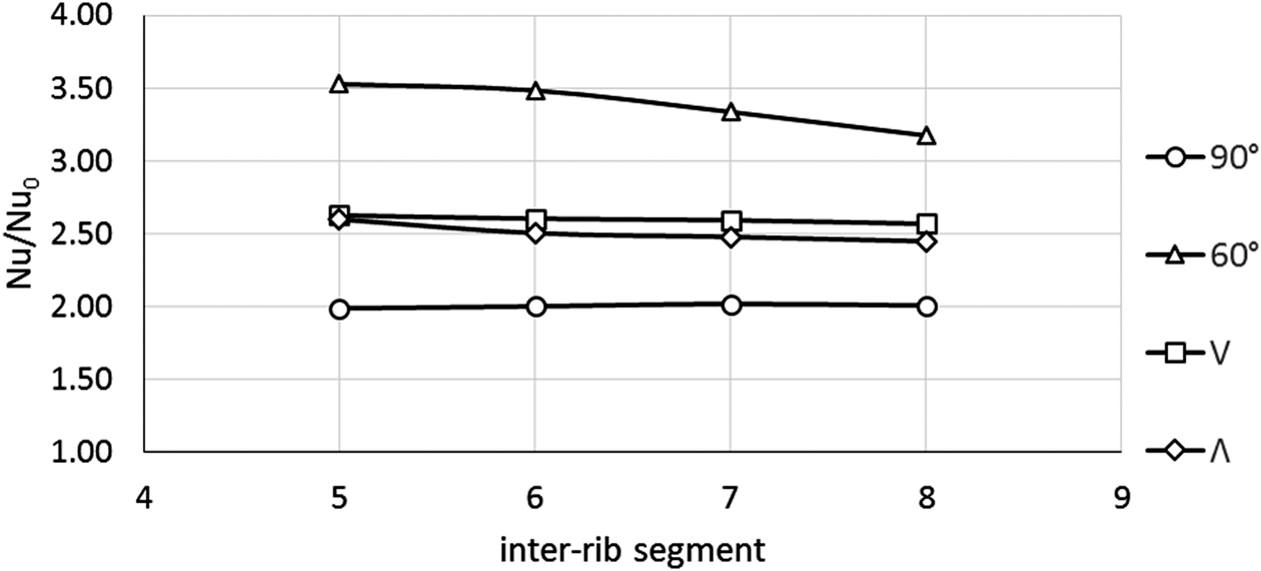
In comparison to the other investigated rib geometries, the 60° rib arrangement has the clearest heat transfer drop as shown in Figure 6. Regional-averaged Nusselt number ratios are displayed for the measured rib segments. Only completely observed inter-rib segments are averaged and plotted. 90° ribs as well as V-ribs show a nearly constant Nusselt number ratio for the 4 rib segments, Λ-ribs a slight decrease. Furthermore the differences in heat transfer augmentation due to the rib geometries can be seen. 60° ribs reach the highest heat transfer augmentation, 90° ribs the lowest with Nu/Nu0 = 2. V- and Λ-ribs are in a similar range (Nu/Nu0 ≈ 2.5–2.6), with Λ-ribs slightly lower.
Comparing the heat transfer levels to literature shows variations in the findings. In contrast to the current study, Han et al. (1991) and Kaewchoothong et al. (2017) found 60°-V-ribs perform slightly better than 60° ribs in a strait channel without coolant extraction. Ekkad et al. (1998) on the other hand reported to reach similar magnitudes in the first pass of a two pass channel with and without coolant extraction. These differences in heat transfer levels can be a result of the various geometric parameters and especially the selection of segments analysed in the experiments. In the current study, a long channel is used, with 5 rib segments to get a developed flow and another 3 segments before the first measured segment. Numerical results, not shown herein, for the actual test case suggest, that V ribs perform superior in the first three rib segments with cooling holes, similar to Han et al. (1991), but show a rapid decline to a lower level in the experimentally investigated segments. Whereas 60° ribs start at lower magnitudes, having a slight increase over the first 3 segments followed by a slower Nusselt number decrease in the successive segments. This clearly supports that variations in the results of different experiments may arise from varying number of segments prior to the measured section.
Effect of cooling flow extraction
The influence of mass flow extraction through film cooling holes is shown in Figures 7 and 8 for a 60° rib case with cooling holes next to the upstream rib (s/D = 4.5). The Nusselt number ratio Nu/Nu0 is depicted for SR = 0 (Figure 7a) and SR = 6 (Figure 7b), as well as the corresponding velocity vectors in Figures 8a and 8b for a horizontal plane at 2/3 of the rib height. The depicted rib-segments are No. 5 and 6 of the segments containing cooling holes.
Figure 8.
Influence of Film Hole Extraction on Flow Field for 60° Ribs, s/D = 4.5, SR = 0 (a) and SR = 6 (b).
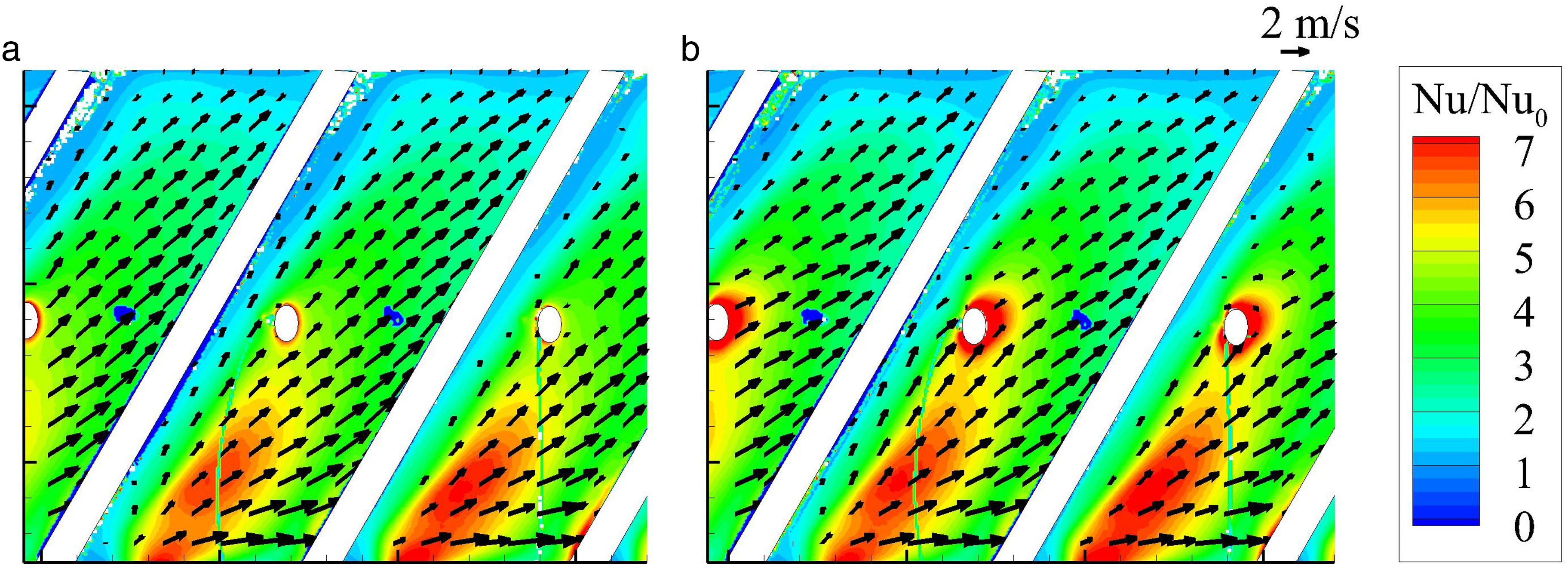
Figure 7.
Influence of Film Hole Extraction on Nusselt Number Ratio for 60° Ribs, s/D = 4.5, SR = 0 (a) and SR = 6 (b).
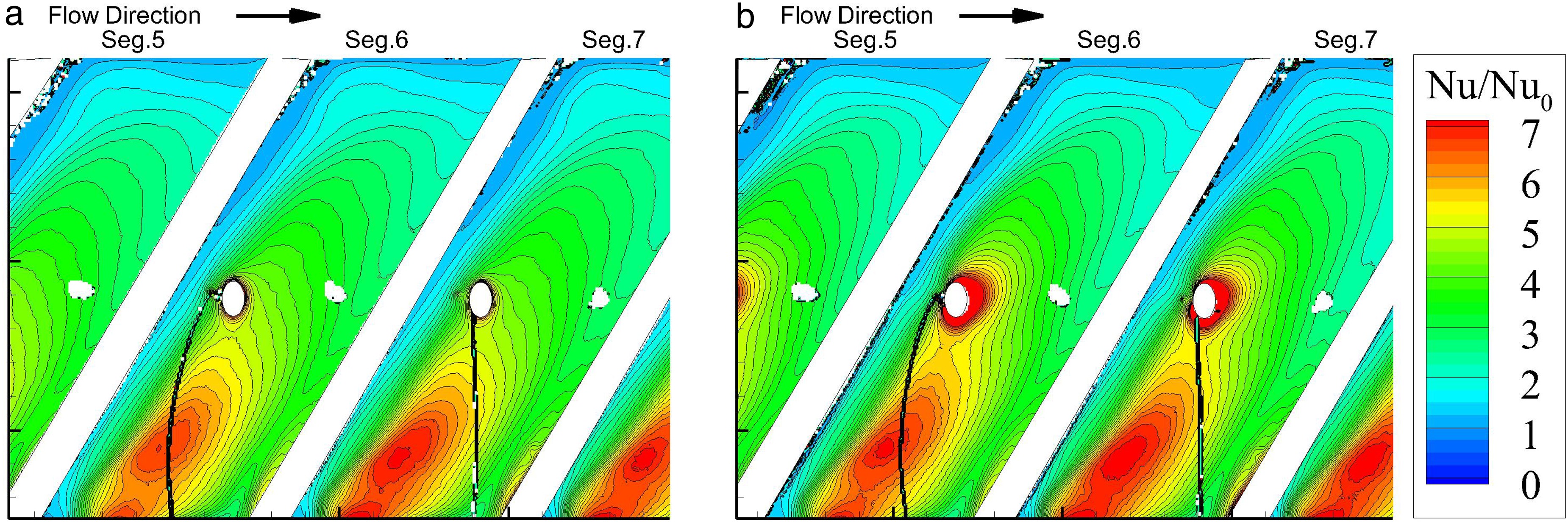
The rib induced flow for the no-bleed case in Figure 7a shows no influence due to the cooling hole. In contrast to that, the cooling hole with bleed (Figure 7b) causes an area of heat transfer augmentation in the vicinity of the hole. The film cooling hole is placed near the recirculation area with low heat transfer. The left edge of the hole, which is located near the recirculation region, shows no heat transfer augmentation. In this area, the flow behind the rib is sucked into the cooling hole. In Figure 8b, the velocity vectors show an inflow into the hole from the axial direction of the nearby rib, as well as from the left-side corner between rib and sidewall. For the no-bleed case (Figure 8a), also the transverse flow behind the rib can be seen, but no axial inflow in the cooling hole. Furthermore the velocity vectors stay unaffected after passing the hole, whereas the velocity vectors are visibly affected for the bleed case (Figure 8b). A reduced velocity can be seen above the hole as a result of the extraction.
As stated in Shen et al. (1996) for 90° ribs, the presence of a bleed hole reduces the extent of slow moving fluid behind the rib. The boundary layer is bled off and the region of high heat transfer immediately behind the hole is build due to the flow attachment in this region. Similar effects can be seen for the depicted 60° ribs. A slight reduction in the recirculation zone along the rib can be noticed, also the high heat transfer behind the hole in downstream flow direction. For 60° ribs the flow develops in transverse direction along the inclined rib. The region of high heat transfer starts from the left corner between rib and sidewall and gradually decreases in the rib-induced flow direction. Due to the heat transfer enhancement of the film cooling hole, the already existing high heat transfer region is widened. Not only the area directly around the hole contributes to the enhancement, also a transition between both regions is formed. However, the low heat transfer region in the right corner of the rib segment, between downstream rib and sidewall, shows a further Nusselt number reduction. The extraction of mass flow through the cooling hole is not exclusively from the separation region, but also from reattachment flow, which lowers the flow magnitude and results in a stronger decrease of heat transfer in downstream direction.
Effect of cooling hole position
Additional to the impact of the presence of cooling holes and the corresponding mass flow extraction, also the positioning of the holes has an effect. Thurman & Poinsatte (2001) and Kunze & Vogeler (2013) investigated the effects of cooling hole positioning within the rib segments for 90° ribs. They showed an enhanced heat transfer for film cooling holes near the upstream rib. The underlying mechanism is, that the hole near the upstream rib sucks the separated flow behind the rib and shortens the recirculation zone. The current heat transfer measurements for 90° ribs, shown in Figure 9, confirm these findings.
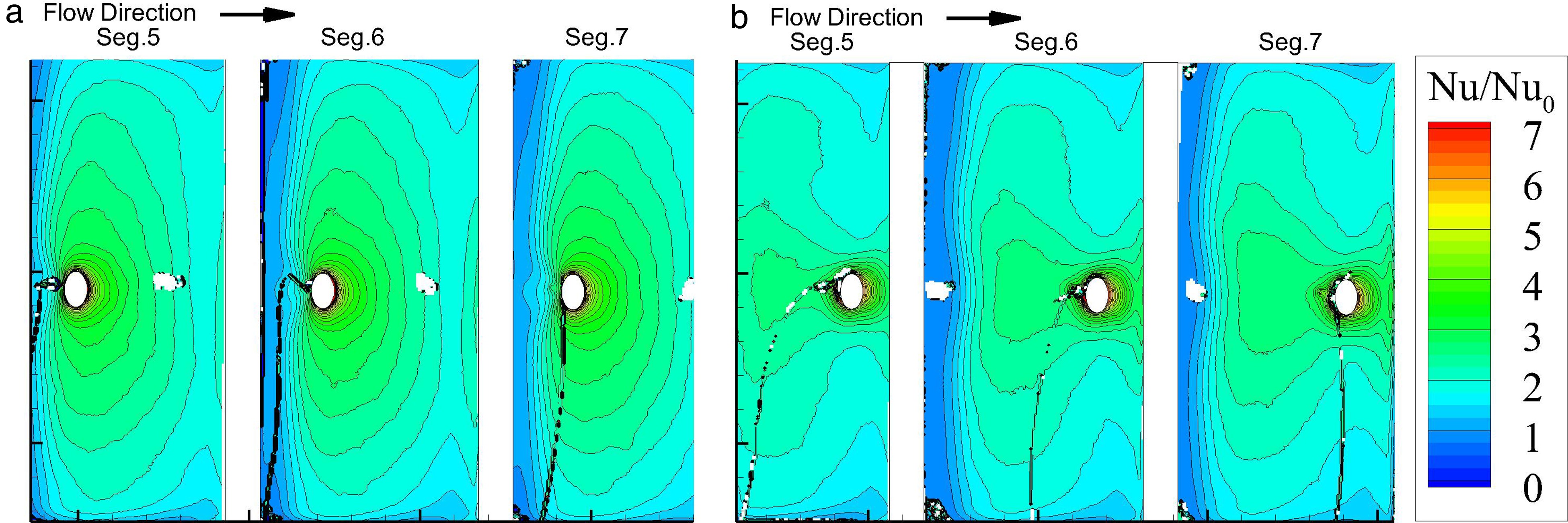
The cooling hole position near the upstream and downstream rib is depicted. The flow direction is from left to right. A recirculation region downstream of each rib is build and a subsequent reattachment of the flow. Immediately before the following rib, the flow separates again to pass the rib. The hole position near the upstream rib (s/D = 4.5) shows an reduced extent of the separation region downstream of the ribs compared to the downstream hole position s/D = 10.5. As the hole near the upstream rib sucks the separated flow behind the rib, the hole position further downstream does not have this effect. The hole position downstream (s/D = 10.5) causes an enhanced heat transfer region just around the hole. The high heat transfer region due to the reattachment is smaller in Figure 9b than in Figure 9a, where the hole is placed directly in this area and enhances heat transfer. Therefore and because of the influenced recirculation region, the average heat transfer for s/D = 4.5 is higher than for s/D = 10.5. For a middle position of the cooling hole between the ribs (s/D = 7.5), the hole would be situated in the region of reattachment with higher heat transfer.
A heat transfer augmentation directly around the hole appears, but less influence on recirculation is achieved and therefore the regional averaged heat transfer is slightly inferior to hole position s/D = 4.5 (see Figure 10).
Figure 10.
Regionally Averaged Nusselt Number Ratio for Varying Cooling Hole Position, SR = 6, Average of Segment 5–8.
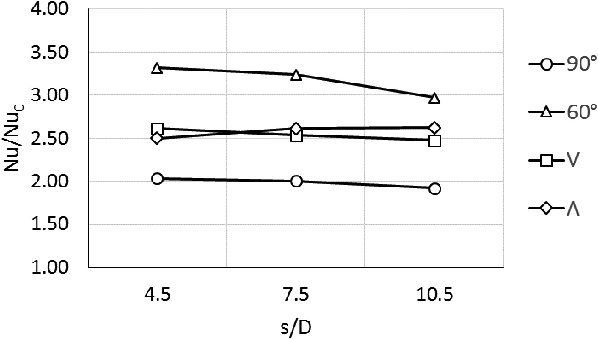
Figure 10 shows the regionally averaged Nusselt number ratio for 90° ribs, 60° ribs, V- ribs and Λ-ribs with varying hole position. Data has been averaged over all fully measured segments, segment 5 to 8 respectively. For 90°-, 60°- and V-ribs, the hole position near the upstream rib (s/D = 4.5) shows the best performance and a decline in heat transfer with further downstream hole positions is achieved. In contrast to that, the Λ-shaped ribs perform better with the downstream positions for the cooling hole, whereas the position just before the following rib is favourable.
To evaluate the underlying mechanism, detailed Nusselt number ratios for the different rib geometries are shown in Figure 11. Complemental near wall velocity vector distributions are illustrated in Figure 12. On the left hand side, hole position s/D = 4.5 is shown and on the right hand side position s/D = 10.5.
Figure 12.
Velocity Vectors at 2/3 Rib Height for 60° Ribs, V-Ribs and inverted V-Ribs, SR = 6, s/D = 4.5 (left) and s/D = 10.5 (right).

Figure 11.
Nusselt Number Ratio for 60° Ribs, V-Ribs and inverted V-Ribs, SR = 6, s/D = 4.5 (left) and s/D = 10.5 (right).

For 60° ribs, the cooling hole position near the upstream rib generates an extended region of high heat transfer from the left-side corner, between rib and sidewall, to the hole. Also the vicinity of the bleed hole shows a heat transfer augmentation. For the hole position further downstream (s/D = 10.5), the high heat transfer area is not widened. The hole is not located in the reattachment area as it is for s/D = 4.5. Instead it is located in the small separation region just before the following rib. Also a heat transfer enhancement in the vicinity of the hole can be noticed, but additionally the areas of low heat transfer are deepened. The velocity vectors in Figures 12a and 12b show an nearly undisturbed flow field around the hole for the downstream position s/D = 10.5. Further downstream along the inclined flow, a stronger descent of velocity and Nusselt number can be seen, than for the upstream hole position. This is because the hole extracts a part of the rib induced main flow, which lacks in the downstream area of the rib segment. In contrast to that, the inflow in the hole for the upstream position s/D = 4.5, is mainly from the recirculation region after the rib, which is sucked from axial and lateral direction. The rib induced main flow is therefore hardly influenced in the downstream area of the rib segment. The underlying mechanism is quite similar to the 90° case, though the flow structures are inclined.
The V-shaped ribs produce a more complex flow pattern. Starting in the middle of the channel, a secondary flow develops which follows the V-shape from the centre to both channel sidewalls (see Figures 12c and 12d). After impinging on the sidewalls, the flow circulates back to the centre of the channel again. Four secondary vortices are created in the cross section of the channel. The heat transfer pattern in Figures 11c and 11d shows the effect of the two vortices along the bottom wall.
A V-shaped region of high heat transfer can be seen, with declining heat transfer from the centre to the sidewalls. The recirculation region also starts from the middle of the channel and develops along the rib towards both sidewalls (see also Figure 12). The recirculation vortex expands outwards and also does the low heat transfer area. Differences in the formation of the heat transfer pattern occur between upstream and downstream cooling hole position. The downstream hole position (s/D = 10.5) shows a more pronounced recirculation region, as it is not extracted by the cooling hole as in the upstream case. Also the starting point of the high heat transfer area has less intensity due to the absence of a cooling hole there. However, the region of high heat transfer is widened in channel main flow direction, due to the cooling hole placed near the following rib. For the hole position next to the upstream rib (s/D = 4.5), a faster decrease of heat transfer in axial direction can be noticed. Nevertheless, the hole position near the upstream rib has the better performance for the regionally averaged heat transfer, as it reduces recirculation after the rib and enhances the high heat transfer starting point, because of the presence of the cooling hole there.
Figures 11e, f and 12e, f show the results for Λ-shaped ribs. The velocity vectors for this rib geometry, as well as for V ribs, can only be illustrated for a part of each rib segment due to shading by the PIV measurements. Nevertheless, the rib induced flow structures can be determined. The secondary flow for Λ-ribs starts from both sidewalls and develops along the rib till both vortices unite in the centre of the channel. Similar to the V-shaped ribs, 4 secondary vortices are build, but the direction of rotation is inverse.
Immediately after the ribs, a low heat transfer area is formed due to the recirculation. Both recirculation vortices also start from the sidewalls, widen along the ribs and unite in the channel centre. Also prior to the following rib, a low heat transfer area is formed. In between, an area with high Nusselt numbers develops. The positioning of the cooling holes indicate the following effects. The hole position near the upstream rib (s/D = 4.5) can slightly reduce the recirculation region, as the comparison to the downstream position s/D = 10.5 shows. Despite of this, the hole position further downstream results in a greater averaged Nusselt number ratio (see Figure 10). The reason can be found by taking into consideration the flow structures. As already seen for the other rib geometries, a bleed hole placed in the area of high heat transfer, provokes a faster decline of heat transfer in downstream direction. Velocity magnitude also diminishes. As the flow structure for Λ-ribs heads to the middle of the following rib, a hole there produces sucking, thereby boosting the velocity and creating an extended attachment area. This effect seems to be superior to the extraction of the recirculation area downstream of the prior rib. Moreover, the hole also sucks the separated flow in front of the following rib.
Conclusions
Heat transfer and flow measurements were obtained in a stationary blade coolant channel. Different turbulence promoters were used: 90° ribs, 60° ribs, 60°-V ribs and 60°-Λ ribs. The influence of streamwise positioning of film cooling holes within the rib segments was investigated.
The application of ribs as turbulence promoters in cooling channels causes a strong secondary flow structure, due to the interaction between rib-induced flow and main flow. From previous research it is known, that 90° ribs show a recirculation region downstream of each rib, a reattachment area and a second separation region prior to the following rib. Also 60° ribs show these structures, but with an inclined flow direction and thereby additionally generating two vortices in the channel cross section. For high performance ribs, the secondary vortices are more complex. V and Λ ribs develop a secondary flow structure with two counter-rotating vortices at the channel top and bottom side. As the rib direction is inverted, also the direction of rotation of the vortices is inverted. Therefore, the V ribs form a flow structure, starting in the channel centre and the Λ ribs generate vortices, starting from the sidewalls and uniting in the centre of the channel.
The current study showed, that a cooling hole near the upstream rib causes an extraction of the low momentum flow behind the rib and reduces the size of the recirculation region. As this was already known from previous studies for 90° ribs, the current investigation showed, that this also applies for 60°, V and Λ ribs.
Since the flow structures have a major effect, hole positioning in other regions of the rib segment can also be reasonable.
Although Λ ribs show a decreased recirculation size, with a cooling hole near the upstream rib, the regionally averaged heat transfer is better, when the cooling hole is positioned further downstream. The reason is the vortice structure, which starts from the sidewalls and goes to the channel centre. A placement of holes along the channel centre can enhance the flow structure, when sucking flow. Certainly, to enhance the flow of the reattachment structure and therefore the internal heat transfer, the hole position should be downstream of the uniting point of the vortices. Of course, internal heat transfer must be traded with external film cooling effectiveness in the designing process.
The authors assume, that also for other complex rib configurations, a second region in the rib segment, additional to the upstream position of the cooling hole, can exist, which is superior in its heat transfer augmentation.
Nomenclature
α
thermal diffusivity of Plexiglas [m2/s]
h
heat transfer coefficient [W/m2/K]
AR
channel aspect ratio (=W/H) [−]
D
hole diameter [m]
Dh
hydraulic diameter [m]
e
rib height [m]
H
channel height [m]
L
hole length [m]
λ
thermal conductivity of Plexiglas [W/m/K]
mass flow rate [kg/s]
Nu
Nusselt number [−]
Nu0
Nusselt number for a smooth channel (from Dittus-Boelter corr.) [−]
P
rib pitch [m]
static pressure [Pa]
total pressure [Pa]
Pr
Prandtl number [−]
Re
Reynolds number [−]
density [kg/m3]
s
rib distance from hole [m]
SR
suction ratio (=uh/uc) [−]
t
time of liquid crystal colour change [s]
TG
gas temperature [K]
T0
initial surface temperature [K]
TW,0
transient wall temperature [K]
uc
cooling channel velocity [m/s]
uh
cooling hole velocity [m/s]
flow rate of extracted cooling air [m3/s]
W
channel width [m]