
Introduction
Over 10% of the global final energy demand is attributed to high-temperature (T > 400°C) industrial fossil-fuel-based heat requirements alone (IRENA, 2016; de Pee et al., 2018). In contrast with low-temperature heat, which can be decarbonised with more mature technologies such as heat pumps, economically and technically feasible technologies aimed at decarbonising high-temperature industrial heat are limited. One vital industry requiring urgent innovation is the highly energy-intensive steam cracking industry, where ∼110 million tonnes of natural gas (equivalent to ∼4% of global natural gas consumption from all sectors) are consumed annually (Mynko et al., 2022). As a result, a staggering ∼300 million tonnes of CO2 are emitted per year (Keller et al., 2020), accounting for 30% of global emissions from the chemical and petrochemical industries.
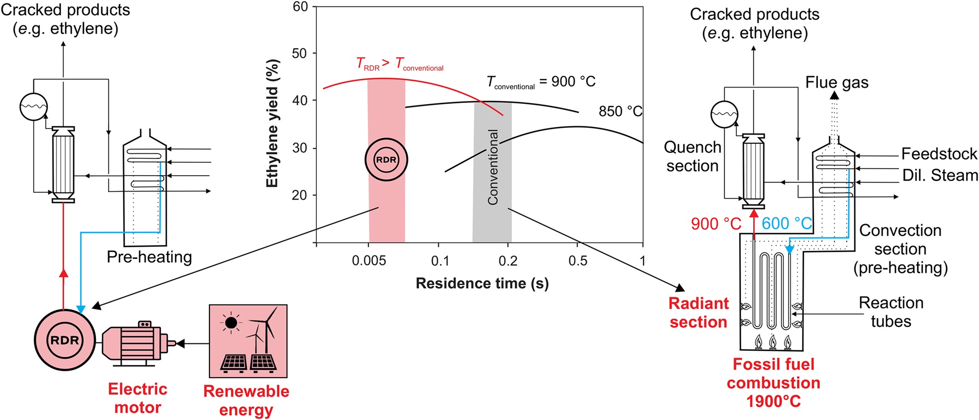
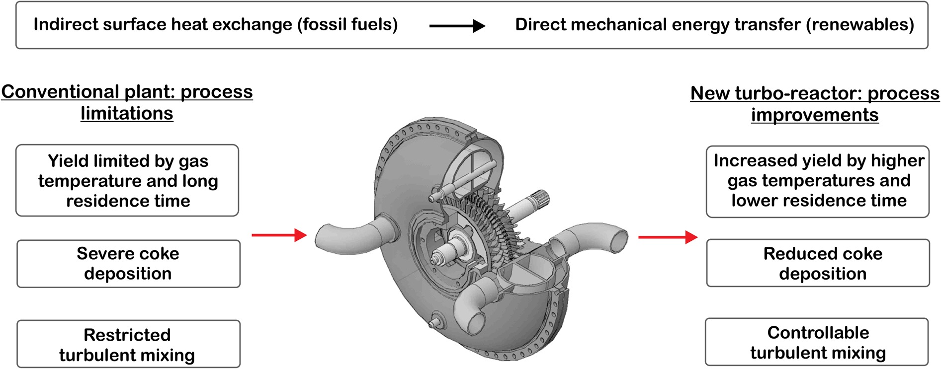
This paper presents a new turbo-reactor as an economically and technically feasible solution which could potentially decarbonise the hydrocarbon cracking industry. Figure 1 shows the novel concept which eliminates the fundamental limitations of the conventional process by replacing the inefficient, ineffective and indirect surface heat exchange energy transfer mechanism in the radiant section with efficient and direct mechanical energy transfer using an electric-motor-driven turbomachine.
Figure 1.
A schematic of an ethylene production plant including the turbo-reactor (left) and a conventional steam cracking furnace (right). The middle schematic shows how shorter residence times higher temperatures can increase the yield (adapted from Chauvel and Lefebvre (1989)).
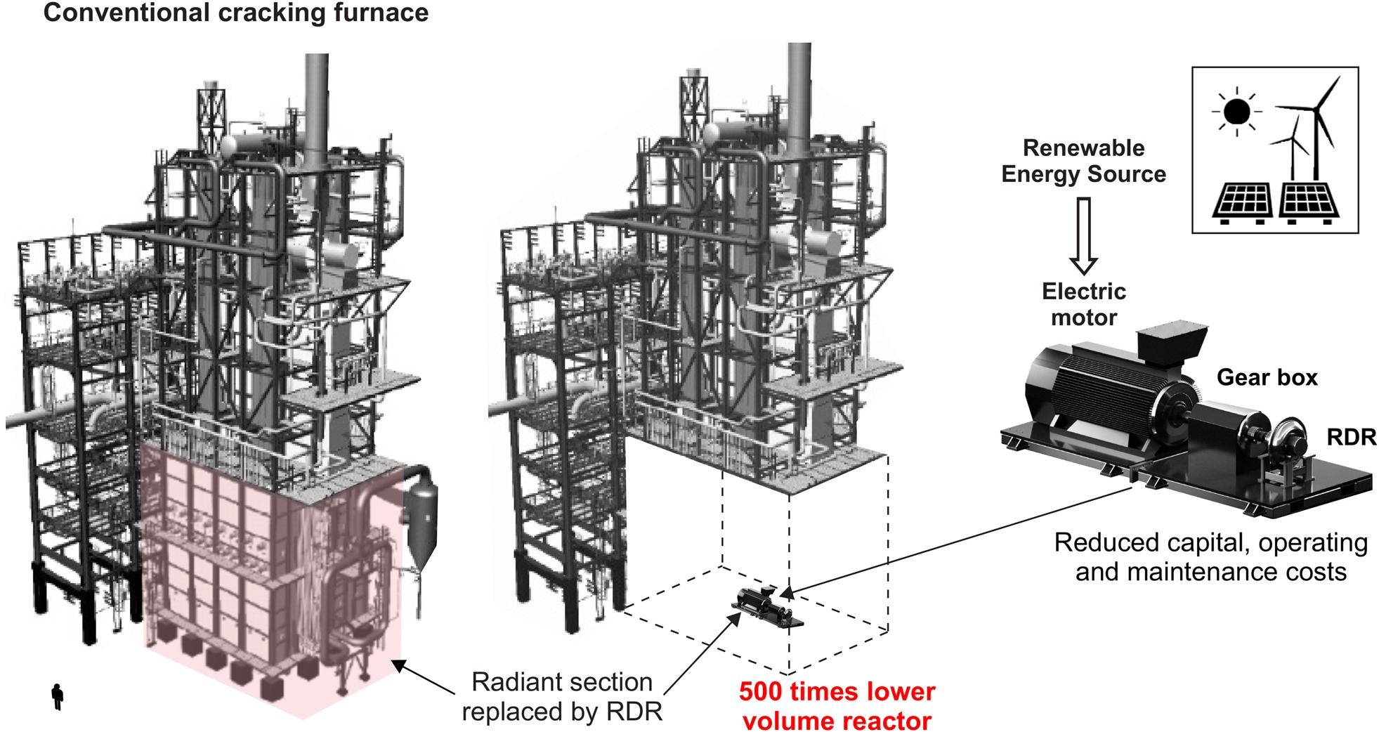
Based on the levelised cost of electricity, grid-parity is being achieved for utility-scale solar PV as well as onshore wind (IRENA, 2014). Coupled with wide-spread carbon tax deployment in the near future, this could mean that powering the cracking process using cheap renewable electricity will become a significantly more attractive solution than natural gas combustion within a furnace. Complete renewable electrification of this unit would decrease CO2 emissions by at least 70% for a steam cracking plant. Most importantly, Figure 2 demonstrates that the new turbo-reactor provides the necessary enthalpy rise for the endothermic cracking reactions within a low-cost, single-rotor, and compact machine with a volume approximately 500 times smaller than a conventional furnace. This on its own is a potential step-change improvement for the cracking industry.
Figure 2.
A size comparison between the radiant section (adapted from Linde Engineering (2020)) and a scaled representation of the RDR within a steam cracking plant.
The new turbo-reactor, the Roto-Dynamic Reactor (RDR), not only enables a more efficient low-carbon energy transfer and transformation process, but also has the potential to substantially improve the quality and controllability of the overall cracking process. This includes a projected increase in the desired primary product yield (see Figure 1) as well as a substantial reduction in coke formation and deposition rates. One important mechanism to accomplish this is a controlled residence time reduction (see Figure 1 (middle)), which is achieved using energy transfer and transformation processes of a shorter time-scale and higher reaction temperature. This is enabled by exploiting an ultra-high loading rotor and a shockwave system.
Alternative zero-carbon technologies which could replace the conventional furnace include zero-carbon fuel-switching (e.g., hydrogen (Haydock and Napp, 2013)) or the use of electric furnaces (Amghizar et al., 2020). However, these technologies do not overcome the fundamental limitations of the (exergetically) inefficient and ineffective surface heat exchange energy transfer mechanism, nor do they enhance the quality of the process.
This numerical study illustrates how the working principals of the single elemental stage (Rubini et al., 2021) can be realised in the context of a regenerative multi-stage environment. The robust concept ensures the required conditions for high-quality cracking are maintained for all stages of the turbo-reactor, whilst using a simple, uniform, compact, and low-cost design. In contrast with conventional reaction tubes, the turbomachine is highly controllable, allowing the level of specific energy imparted, temperature profile, pressure profile and mixing intensity to be tuned to provide the necessary cracking severity during operation.
Conventional hydrocarbon cracking process
The heart of the cracking process is the radiant section (see Figure 1 (right)) which provides the large enthalpy of reaction to thermally decompose (crack) a wide variety of long-chain hydrocarbon feedstocks (e.g., naphtha or bio-feeds) into a broad range of short-chain high-value light olefins (e.g., ethylene). These final products are essential building blocks for a wide range of industrial and domestic products. The radiant furnace is the most important unit of the plant and is the section that the new electric-motor-driven turbo-reactor has been developed to replace (as shown in Figure 1 (left)).
Before the feedstock enters the radiant section, it is mixed with steam in order to reduce the olefin partial pressure and therefore minimise the level of yield-degrading secondary reactions. Following the blue line through the convention section shown in Figure 1 (right), the gas mixture is preheated by heat exchange with the flue gas (the dotted black line originating from the radiant section). In the radiant section, the radiative heat flux from the combustion of fossil fuels (e.g., natural gas) drive the endothermic cracking reactions as well as raising the temperature of the gas mixture from ∼600°C to ∼900°C along the reaction tubes. Downstream of the radiant section, the gas mixture is rapidly cooled in the quenching unit in order to freeze the gas composition. The cracked product mixture (primary ethylene and propylene alongside secondary products) is compressed, chemically treated, and separated into the desired final products.
Addressing the fundamental limitations of the process using a new turbo-reactor
The primary product yield and the level of coke deposition are two key metrics defining the quality of the process. High fluid temperatures (see Figure 1), low metal temperatures, short residence times, as well as a constant olefin partial pressure are the key drivers which can increase the yield and curtail coke deposition. These parameters have limited scope for improvement in conventional designs. The proceeding section highlights how the new turbo-reactor removes the fundamental limitations of the conventional furnace to provide an efficient energy transfer mechanism whilst at the same time substantially improving the effectiveness and quality of the cracking process.
The Roto-Dynamic Reactor (RDR) concept and detailed design have been developed over many years of collaboration with Coolbrook Oy (2020) and are based on the original patent by Bushuev (2016).
Efficient energy transfer as work input for the chemical reactions
Conventional process limitation. The prevailing radiative heat transfer mechanism in the radiant section (where high heat fluxes are required) necessitates very large temperature differences to drive energy transfer. Therefore, the exergy destruction here dominates and contributes to a deleteriously low rational exergy efficiency of 43% for the furnace (Yuan et al., 2019).
Turbo-reactor solution. Mechanical energy (i.e., pure exergy) is imparted directly by the aerodynamic action of a rotating blade row. This eliminates the demand for large temperature differences within the system to drive the heat fluxes in the energy transfer process. As a result, the energy is directly imparted into the reactants without significant heat loss, especially with the application of effective modern thermal protection to minimise irreversible heat losses. It will be demonstrated that the required enthalpy can be provided using only a single-rotor blade row within a ∼500 times smaller volume reactor than a conventional furnace. It is also noted that the operating temperature (Tmax ≈ 900 – 1050 °C) and pressure (p ≈ 1.5 – 3.0 bar) are less severe than those experienced in conventional gas turbines; therefore, available and mature material technology can be used.
Increasing the yield though high gas temperatures and short residence times
Conventional process limitation. Indirect surface heat exchange in the radiant section requires the walls to be at a significantly higher temperature than the gas mixture within the reaction tubes, often by 150°C (Van Goethem, 2010). Therefore, the working fluid temperature is fixed by the metallurgical constraints of the tubes as well as by the acute coke deposition rates associated with the elevated metal temperature. Figure 1 illustrates that this fixes the optimum residence time required to maximise the yield at a given temperature level.
Even supposing higher gas temperatures were possible, the limitations of the conventional design make it challenging to reduce the residence time to the optimum value required to maximise the yield at the higher temperature profile (see Figure 1). This is because the fluid velocity is fixed by the pipe geometry and pressure losses, and the gas path length is fixed by the necessary heat transfer surface area.
Turbo-reactor solution. In contrast with a conventional furnace, the average metal temperature is lower than that of the working fluid. Therefore, higher gas temperatures can be attained without the walls reaching the critical yielding value, whilst at the same time alleviating coke deposition. In conjunction with this, lower residence times are now feasible, firstly, because the requirement for a large heat transfer surface area is removed (thus allowing a shorter gas path), and secondly because the fluid can reach significantly higher throughflow speeds than within a pipe. Figure 1 indicates that these factors lead to the necessary conditions to increase the yield by reducing the residence time to match the increased temperature.
Potential to reduce coke formation and deposition
Conventional process limitation. Coke formation and deposition is the primary challenge impacting plant availability, operating and maintenance costs, and component lifetime. Generally, coke deposition is magnified by high wall temperatures and low surface viscous shear stresses, as well as long residence times and elevated olefin partial pressure.
Coke is continually deposited on the inner wall surface and accumulates over time. This leads to an effective thermal resistance up to 80% higher than for a bare tube (Zhang et al., 2022). To maintain the same cracking severity and product yield, the resulting increase in thermal resistance is compensated for by increasing the fuel flow rate to the burners, therefore raising the tube metal temperature and further exacerbating coking. As a result, coke deposition provides a stringent restriction on the allowable gas temperatures within the tubes which thus limits the yield. Coupled with this, coking reduces olefin selectivity by increasing the pressure drop, as well as reducing component lifetime by increasing thermal stresses. After several weeks, coke can occupy up to ∼50% of the cross-sectional area of the reaction tube (Vandewalle et al., 2017). Therefore once a critical tube metal temperature or pressure drop is reached, the furnace is taken completely offline for a 48 h decoking period which occurs as frequently as every 6 weeks (Schietekat et al., 2014) and adversely affects the profitability of the plant.
Turbo-reactor solution. The new turbo-reactor provides the necessary conditions to potentially reduce coke formation and deposition. This is achieved through a significantly lower wall metal temperature and by eliminating the outward wall temperature gradient (from metal to fluid), in addition to shorter residence times.
Controllability
Conventional process limitation. Due to the nature of the fixed pipe geometry in conventional reaction tubes, the only available control parameters are the initial temperature and pressure of the feedstock and the amount of the fuel supplied to the burners. Accurate control over the temperature, pressure, and residence time distributions along the tubes is challenging.
Turbo-reactor solution. Through careful aerothermal design and operational control (e.g., varying the rotational speed and mass flow rate), turbomachines have a high level of control over the temperature and pressure distributions, specific enthalpy increase, as well as the chemical reaction rate, residence time, turbulent mixing of species, and the steam feed injection staging. This enables controllable tailoring of the olefin selectivity and product yield.
The turbo-reactor concept
Three-blade-row elemental stage and regenerative heating concept
Based on the design requirements necessary to provide the optimum conditions for cracking, the repeating elemental stage consists of a novel three-blade-row design including stator, rotor and diffuser blade rows (see Figure 3a).
Figure 3.
(a) A linearised schematic showing the hemi-annulus and the blade velocity triangles (b) The Hemi-annulus schematic (c) The full reactor model.
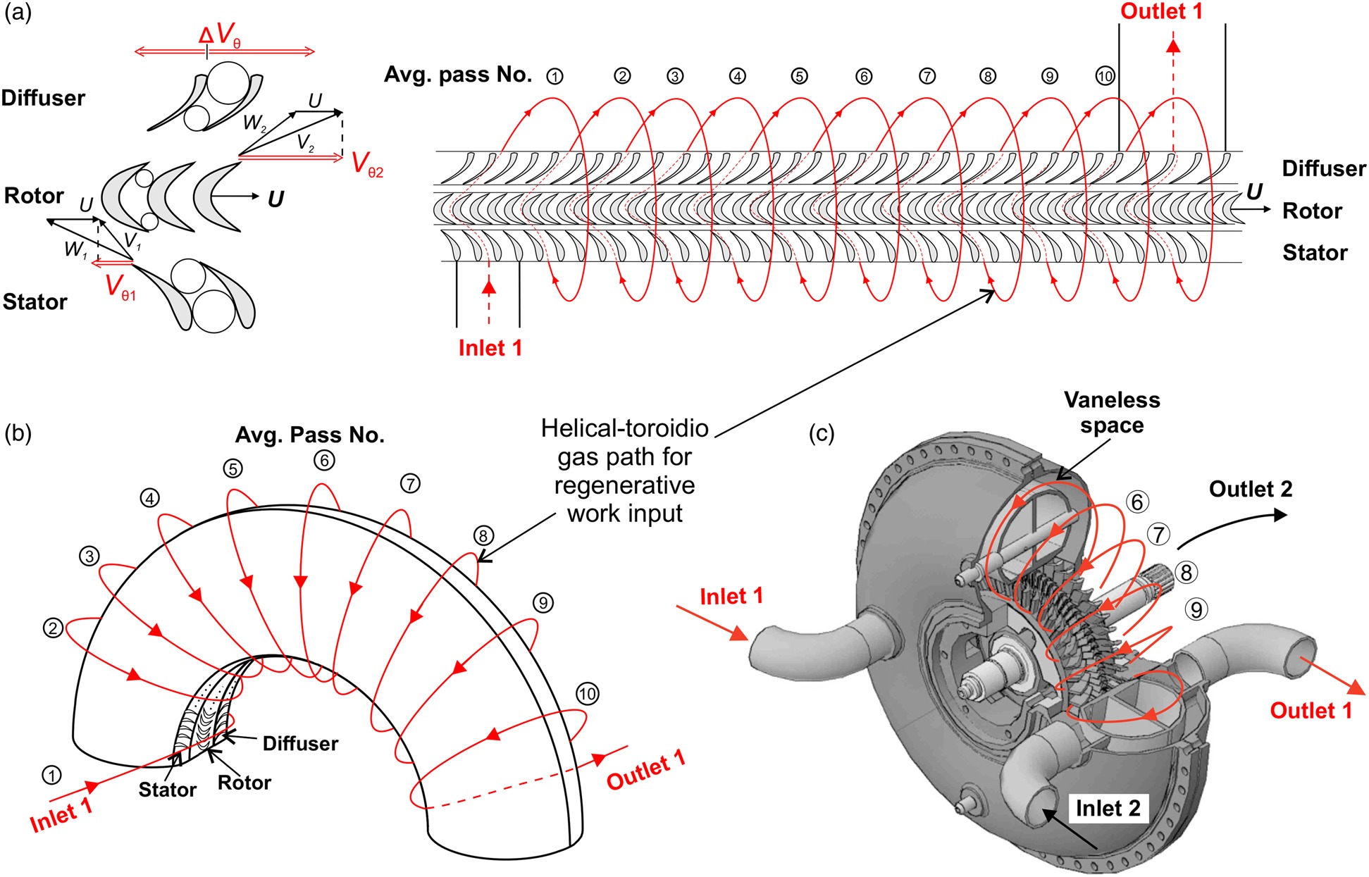
The stator blades (inlet guide vanes) are designed to accelerate, pre-condition and pre-swirl the flow. The proceeding sections highlight how a controllable optimisation of the residence time (and hence yield) is enabled using a transonic ultra-high loading rotor and a complex shock system in the diffuser blade row. This facilitates ultra-short-distance energy transfer and transformation processes. The transonic diffuser is multi-functional, but its primary function is to turn and slow down the high-speed flow, as well as transform kinetic into internal energy for the reaction whilst also maintaining a constant static pressure level (optimum for cracking) downstream.
The work input across a single elemental stage does not provide a sufficient total enthalpy rise to complete the cracking reactions, therefore, a multi-stage configuration is necessary. In this version of the turbo-reactor, this is achieved regeneratively using only a single rotor blade-row. Figure 3 shows that a series of regenerative passes (indicated in red) are used to compound the total enthalpy rise across the machine for the chemical reaction. Following the red line, a single regenerative pass constitutes an average particle traversing the stator, rotor and diffuser blade-rows, before following a helical-toroidio gas path in the vaneless mixing/reacting space. The gas path indicated in red in Figure 3 illustrates that the diffuser trailing edge (TE) allows sufficient residual swirl to progress the flow through the vaneless space to re-enter the next stator passages shifted in the circumferential direction. The regenerative multi-pass design has a similar effect to multiple turbomachinery stages in series. The vaneless space is formed between the inner and outer casing, as shown in Figure 3c. It is noted that the helical-toroidio regenerative flow path is similar to that in a regenerative compressor (Sixsmith and Altmann, 1977).
The regenerative process is repeated for up to 10 designed passes of repeated turns before exiting through the outlet pipe. Figure 3c shows a second independent but identical hemi-annulus which is mirrored in the lower half of the full reactor, resulting in two inlet and two outlet ports.
The unique advantage of the regenerative turbomachine is that it uses only a single rotor with a short shaft length, resulting in a compact low-cost reactor ideal for small-scale production. Various complementary architectures are being investigated for large-scale production capacity. Nonetheless, for increased capacity a multiplicity of these compact regenerative machines can be run in parallel.
Numerical methodology
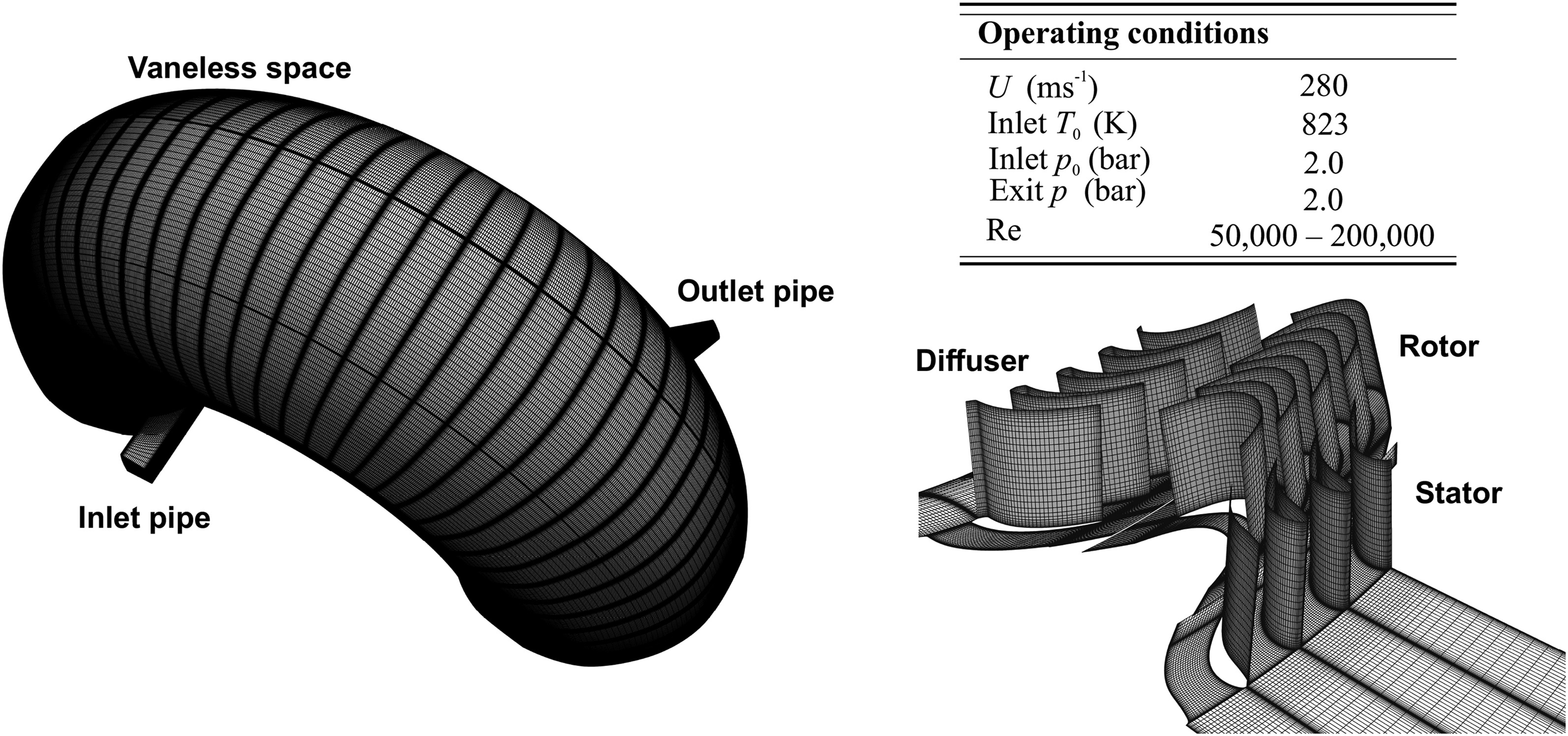
The feasibility of the concept has been proved with a numerical model simulated within the in-house computational fluid dynamics code TBLOCK developed by John Denton (Denton, 1982, 1986, 1992). The solver has been applied to a wide range of flow physics within as broad range of turbines and compressors test cases, as well as being extensively validated against experimental data. The experimental validation of the solver most relevant to the study presented here is the work of Rosic et al. (2005). This work confirmed the capabilities of TBLOCK against experiment data for a multi-stage turbine with a Reynolds number similar to that in the new turbo-reactor (see the table in Figure 4). In addition to URANS calculations, high-fidelity large eddy simulations (LES) have been employed to more accurately capture the mixing-out of large-scale coherent turbulent flow structures and improve the resolution of shockwave boundary layer interaction.
Different subgrid scale (SGS) models have been implemented in the solver by Klostermier (Klostermeier, 2008). The SGS model used for the present computation is the Smagorinsky model coupled with the Van Driest damping function. The present work adopts an adiabatic wall as the thermal boundary condition for the energy equation. Additionally, a semi-perfect gas consisting of a single species with constant chemical composition is assumed. The gas composition is very close to the average of the inlet gas mixture (naphtha and steam) and the cracked product mixture at the outlet. In the CFD model presented, there is no chemical reaction model yet as the primary focus of this preliminary design is on the aero-thermodynamics of the turbo-reactor.
Computational domain
The URANS domain shown in Figure 4 consists of 527 blocks with 48 × 32 × 32 nodes in the axial, pitchwise and spanwise directions within blade passages (totalling to 16 × 106 grid points). Turbulence is modelled using wall functions and an algebraic mixing length model.
The justification for the mesh density which has been used for the URANS calculations is two-fold. Firstly, the required mesh density is a function of the turbulence closure model, which in this case is a mixing length model. Therefore, the sensitivity to mesh density is minimised. Secondly, the mesh density is dictated by the physical phenomena of interest. In this study, only zeroth-order parameters of the elemental stage are of primary concern. Namely, the present work aims to confirm that the stage achieves the required work input (enthalpy gain) at the flow coefficient that is necessary to maintain the required throughflow capacity. These bulk flow parameters are relativity insensitive to the mesh density. Since flow coefficient and work coefficient are the primary parameters of interest, they are used to define the objective function used for a mesh sensitivity analysis. For investigations into detailed flow physics and flow structures, the mesh-dependency is greater. However in such cases, LES is used in this study.
For consistency, during the mesh sensitivity study the wall expansion ratio is kept constant and the number of grid points in each direction of the computational space are scaled equally. Table 1 illustrates that the maximum variation in stage loading and flow coefficient is about 0.5% across the different mesh resolutions. Relatively low deviations are expected since the flow in the blade passages is predominantly pressure driven. Similar deviations are observed for other flow parameters of interest, such as pressure, internal energy and dissipation rate along the gas path.
Table 1.
Mesh sensitivity study.
| Coarse | Medium | Fine | |
|---|---|---|---|
| No. grid nodes (bladed path) | 48 × 32 × 32 | 81 × 51 × 51 | 91 × 71 × 71 |
| Stage loading | 4.05 | 4.10 | 4.07 |
| Flow coefficient | 0.6009 | 0.6054 | 0.6033 |
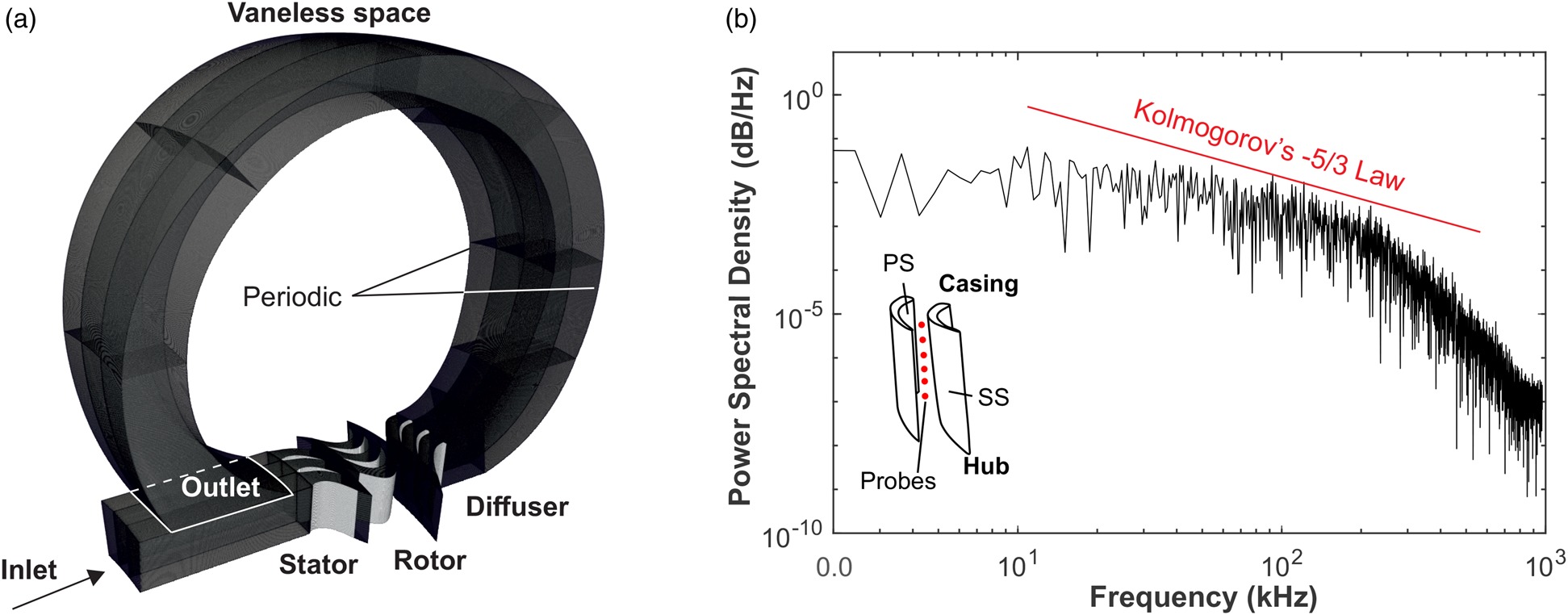
The regenerative nature of the process allows for a truncated domain (consisting of a single pass or streamtube to be modelled when conducting the LES (see Figure 5a). The exit static pressure boundary condition (p = 2.1 bar) is placed at the end of the vaneless space based on a precursor URANS simulation of the full hemi-annulus. A periodic boundary condition is applied to the lateral surfaces of the domain. The LES domain consists of 48 blocks with 241 × 131 × 131 nodes in the axial, pitchwise and spanwise directions within the blade passages (totalling 150 × 106 grid nodes across the domain), resulting in a time-averaged y+ between 0.1 – 1.0. The energy cascade shown in Figure 5b suggests that the LES is capable of resolving the time scales of the energy carrying eddies in the inertial sub-range of the Kolmogorov energy spectrum, strengthening the validity of the numerical results.
Results and discussion
Short-distance work input: ultra-high loading rotor
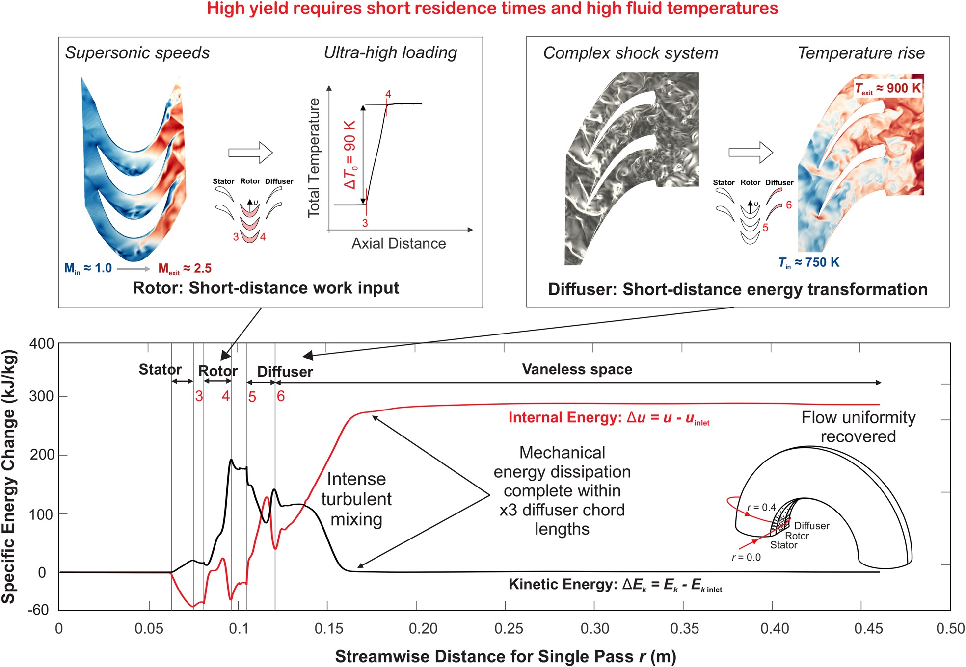
The novel design requirements of the new turbo-reactor require high work input and energy transformation rates in order to controllably optimise the residence time and thus maximise the yield. These conditions are provided by the energy transformation train illustrated in Figure 6. One key component of the energy train is the ultra-high loading transonic rotor, which is used to impart the required energy into the working fluid over an extremely short distance and time scale. For a given mass flow, the primary objective of the turbo-reactor is to maximise the amount of energy imparted, which can then be dissipated into internal energy to drive the reaction. Therefore, stage loading is used as a metric to quantify aerothermal performance.
Figure 6.
Energy transformation train along a single gas path: time- and mass-averaged specific internal u and specific kinetic energy Ek changes referenced as a change relative to the inlet values (LES).
Based on the specific design objectives and operating conditions, a rotor stage-loading coefficient
Short-distance energy transformation: diffuser shock system
In contrast with the more conventional stator and rotor blade rows, the diffuser is multi-functional with three primary objectives which are highlighted in Figure 6.
Firstly, the diffuser transforms the bulk kinetic energy of the flow provided by the rotor into internal energy for the reaction. This is achieved using a shock train system to slow the high-speed flow down within the passage. Secondly, the diffuser is designed to promote large-scale flow separation and mixing in passage in order to prevent pressure accumulation whilst dissipating the kinetic energy, primarily through intense shockwave boundary layer interaction (SWBLI) and shock-induced flow separation (see Figure 6). This is necessary in order to maintain a constant static pressure level which maximises the olefin production rate (by reducing side reactions) and promoting homogeneity in the temperature and species field. Finally, as a consequence of highly impulsive rotor blading, the diffuser must turn the flow through a large angle (almost back into the axial direction) in order to allow the flow to progress regeneratively downstream of the diffuser TE. The high-turning blade profile further promotes shockwaves in the passage as well as augmenting the mixing levels through increased flow separation.
Figure 6 (bottom) shows that the energy transformation processes are complete within approximately three diffuser chord lengths downstream into the vaneless space, before the flow conditioning process commences in order to recover flow uniformity.
Controlled turbulent mixing and flow conditioning processes
The vaneless mixing/reacting space shown in Figure 7a has two primary functions and can be split into two distinct zones: the primary mixing/reaction zone and the flow conditioning zone. As a result of a thick diffuser TE, high-energy turbulent mixing, driven by large coherent vortical structures (e.g., vortex shedding), propagates into the vaneless space. The controlled mixing process generates the ideal conditions for cracking by maintaining a constant static pressure level, homogenising the temperature field, converting kinetic into internal energy, and possibly accelerating the chemical kinetics.
Figure 7.
(a) Instantaneous (LES) Q-criterion iso-surfaces (b) Time-averaged (LES) wall shear stress contour on the vaneless space outer casing.

Within three diffuser chord lengths, due to the low Reynolds number regime (50,000–200,000) throughout the vaneless space, flow uniformity is rapidly recovered (see Figure 7) and the pressure is relieved back to the inlet level. Detailed studies (Rubini et al., 2021) have shown that the turbulence intensity decays rapidly downstream of the high-energy mixing zone. In addition, the momentum thickness Reynolds number and shape factor, two parameters which characterise the state of the boundary layer, both recover back to similar values to those of the clean flow within the inlet pipe.
Figure 7b shows the time-averaged footprint of large length-scale vortical structures which are stretched as the flow regains uniformity. Any vortical structures or turbulent fluctuations that persist before the next pass will be stretched and dissipated by rapid acceleration in the stator. It can also be seen that in the majority of the vaneless space, the level of lateral mixing between passes is low, which is important for the quality and effectiveness of the regenerative design. Before the next rotor stage, the flow is in a well conditioned state which maximises the work input potential of the following stage. Figures 6 and 7 both indicate that the mixing and energy conversion processes are complete before 50% of the length of the vaneless space, suggesting that tuning the vaneless space length (and hence residence time and reactor volume) is possible without influencing the flow conditioning for the next pass. This is further supported from a residence time control perspective since 80% of the total residence time is spent in the vaneless space.
Multi-pass regenerative energy input concept
Each successive regenerative pass repeats the processes described above for the elemental stage, resulting in a multi-pass regenerative heating concept as shown in Figure 8a. The following sections illustrate how the working principals of the elemental stage, described above, can be realised uniformly and effectively for all regenerative passes.
Figure 8.
Time-averaged (URANS): (a) streamtraces (b) enthalpy change referenced relative to the inlet conditions.
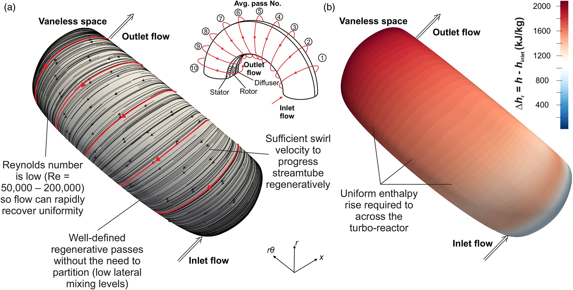
Figure 8a illustrates that there is sufficient tangential velocity at the diffuser TE to progress the flow regeneratively to the subsequent stator passages. For all regenerative passes, the streamtraces indicate that the flow is well-conditioned and that uniformity has been recovered downstream of the mixing zone. The open-volume vaneless space is robust enough to allow the streamlines to self-correct and form clearly defined passes without the need to partition the flow (see Figure 8).
Ideally, the streamtubes defining the passes must be independent in order to prevent lateral mass transfer of species between passes (which would degrade the performance of the reaction), preserve the required peak temperature for cracking, and maintain the design velocity triangles. The pattern of the streamtraces in Figure 8 indicate that the level of lateral mixing between adjacent regenerative passes is low. If necessary, this can be further controlled by partitioning each pass with thin guidewalls the vaneless space.
Figure 8b shows a uniform static enthalpy rise (relative to the inlet conditions) circumferentially across the reactor. For chemically reacting flow, depending on the dynamics of the reaction, the static enthalpy profile will be different to that shown in Figure 8b. Nevertheless, it has been clearly demonstrated that the necessary enthalpy rise for consumption by the endothermic cracking reactions can be provided within a compact, single-rotor turbomachine. This is achieved whilst maintaining a low wall temperature and mitigating coke deposition. The residence time for an average particle undergoing regenerative work input is 5–10 times lower than that for a conventional furnace. Coupled with the increased process gas temperatures, this could potentially increase the combined ethylene and propylene yield by 20% (Coolbrook Oy, private communication, 2019).
Robust aerothermal concept
The robustness of the aerothermal concept is enabled through the unique regenerative open-volume design. This robustness is characterised by two intrinsic features of the concept: a guaranteed pressure equilibrium, and the tolerance to density variations in spite of a low-cost, uniform casing and blade design.
Figure 9a illustrates that a constant static pressure level (p = 2.1 bar) is maintained along the turbo-reactor gas path as required by the reaction, indicating that the mixing and pressure equalisation is sufficient to prevent any significant build-up of pressure. The time-scale associated with minor pressure spikes within the blade rows is is small, therefore the reaction is largely unaffected.
Figure 9.
(a) Time-averaged (URANS) static pressure across the turbo-reactor (b) Time-averaged (URANS) Mach number at the inlet to the stator.
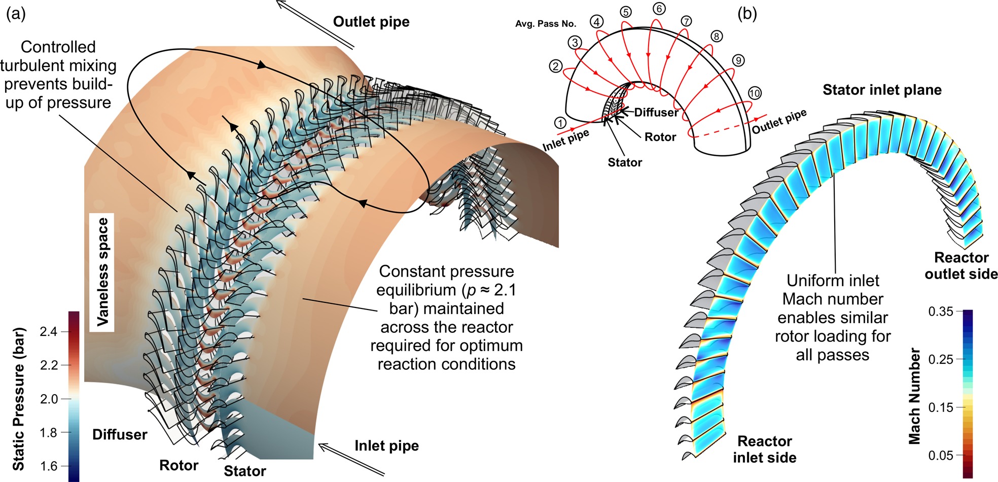
The advantage of using the unique open-volume vaneless-space is that it guarantees that a nearly constant pressure equilibrium is maintained across the reactor (see Figure 9a) as a result of the circumferential communication of pressure waves. The pressure level can be controlled with valves in the pipes. Within the open-volume vaneless space the flow naturally self-regulates in order to maintain well defined passes with straight and parallel streamlines (see Figure 8a). Therefore, this must be reflected by uniform pressure, which is a key characteristic defining the robustness of the concept.
From inlet to outlet, the increasing fluid temperature drives the density to decrease (by ∼35%) without an associated change in pressure. The nature of the open-volume vaneless space allows the streamtubes to naturally expand in response to this density reduction. Since mass is conserved, this streamtube expansion aids in maintaining an almost uniform inlet Mach number and flow coefficient across the reactor despite the density changes (see Figures 9b and 10c). Accompanied with this, Figure 10b illustrates that a similar stator blade loading profile is sustained for all passes, once again indicating well conditioned flow for all passes and therefore highlighting the robustness of the concept. The stator is designed with a thick leading edge to provide tolerance to incidence variations. This ensures that the necessary tangential velocity is presented to the rotor despite minor distortions to the flowfield at the stator inlet (see Figure 10b).
Figure 10.
Time-averaged (URANS): (a) Mach number at mid-span across a linearised turbo-reactor view (b) isentropic Mach number M isentropic ( ϕ = ( V x / U ) ) h r , 0
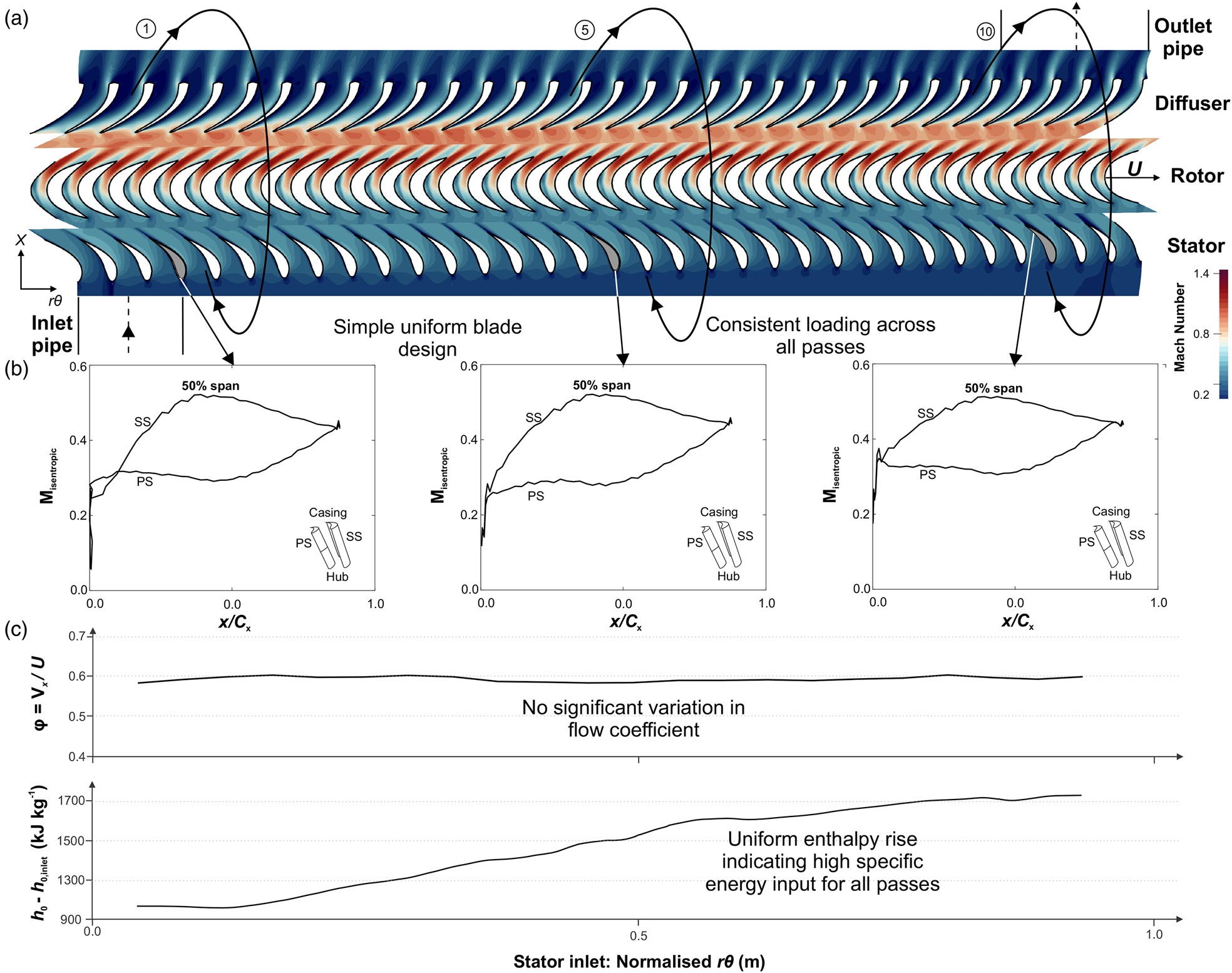
The rotor stage loading coefficient is a direct function of flow coefficient and the stator exit flow angle (which can be inferred from stator blade loading profiles shown in Figure 10b). Therefore it has been demonstrated that despite density variations, the robust concept enables a simple, circumferentially uniform blade profile and inner/outer casing design to be applied whilst sustaining a high level of specific enthalpy input across all rotor stages (see Figure 10c).
For true chemically reacting flow, the gas composition changes (during cracking) from inlet to outlet, which augments the temperature-driven density reduction across the turbo-reactor. This is reflected by a decrease in the Reynolds number from 200,000 (inlet) to 50,000 (outlet). Despite this, simulations (not included here for brevity) have indicated that the dependence of the aerothermal flowfield on the Reynolds number is relatively weak within this range. Importantly, the change in the rotor blade loading (work input) and dissipation rate (mixing) for these two Reynolds numbers are within a few percent.
If necessary, it is possible to circumferentially vary the blade pitch of the stationary blade rows to compensate for the effects of density and gas property variations due to the reaction (not modelled) on other non-dimensional groups (e.g., Mach number). This would ensure that the blade loading (and hence exit flow angle) is uniform for all passes by maintaining a constant passage mass flow rate. Therefore, a high-level of specific energy input can be imparted across the turbo-reactor. However even with a uniform design, the robust open-volume space should partially tolerate these variations through a natural streamtube self-adjustment.
Improving process quality: potential to reduce coke formation and deposition
Figure 11 illustrates that the new turbo-reactor provides the necessary conditions to potentially reduce coke formation and deposition. This is achieved through an order of magnitude higher average surface shear stresses (due to several times higher throughflow speeds, see Figure 11a), a lower wall metal temperature (by ∼200°C shown in Figure 11) and fluid–wall temperature gradient, in addition to 10× shorter residence times.
Figure 11.
Factors affecting coke deposition in conventional reaction tubes (adapted from Gao et al. (2009); Niaei et al. (2002)) and the turbo-reactor: (a) gas speed (b) wall temperature and fluid-wall temperature gradient.
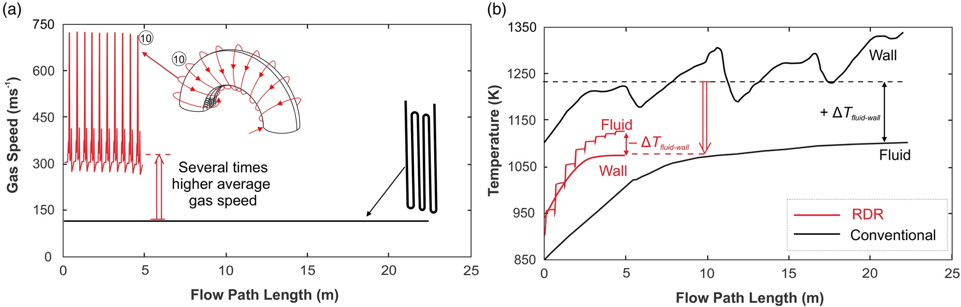
In sate-of-the-art conventional technology, a 60% reduction in the coking rate can be achieved by decreasing the tube metal temperature by 60°C (Vandewalle et al., 2017). This is considered a significant technological improvement. Therefore, a 200°C lower wall metal temperature in the RDR could lead to an order of magnitude reduction in the rate of coke deposition, indicating a potential step-change advancement in process quality. Consequently, this would lead to an increase in the plant availability and turbo-reactor lifetime, in addition to lower operating and maintenance costs. In contrast with 3-D internally ribbed radiant coil technologies in conventional reaction tubes, the improved coking rate is accomplished whilst avoiding large pressure losses, therefore mitigating any major losses to the olefin selectivities.
Controllability: tailoring the specific work input during operation
During plant operation, the level of specific enthalpy imparted into the working fluid needs to be tailored in order to maximise the yield (see Figure 1) depending on the real-time reaction dynamics and a priori modelling uncertainties. Furthermore, control of the enthalpy input and temperature distributions is vital in order to account for feedstock variability and flexibility (e.g., ethane, naphtha, butane, propane, bio-feeds, etc.), as well as to tailor the relative mass fractions of the products in the output stream depending on market price, customer requirements, and different downstream chemical processes.
The turbo-reactor offers the operational flexibility and controllability to produce relatively large changes in work input by performing only minor perturbations to the rotational speed. Figure 12 shows the envelopes of rotor blade loading and enthalpy rise across the machine resulting from a rotational speed variation around the nominal design value
Figure 12.
Operational envelopes (URANS) resulting from rotational speed perturbations Ω design ± 5 % Δ h 0 , r h 0 , inlet
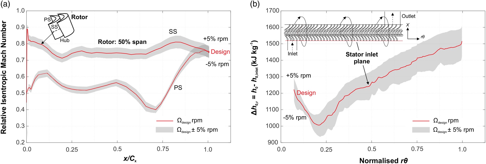
Figure 12 indicates that each stage successfully responds (almost linearly) to the change in rotational speed. Compared with non-dimensional similarity analysis i.e.,
Figure 13 summarises how the new turbo-reactor addresses many of the inherent limitations of a conventional furnace using an efficient and highly compact means of energy input into the working fluid.
Conclusions
This paper has introduced a novel concept aiming to replace the radiant section of a hydrocarbon cracking plant with a new turbo-reactor. The root of all the advantages of the RDR is in the replacement of the energy-input mechanism for the endothermic reaction from (indirect) surface heat exchange to direct mechanical energy transfer through a set of rotating blades. This paves the way to potentially decarbonise a highly energy-intensive, high-temperature industrial process by direct renewable electrification, as well as providing substantial improvements to the quality of the overall cracking process.
The turbo-reactor has the potential to remove the most fundamental limitations of the process, enabling a controllable and selective mechanism to generate the chemical reactions. Firstly, the residence time-scale for this process is up to an order of magnitude shorter than that of a conventional furnace, which provides a substantial improvement to the product yield and selectivity. This is enabled by supersonic throughflow speeds and impulse rotor blading, therefore enabling short time- and length-scale energy transfer and transformation processes. This includes an ultra-high loading rotor and a shock system in the diffuser. Secondly, a lower average wall temperature and a higher surface shear stress provide the necessary environment to potentially reduce coke formation and deposition, which is one of the most damaging side-effects of conventional cracking.
The numerical study presented has shown that the working principals of the elemental stage can be robustly realised in the full multi-stage environment. The necessary enthalpy input into the feedstock for the reaction can be provided regeneratively using only a single rotor with a short shaft, resulting a compact, low-cost reactor 500 times smaller than a conventional radiant furnace.
The robust unique open-volume vaneless space allows the rotor loading for each stage to be naturally de-sensitised to density variations, despite the application of a simple, uniform blade profile and inner/outer casing design (i.e., the distance between hub and casing is almost constant).
Intercommunication between the streamtubes, mediated by pressure waves propagating within the open-volume, guarantees an almost constant pressure equilibrium is maintained across the reactor as is required by the reaction. In conjunction with this, numerical simulations indicate that the intense turbulent mixing process is sufficient to further suppress a build-up of pressure within the non-bladed reactor space. Downstream of the mixing zone, the Reynolds number is very low which allows a rapid recovery of the flow to a well-conditioned state.
In spite of the challenges of the high relative Mach number design, it has been demonstrated that the turbo-reactor is able to respond to variations in rotational speed almost linearly and without deviating radically from the simple and ideal similarity rule. This indicates that sufficient speed-controllability is possible during operation. As a result, this increases the potential to perform online yield-tailoring to account for uncertainties in the reaction dynamics and feedstock variability and flexibility, as well as tailor the product yields depending on market price and customer requirements. This can be achieved by exploiting relatively large changes in specific energy imparted into the fluid resulting from only minor rotational speed perturbations.
Nomenclature
Symbols
axial chord length, m
specific kinetic energy, J kg−1
stagnation enthalpy, J kg−1
isentropic Mach number
static pressure, Pa
stagnation pressure, Pa
stagnation temperature, K
blade tip speed, m s−1
internal energy, J kg−1
axial velocity, m s−1
flow coefficient
work/loading coefficient
Acronyms