
Introduction
Motivation and background
Decarbonisation of hard-to-abate high-temperature endothermic chemical reaction processes, such as steam cracking of hydrocarbons, ethylene dichloride cracking, plastic recycling, hydrogen production through steam methane reformation (SMR), and ammonia decomposition, is a significant challenge of this decade (Thiel and Stark, 2021). These processes are essential components of large-scale global industries. For example, the hydrocarbon cracking market was recently valued at $240 billion, with a global annual capacity of 400 million tons per annum (Mtpa) (Bender, 2014). This is expected to grow to $350 billion, with a capacity of 600 Mtpa, by 2030. Furthermore, with the rapidly growing support for low-carbon hydrogen and ammonia for transport, industry, energy storage, and power generation, it is expected that their demand will increase exponentially, potentially reaching to 200 Mtpa by 2030, with a market value of $320 billion (IEA, 2022).
The primary challenge is that large-scale energy-intensive sectors (e.g., chemical/petrochemicals steel, and cement) account for almost 20% of global
Figure 1.
A schematic analysis of the energy transfer mechanism in a surface heat exchanger against that in the turbo-reactor.

Heavy industry can be transformed radically by exploiting the complex flow physics and controllable energy conversion processes possible within a turbomachine. This novel turbomachine, known as the RotoDynamic Reactor (RDR) or turbo-reactor, works on the principle of directly imparting mechanical energy to the working fluid supplied by a renewably powered electric motor as the mechanical driver (Rubini et al., 2021; Coolbrook Oy, 2022). As a result, Figure 1 demonstrates that the turbo-reactor can significantly increase power density by up to two orders of magnitude compared to a surface heat exchanger, leading to a reduced plant footprint, as well as lower capital, operating, and maintenance costs. This is achieved by converting almost all of the imparted mechanical energy into internal energy, rather than compressing the gas as is done in a compressor (which is another example of an energy-imparting machine). Therefore, high working fluid temperatures of up to
Figures 2 and 3 highlight the significant role of the RDR in decarbonising a diverse set of high-temperature endothermic reaction processes for the production of high-value commodity chemicals in the chemical industry, such as steam cracking, thermochemical plastic waste recycling, SMR for hydrogen production, and ammonia decomposition for hydrogen recovery. Alternative strategies to decarbonise these sectors include hydrogen-fired (Weydahl et al., 2013) or electric furnaces (Delikonstantis et al., 2019), but these suffer from large thermal resistances that hinder energy transfer (Venkataraman et al., 2003), low power density, and non-uniform temperature profiles within the tubes, all of which can degrade the efficiency of the process. Furthermore, there are additional challenges related to scalability at high temperatures for electric furnaces and low energy conversion efficiency


Objectives of this study
This first-of-its-kind paper demonstrates the applicability of the RDR for decarbonising a wide range of endothermic reactions within the chemical industry (see Figure 3). This study confirms the robustness and controllability of the system subjected to different feedstocks, variable reaction states, and a range of operating points. A broad spectrum of operating states is generated by harnessing variations in thermophysical/thermochemical fluid properties corresponding to different feedstocks (e.g., n-hexane, methane, etc.) and reaction progress states. The RDR is shown to be resilient and flexible, and energy can be effectively imparted and dissipated despite using a fixed stage design and boundary conditions.
The turbo-reactor: direct energy transfer for endothermic chemical reactions
Controllable elemental stage design for ultra-high power density energy input
The turbo-reactor concept and detailed design have been developed over many years of collaboration with Coolbrook Oy (2022) and are based on the original patent of Bushuev (2016). This new machine unlocks a radically new design space for high-power-density energy-imparting machines, as shown in Figures 2 and 4. Figure 4 compares the single-stage constant speed
For low molecular weight fluids, an ultra-high loading coefficient of up to 8.0 is possible (see Figure 4b). This is more an order of magnitude higher than that of a typical axial compressor, minimising the number of stages required for heating. Figure 4b indicates that the work coefficient increases approximately linearly with the flow coefficient, before turning to the vertical due to feed-composition-dependent choking limitations.
Within the choking limits of the working fluid, the RDR can leverage very high relative Mach numbers
Since there is no requirement to support a global adverse pressure gradient, Figure 4c illustrates that the onset condition for violent dynamic system instability is circumvented as
Figure 4.
A comparison between an axial compressor and turbo-reactor (both energy imparting machines), showing (a) the primary objectives, (b) the single-stage flow coefficient ϕ ψ ϕ C ψ TS

In a multistage environment, the flow must be reconditioned before the next rotor row. A stator vane is used to rapidly accelerate the flow to help it recover before entering the downstream row and to provide the necessary high Mach number with a large negative swirl angle (to the rotor). The favourable pressure gradient attenuates residual flow non-uniformities from the upstream mixing process, ensuring high performance across the multistage architecture (Karefyllidis et al., 2023).
Addressing the limitations of surface heat exchange
Compared to radiant furnaces, the RDR provides a fundamental advantage: mechanical energy is directly transferred into the fluid, making it the hottest part of the system. This is in contrast to furnaces, where the walls are the hottest part of the system due to the heat transfer process. This inherent feature of volumetric energy addition bypasses two key challenges encountered in radiant coils. First, the heat transfer area requirement is avoided, allowing a significantly shorter gas path (see Figure 1). Reaction selectivity is a function of residence time; therefore, the primary product yield can be increased.
Second, as indicated in Figure 1, the thermal and velocity boundary layers within the tubes are thick and mismatched. As a result, the majority of the fluid’s mass is concentrated at the centre, but the highest temperature is at the surface. This results in coke deposition on the walls due to high metal temperatures (for hydrocarbon feeds) and overcracking due to nonhomogeneous reaction progress. By avoiding these limitations, the RDR enables a more homogeneous and efficient reaction for all chemical processes, as well as lower coking rates for hydrocarbon-based feeds.
Fine-tuned control of the endothermic reaction dynamics
For high-temperature endothermic chemical reactions, where the enthalpy of reaction
Steam cracking: transforming heavy hydrocarbons into higher-value olefins such as ethylene
Thermochemical recycling of mixed plastic waste (Kusenberg et al., 2022): decomposing pyrolysis oil (PyOil) back into virgin-quality olefins (see Figure 3). PyOil is converted to olefins using the same process mentioned above (see 1.).
Steam methane reforming: the RDR is used to produce syngas
Ammonia
The objective of the non-reacting, ultra-fast preheating section
Once preheating is complete and the gas mixture is at the reaction activation temperature, the vapour enters the reaction zone where the turbo-reactor provides a tailored temperature profile based on the application-specific reaction dynamics (see Figure 2). This is achieved using a non-uniform axial distribution for the interstage vaneless space length (see Figure 2). For each stage, the axial dimension depends on the local heat of reaction, which is a function of the thermochemical state.
Numerical methodology
In the following sections, the versatility of the turbo-reactor will be demonstrated in its ability to operate effectively across a wide range of feedstocks and reaction conditions for various chemical processes powered by the RDR. The basic requirements for each process, based on the design of the datum stage, are summarised in Table 1. To evaluate the performance of the machine under these varying conditions without relying on computationally intensive reacting flow simulations, a framework has been developed to decouple the aerodynamics and chemical kinetics. This is introduced in the next section.
Table 1.
Approximate preliminary requirements for the preheating and reaction zones based on the datum stage.
A decoupled framework for evaluating the effects of chemistry on aerothermal performance
A low-order approach is taken to decouple computational fluid dynamic (CFD) simulations and chemical kinetics. This is summarised in Figure 5 and can be explained as follows. Offline, 1-D detailed kinetic simulations are conducted for steam cracking (of an n-hexane and ethane feed), SMR, and ammonia decomposition reactions across a broad temperature range
Figure 5.
(Left) The methodology for constructing performance maps of the RDR for a broad range of chemical processes and reaction states and (Right) temperature-dependent variations in thermophysical properties, speed of sound, and non-dimensional choking mass flow rate w.r.t. reaction progress in the range 150–1,000°C.

The impact of the chemical reaction is effectively lumped into changes in the fluid properties, with four variables forming the parameter space: static temperature T, heat capacity ratio
where
Block (1): 1-D chemical kinetic modelling
For each feedstock and chemical process illustrated in Block (1) of Figure 5, a chemical reaction mechanism is automatically generated using rmg-py (Gao et al., 2016). This includes both gas-phase reactions and heterogeneous surface-phase (catalytic) reactions. An in-house 1-D reactor model, built on top of a plug-flow reactor (PFR) model and a stiff ordinary differential equation solver within cantera (Goodwin et al., 2022), is used to approximate the enthalpy supplied by the rotor separated by user-defined time intervals representing the residence time per stage. Both ammonia decomposition and SMR require catalysts. For both, the surface-area-to-volume ratio is set to
For each reaction, the validity of the semi-perfect gas assumption was analysed. The Redlich–Kwong real gas equation of state was used to simulate the gas mixtures at the relevant operating points. For almost all regimes, the compressibility factor Z and fugacity coefficient
Block (2): sampling the fluid property space
The parameter space is formed by randomly sampling T,
Block (3): 3-D steady non-reacting RANS CFD modelling
To evaluate aerothermal performance, 500× steady three-dimensional, non-reacting RANS calculations using a single stage were performed for each sample in the parameter space (see Block (3) in Figure 5). This was achieved using the flow solver tblock (Denton, 1983, 1986, 1992) with a mixing-length turbulence treatment. The mixing length-scale is tuned on a block-basis and is set by the turbulent length scale calculated from high-fidelity LES. The computational setup, which employed a simplified computational domain and numerical treatment, allowed hundreds of CFD simulations to be run within a few hours. To assess mesh independence, three grades of mesh density were simulated. The mass-averaged flow coefficient, stage loading coefficient, and rotor exit Mach number error were within 0.7%, 1.9%, and 2.0%, respectively. This gives us confidence in the trends presented in the following sections.
Although the mesh is relatively coarse and the turbulence modelling relatively simple, it is emphasised that the main objective is to determine qualitative trends rather than absolute values. Moreover, the main quantity of interest is the bulk work coefficient, which is found to be less sensitive to turbulence modelling and mesh density for the impulse-type blades used here.
Robustness of the turbo-reactor concept to feed variability
This paper presents the first instance in turbomachinery in which the flow is reacting across the majority of the gas path length. This results in significant variations in the thermophysical fluid properties from inlet to outlet. These changes cover a broad range of molecular weights; therefore, leading to reaction-dependent variations on turbomachinery performance, more specifically, due to changes in the gas dynamics (
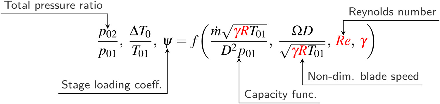
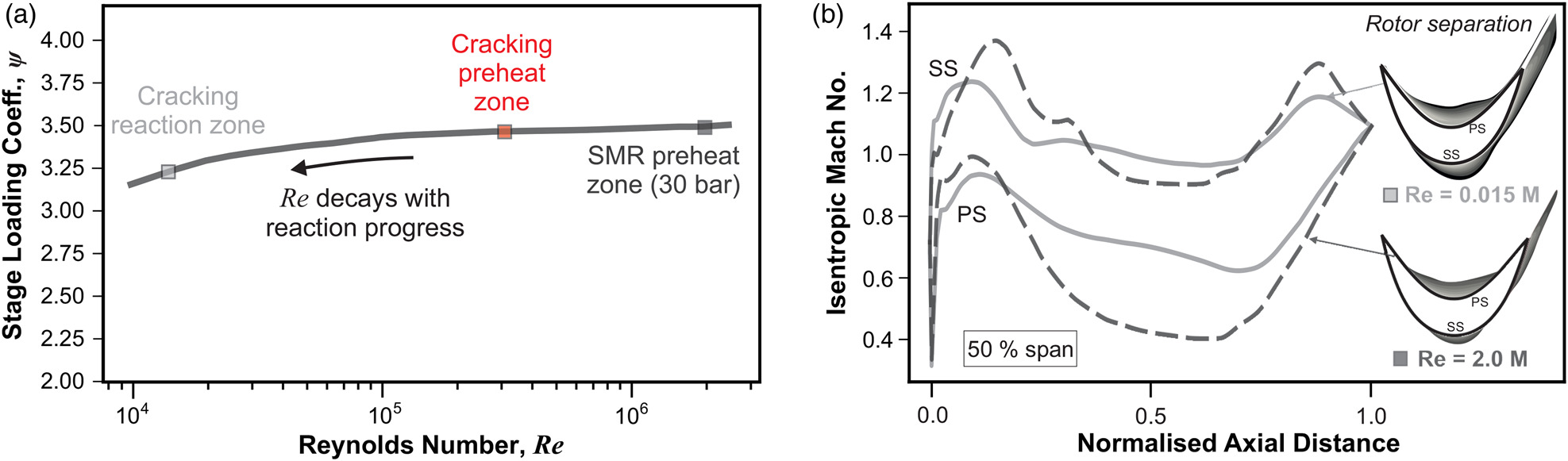
Influence of Reynolds number on aerodynamic performance
The Reynolds number
Aerothermal performance maps covering a wide operating range
This section demonstrates the applicability of using a turbomachine for four different chemical processes using a uniform stage design, fixed annulus flow area, and fixed boundary conditions. These conditions include a fixed imposed pressure ratio
Figure 7.
Aerothermal performance maps showcasing the reaction-progress trajectories with thick solid lines for four applications of the turbo-reactor (for a fixed Re = 100,000 and pressure ratio p exit / p 0 , in = 0.98

Each thick solid line indicated in Figure 7 represents the trajectory through non-dimensional parameter space using decoupled detailed 1-D kinetic calculations. This detailed chemical analysis is performed independently, and the results are superimposed on the performance maps. These lines effectively illustrate how aerothermal performance varies along the streamwise direction across a multistage machine for each chemical process. For all reactions, the imposed pressure ratio is fixed; therefore, the Mach number decays across the multistage machine. Since density decreases and the flow area is fixed, this is accompanied by an increase in the flow coefficient toward the rear of the machine. Therefore, the stage loading is higher near reaction completion. At the beginning of the reaction, the feeds are initially separated in the non-dimensional parameter space (see Figure 7). However, as the reactions progress, they all converge toward the higher loading region.
More generally, two insights can be gained from the response of the performance metrics shown in Figure 7. First, the ratio of specific heats has a relatively small impact on the stage loading. Secondly, the dominant parameters driving changes in flow physics are the non-dimensional blade speed and flow coefficient. The non-dimensional blade speed is inversely proportional to the speed of sound (see Figure 5 and Equation 1) and varies by almost a factor of 4.5, whilst the flow coefficient, which sets the velocity triangles, varies by almost a factor of 2 (due to the density variation). The stage loading coefficient does not respond significantly, with a maximum deviation of 15%, illustrating the robustness of the turbo-reactor despite the use of a fixed elemental stage. This margin can be further reduced by adjusting the delivery pressure and modifying the flow area to match the flow coefficient and the restore the velocity triangles. Since there is no onset condition for violent system instability (see Figure 4c), the machine can provide a high enthalpy input over a broad range of reaction and operating states.
Parameter space boundaries: extremes of the Mach number regime
Two extreme Mach number regimes, covering a wide range of feed molecular weights (2.0–86.0 g mol−1) and hence the speeds of sound (280–1,150 ms−1), are selected from the parameter space shown in Figure 7 and are compared in more detail in Figure 8. The low Mach number regime corresponds to an ammonia feed toward reaction completion, and the high Mach number regime corresponds to an n-hexane feed before the reaction starts. The first case represents a front stage of the machine, which is capacity-limiting due to the low speed of sound (see Figure 5 (Right)), and the second case represents a rear stage. The high Mach number case (see Figure 8 (Right)) is presented to illustrate the robustness of the flow at off-design regimes. However, in practice, the mismatched velocity triangles can be partially corrected by adjusting the delivery pressure to accommodate a higher mass flow rate, increasing the annulus flow area, and/or increasing the throat area to raise the swallowing capacity near the choke point.
Figure 8.
Comparison of the midspan relative Mach number distribution at two “extreme” corners of the parameter space where the fluid properties and local gas composition lead to two polar speed of sound regimes.
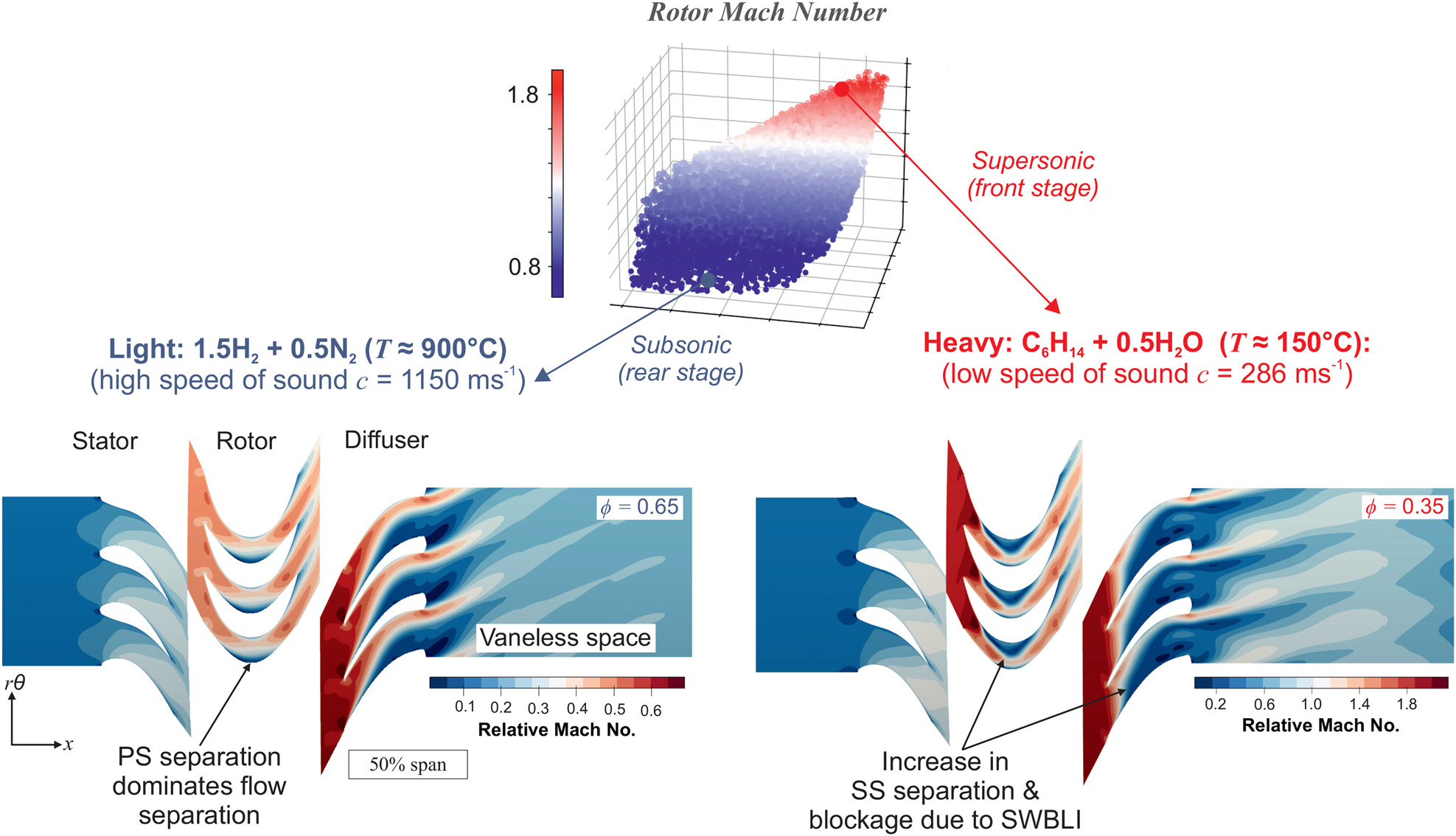
Figure 8 provides three key insights into the flow physics of the system. First, within the rotor, the low Mach number case is mainly affected by PS separation and blockage, whereas for the high Mach number case, an increased positive incidence angle results in a higher level of SS separation contaminating the flowfield. This is because (I) the flow coefficient drops by almost a factor of 2 for the high Mach number case (II) the Mach number is supersonic, making the flow sensitive to small changes in incidence
Second, the gas mixture in the low Mach number regime (Figure 8 (Left)) consists of 70% hydrogen on a mole basis. As hydrogen has a low molecular weight and hence a high speed of sound, it can accommodate a higher flow coefficient at a given pressure ratio and a fixed annulus area. This allows for a greater change in tangential velocity whilst avoiding the SWBLI in the rotor, resulting in higher stage loading (see Figure 8). As the flow is far below the choking limit, an even higher flow coefficient can be achieved by increasing the delivery pressure (see Figure 4b). Therefore, it is evident that the local fluid properties (set by the local composition state) have a significant influence on the operating range, compressibility, and loading capability for a fixed geometry. With the current datum design, the operating range of the high molecular weight n-hexane feed (Figure 8 (Right)) is more restricted, and the
Finally, the results presented demonstrate that the RDR can still achieve a reasonably high level of specific energy input
A breakdown of the energy conversion mechanisms
Once the kinetic energy (KE) has been absorbed by the flow through the rotor, it must eventually dissipate into internal energy u within the diffuser and vaneless space. In some configurations of the machine, such as the ultra-fast gas preheating zone before the reaction starts, the vaneless space can be removed, and the majority of the energy dissipation occurs every 2–4 stages. In contrast, for a gas mixture undergoing reactions, it is more optimal to dissipate the mechanical energy at every stage to repeatedly balance and compensate for the drop in temperature caused by the reaction.
A well-designed energy transformation system aims to convert kinetic energy into internal energy over the minimum possible time scale, typically less than
Figure 9 illustrates an approximate breakdown of the energy conversion mechanisms at the two flow regimes shown earlier in Figure 8 above. The energy conversion breakdown is determined by integrating the viscous dissipation rate
Figure 9.
A breakdown of kinetic energy (KE) to internal energy ( Δ u = c v Δ T )

Equation 3 is used to calculate the entropic portion
Figure 9 illustrates the differences in the energy conversion mechanisms for two feeds at different reaction states. In the subsonic case (i.e., high-temperature decomposed ammonia), isentropic energy conversion dominates since the flow in the blade passage is more attached. For the supersonic case, there is still a contribution from isentropic pressure rise, but the contribution is smaller, and the mechanism is dominated by pressure rise due to the isentropic component of the shockwave action rather than diffusion induced by changes in the effective flow area.
In both cases, the energy conversion due to trailing edge (TE) mixing is large since the TE is thick (42% of the blade pitch), blunt and square. In the supersonic case, this energy conversion source is well over 50% of the total energy conversion. This is significantly higher than the subsonic case as TE mixing loss scales with Mach number Denton and Xu (1990). In the supersonic case, the entropy generated through the shock is relatively small, meaning that the direct impact of the shock is minor. However, there is a substantial indirect impact from the shockwave due to shock-induced boundary layer separation. This significantly enhances boundary layer dissipation as well as downstream mixing.
This analysis shows that, despite variations in the incoming dynamic head over a wide range of operating points and feeds, almost 60% of the rotor exit kinetic energy can be dissipated into internal energy over a short distance (<50 mm). In different regimes, the flow self-adjusts the contributions from each conversion mechanism to match the downstream boundary condition. Future work will investigate the energy conversion mechanisms in more detail.
Summary and conclusions
This study has demonstrated the feasibility of using an electric-motor-driven turbomachine to mitigate carbon emissions and improve the operability, controllability, and reaction performance of four crucial energy-intensive endothermic reaction processes. The numerical investigation presented in this paper has revealed several key design characteristics of the concept summarised in Figure 10, which are as follows:
It has been shown that a universal stage design philosophy can be used for a wide range of feeds and reaction states. The specific energy input remains relatively high over a wide range of conditions. Since the collection of molecular weights covered is extensive, many other relevant chemical and non-chemical processes should fall within this range.
The robustness of the turbomachine has been successfully demonstrated over a wide range of operating and Mach number regimes by inducing operating point excursions through fluid property perturbations. The stage loading only dropped by 15% over a broad set of flow conditions, indicating the flexibility of the RDR. Additionally, the turbomachine showed a weak dependence on the Reynolds number, with only a 9% variation in the work coefficient over two orders of magnitude of the Reynolds number.
Without a requirement for pressure gain, the design restrictions of efficiency and system instability are no longer relevant. Therefore, a high level of incidence and separation can be endured, facilitating a high level of energy input and swallowing capacity over the operating range. The limits of the RDR are set only by choking (which is a restriction on the throughflow capacity of the machine) and not by system instability. Of course, local flow instability within certain blade rows may still occur.
Over a broad range of gas velocities and Mach numbers—corresponding to different feeds and reaction states—this work has shown that kinetic energy can be dissipated into internal energy (and static temperature rise) over an extremely short time scale of

Nomenclature
Symbols
b
true blade chord, m
speed of sound, m s−1
total-to-static pressure rise coefficient
cp
isobaric heat capacity, J kg−1 K−1
cv
isochoric heat capacity, J kg−1 K−1
h0
stagnation enthalpy, J kg−1
enthalpy of reaction, J kg−1
non-dimensional choking mass flow rate
p
static pressure, Pa
p0
stagnation pressure, Pa
R
specific gas constant, J kg−1 K−1
Reynolds number
Ṡvsic
viscous dissipation rate, W
T
static temperature, K
Δu
internal energy change, J kg−1
U
mean blade speed, m s−1
v
domain volume, m3
V
absolute velocity, ms−1
Vx
axial velocity, ms−1
heat capacity ratio
ζ
energy conversion coefficient
μ
dynamic viscosity, Pa s
stage loading/work coefficient
flow coefficient
τij
shear stress tensor, Pa