
Introduction
Gas turbine technology has improved over the last several decades. The greater efficiencies and advanced engine materials result in higher turbine operating temperatures which, in turn, negatively affect the lubricating oil circulating throughout the system (Gschwender et al., 2001). In fact, gas turbines produce the most severe turbine oil operating conditions, when compared to water and steam turbines, due to high sump temperatures and high hot-spot peaks (Novotny-Farkas et al., 2008; ASTM International, 2020a). Exposing lubricating oils to extreme temperatures results in the formation of solid deposits in the oil, or, more specifically, in coke formation. Coke deposits are insidious, black, solid, carbonaceous deposits formed as a result of oil oxidation and thermal breakdown at extreme engine temperatures (Gschwender et al., 2001; Exxon Mobil Corporation, 2016; Snyder et al., 2017). The formation of solid deposits greatly limits the oil’s ability to reduce wear and cool the turbine components. In addition, coke formation is a major cause of premature component failure; results in high maintenance costs and valves sticking; interferes with heat transfer from the parts to the oil; reduces oil flow rates; and clogs tubes and nozzles that spray lubricants on the bearing (Kauffman et al., 2000b; Novotny-Farkas et al., 2008; Snyder et al., 2017).
Since progress towards higher-efficiency turbines, and therefore higher operating temperatures, will continue, and since turbine operators want to extend the periods between maintenance as far as possible, gaining an understanding of the high-temperature oil degradation and solid deposit formation process is necessary. Although the search for answers is decades long, the existing investigations have not resulted in concrete solutions, and further research is still necessary. Several bench tests exist to evaluate an oil’s ability to resist oxidation and thermal degradation. However, most of the standardized tests used by oil manufacturers and other tests developed over time do not meet the temperatures or conditions experienced by the oils in operation. For example, the Rotating Pressure Vessel Oxidation Test (RPVOT) and Turbine Oil Stability Test (TOST), two ASTM standardized tests used by oil manufacturers, only reach temperatures of 150°C and 95°C, respectively (ASTM International, 2014, 2020b); on the other hand, according to previous studies, coke formation can occur at hotspots at more than 400°C in supply lines during operation or at 300°C in static oil films after engine shutdown (Kauffman et al., 2000b; Novotny-Farkas et al., 2008). There is therefore a need for a test rig that is able to test the oils under conditions that more closely resemble real-life turbine oil operating conditions that can lead to coke formation in lube oils. This paper presents the initial use of such an apparatus that was recently constructed at Texas A&M University (TAMU).
Provided first is a literature review that discusses lubricating oil composition, the oxidation and thermal decomposition process, and previous test rigs. A description of the new TAMU test rig and its components’ functions and pressure and temperature ratings follows. Finally, information on the initial tests and results obtained is included.
Literature review
Despite the need for a solution to the oil degradation problem that exists in several areas of industry, the available information about this phenomenon is limited. There is some information available, however, on the coking process, oxidation and the factors affecting it, and thermal breakdown of lubricating oils. The following subsections provide brief summaries.
Lubricating oil composition
Most engine oils are composed of a basestock or base oil (72–96%) that is formed by hydrocarbons and is commonly obtained through either the refining of crude oil or through synthetic formation, and an additive package (4–28%) (Pawlak, 2003). The base oil provides the fluid layer that separates moving surfaces, reduces friction, and removes heat and wear particles, while the additives enhance or create properties in the base oil (Prince, 2010). The base oil must be able to keep all the additives in solution at all times under normal operating conditions.
The American Petroleum Institute (API) classifies the base oil types into five groups. The base oils are mostly classified based on sulfur and saturate concentration and viscosity-index range. However, a more general description is provided here. Base oils in Groups I, II, and III are derived from crude oil and are therefore considered as mineral based. Group IV oils are polyalphaolefins (PAOs) only, which are chemically synthesized oils (Brown et al., 2010; Noria Corporation, 2012; Pirro et al., 2016). Group V base oils include all base stocks that do not fall under the other categories and include both mineral-based and synthetic oils.
Group I oils are made from traditional, simpler solvent refining techniques and are the least expensive, the least molecularly uniform, and have the lowest operating temperature range. Group II and III base oils are both produced by hydroprocessing (Pirro et al., 2016). They have better antioxidant properties, have a clearer color, and are more expensive when compared to Group I oils (Noria Corporation, 2012). Group III base oils are more refined and purer than those in Group II. Group IV includes the chemically synthesized PAOs and have “a unique combination of high temperature viscosity retention, low volatility, very low pour point, and a high degree of oxidation resistance” (Pirro et al., 2016). Finally, Group V base oils are also chemically engineered and include all oils that do not fall into the other groups. Like those in Group IV, they have several advantages over the base oils in the first three groups (Noria Corporation, 2012). The lines between these categories are becoming less clear as the refining processes evolve (Prince, 2010).
Additives are chemical compounds added to lubricating oils to impart specific properties, enhance already existing properties, or reduce the rate at which undesirable changes progress. Table 1 provides a summary of some of the most common additives and their main functions (Pirro et al., 2016). Although additives greatly improve the performance of lubricating oils, excessive amounts or unwanted interactions between additives may yield negative side effects. Oil manufacturers, therefore, search for the right balance and combination of base oils and additives to obtain the best results and must test for the negative side effects. Understanding the base stocks and additives available and how they interact with each other and matching their behavior with the machine’s needs and operating conditions is necessary to obtain the best performance (Pirro et al., 2016).
Table 1.
Common additives and their main functions.
Mechanism of coke formation
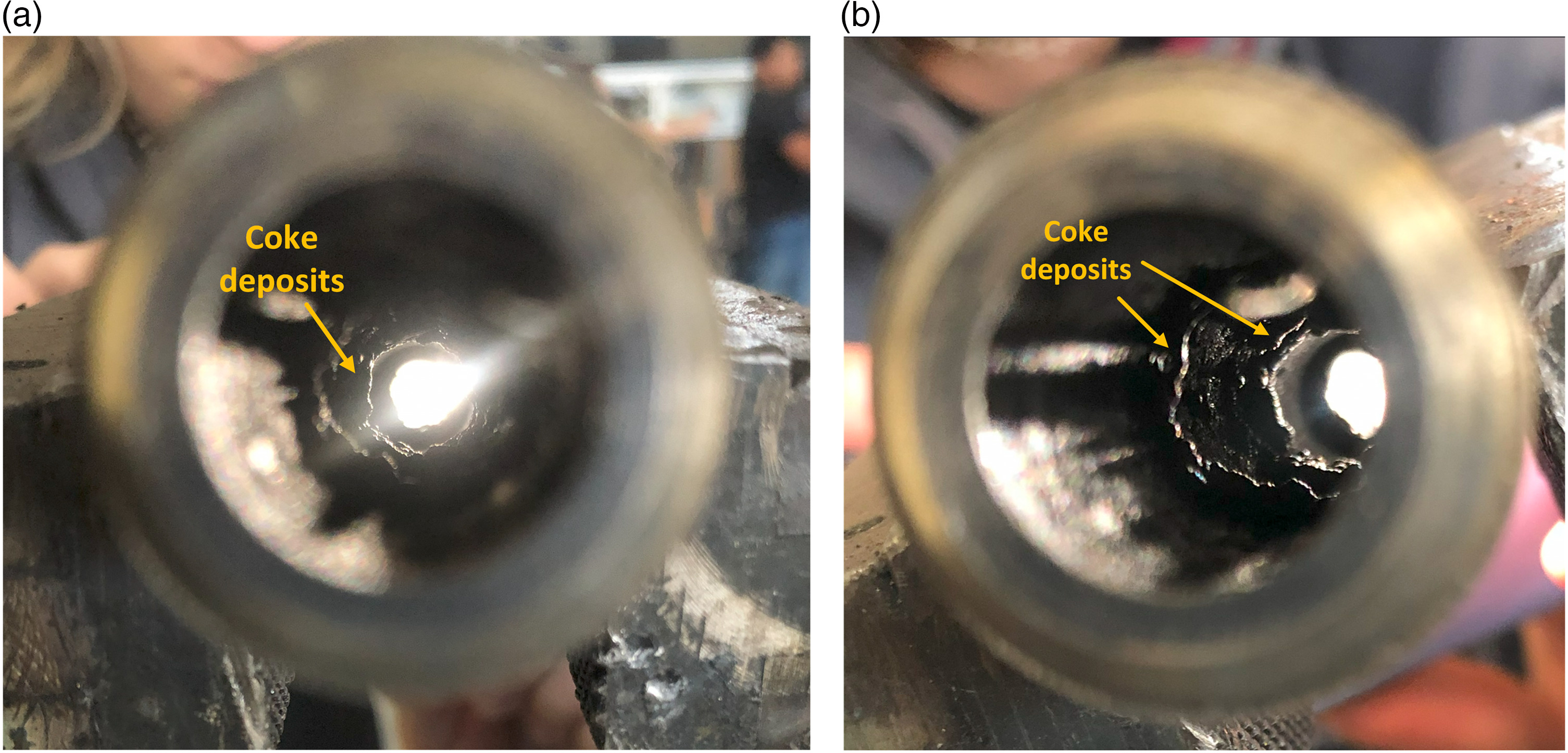
Coke is an insidious, black, solid, carbonaceous deposit that is formed from the degradation of lubricating oil at extremely high temperatures (Gschwender et al., 2001; Exxon Mobil Corporation, 2016). Figure 1 contains a picture of coke deposits produced in the authors' laboratory.
Figure 1.
Sample of coke deposits that accumulated on the flow path of a 1.43-cm inner diameter tube.
Kauffman et al. (2000b) described the oil degradation process for a thin layer of oil on a hot surface which is illustrated in Figure 2. The process is as follows: the antioxidants protect the base oil and delay the degradation process. They neutralize the highly reactive molecules in the oil, but, since each antioxidant molecule can only neutralize a basestock molecule once, the antioxidant reserves are depleted as time passes. More details on how they function are provided in subsequent sections. This protection continues until the ineffective antioxidant level, here defined as 10% of the original antioxidant package, is reached. The time at the high temperature required to reach the ineffective antioxidant level is called the induction time. Next, the basestock esters begin to polymerize and form intermediate oligomers that remain dissolved in the oil. Esters are molecules that are formed by the reaction of an alcohol with an acid, and they are the main components of synthetic oils (Szydywar, 1984). An oligomer is a type of polymer; unlike a polymer, however, it is made of only a few monomers (the basic units that form a polymer) and is, therefore, lighter. The oxidation is inhibited by the antioxidants at first but proceeds rapidly once they have been depleted. Weight loss in this stage also indicates that more-volatile molecules are also forming. In the third step, the polymers expand large enough to become insoluble within the lube oil, resulting in the initial deposits. The final step, in which the polymers turn into coke, does not require oxygen, but it speeds up the process.
Figure 2.
Oil degradation process of a thin layer of lubricating oil on a hot surface, adapted from Kauffman et al. (2000b).
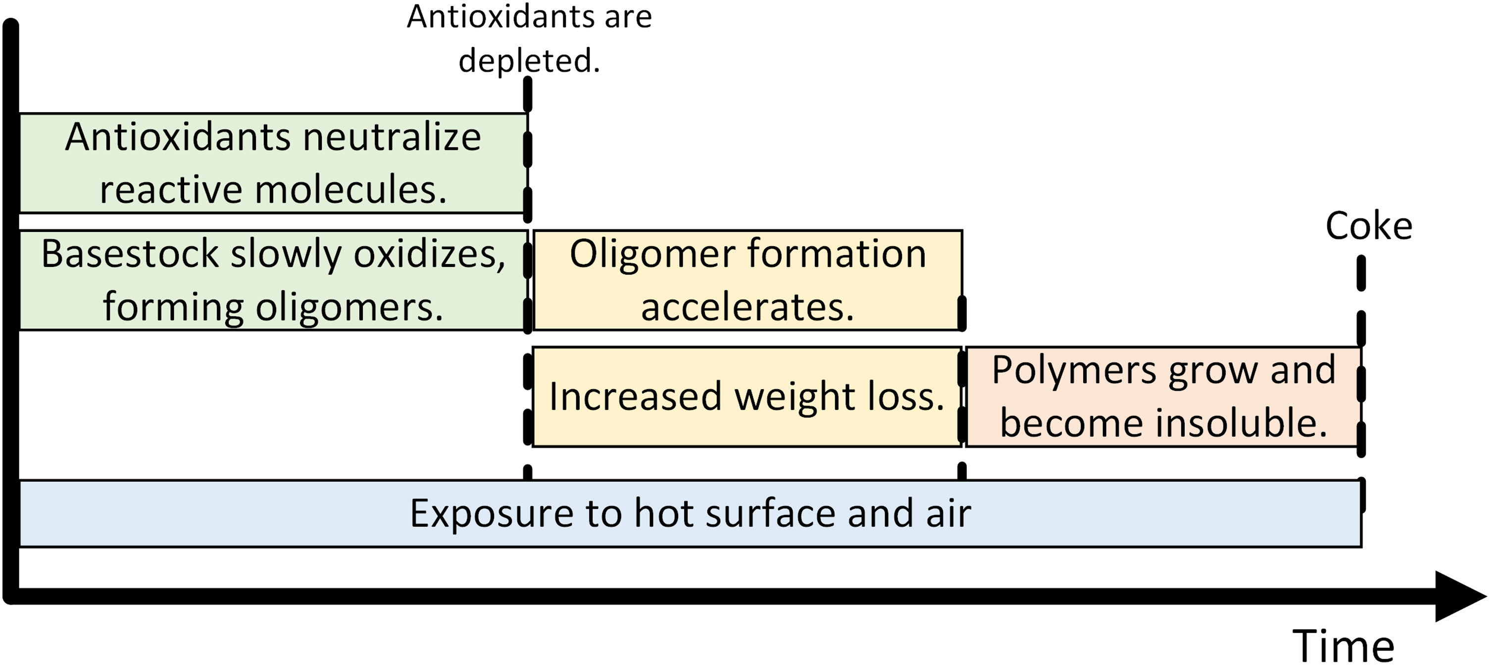
Kauffman et al. (2000b) also make several statements about the process that stand out. First, antioxidants delay the coke formation process. Second, although the addition of antioxidants increases induction time, it also increases the amount of deposit formed once coking takes place. Third, “if the time that a thin oil layer spends on a hot surface at elevated temperatures can be limited so that the antioxidant does not deplete completely, coking can be prevented” (Kauffman et al., 2000a). Oil choice (including antioxidant package choice) makes a difference on how long this time can be. Finally, the surface material does not affect the rate of antioxidant depletion, but it does affect the polymer and coke formation rate.
Oxidation
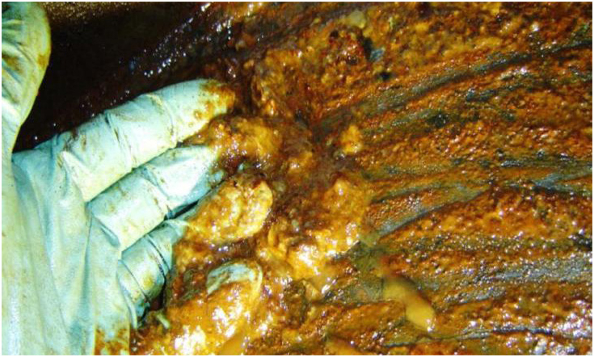
Many list oxidation as the main form of lubricant degradation (Naidu et al., 1986; Mousavi et al., 2006; Diaby et al., 2009); but, in the literature that discusses the oxidation of lubricating oils (as opposed to coke formation), sludge and varnish, rather than coke, are mentioned as the direct result of the oxidation process. Varnish is typically distinguished as a thin, insoluble, nonwipeable film deposit, with a cured, shiny appearance, whereas sludge is soft and tacky and can move about the system (Fitch and Gebarin, 2006). A picture of sludge accumulation is included in Figure 3. However, several papers, including the one discussed in the previous section, state that oxidation is an important part of the coke formation process and/or that antioxidants prevent coke formation (Chernojookov, 1929; Grigor’ev et al., 1977; Kauffman et al., 2000a,b; Gschwender et al., 2001; Yokoyama and Iwama, 2014; Miyata et al., 2015; Exxon Mobil Corporation, 2016; Pirro et al., 2016; Bardasz and Lamb, 2017). Pirro et al. (2016) provide an explanation to this seeming discrepancy: “In extreme cases, these deposits [sludge, varnish and lacquer] may be further oxidized to form hard, carbonaceous materials” (i.e., coke).
The general steps of oxidation and deposit formation are described below. These steps describe in more detail the process illustrated in Figure 2. Here, R represents a hydrocarbon and R· represents a hydrocarbon with a free radical. A free radical is formed when a covalent bond breaks and a single electron remains with each of the fragments, where free radicals are electrically neutral but are highly reactive because of their unpaired electrons (Schobert, 1990).
The initiation reactions involve the formation of free radicals (Chen and Hsu, 2003; Pawlak, 2003; Gatto et al., 2006; Mousavi et al., 2006; Diaby et al., 2009). Reactions 1, 2, and 3 show examples of reactions that lead to free radical formation.
Alkyl radicals (R·) in the lubricant react with the dissolved oxygen (O2) in the high-temperature air to produce peroxy radicals (ROO·) (Zerla and Moore, 1989; Chen and Hsu, 2003; Pawlak, 2003; Gatto et al., 2006; Mousavi et al., 2006; Diaby et al., 2009; Aguilar et al., 2010; Bardasz and Lamb, 2017).
The peroxy radicals react with additional hydrocarbon molecules to form hydroperoxides (ROOH) (Popovich and Hering, 1959; Bakunin and Parenago, 1992; Gatto et al., 2006; Diaby et al., 2009; Aguilar et al., 2010; Bardasz and Lamb, 2017) and additional alkyl radicals (Gatto et al., 2006; Bardasz and Lamb, 2017). This step (Reaction 5), along with Reaction 4, is called the propagation step (Chen and Hsu, 2003; Pawlak, 2003; Gatto et al., 2006; Diaby et al., 2009; Aguilar et al., 2010; Bardasz and Lamb, 2017).
Many chain-branching steps are possible based on the lubricant type and the temperature of the system (Gatto et al., 2006); some of these are shown in Reactions 6 through 8 (Mousavi et al., 2006; Diaby et al., 2009; Aguilar et al., 2010; Bardasz and Lamb, 2017).
The two reactions most relevant to sludge formation are the decomposition of the hydroperoxide to form low molecular weight (LMW) materials such as aldehydes and ketones (Popovich and Hering, 1959; Naidu et al., 1986; Zerla and Moore, 1989; Bakunin and Parenago, 1992; Chen and Hsu, 2003; Gatto et al., 2006; Mousavi et al., 2006; Diaby et al., 2009; Aguilar et al., 2010). Two of the most accepted mechanisms of their formation are shown in Reactions 9 and 10 (Gatto et al., 2006; Bardasz and Lamb, 2017).
The oxidation reactions also produce alcohols and acids (Popovich and Hering, 1959; Naidu et al., 1986; Zerla and Moore, 1989; Bakunin and Parenago, 1992; Chen and Hsu, 2003; Gatto et al., 2006; Mousavi et al., 2006; Diaby et al., 2009; Aguilar et al., 2010). The aldehydes, ketones, alcohols, and acids are called the primary oxidation products. Reaction 10 is an example of alcohol formation during oxidation. Reactions 7 and 8 show an alkoxy radical (RO·) and hydroxy radical (HO·) removing a hydrogen atom from another hydrocarbon and producing alcohols and water, respectively. In general, carboxylic acids are formed by the oxidation of ketones and aldehydes (Gatto et al., 2006).
Polymerization or condensation of the primary oxidation products leads to the formation of high molecular weight (HMW) materials which increase the viscosity and have a limited solubility in the un-oxidized components of the lubricant and therefore precipitate as lacquers, varnishes, or sludges (Popovich and Hering, 1959; Naidu et al., 1986; Zerla and Moore, 1989; Bakunin and Parenago, 1992; Chen and Hsu, 2003; Gatto et al., 2006; Mousavi et al., 2006; Diaby et al., 2009; Aguilar et al., 2010; Bardasz and Lamb, 2017). Recall that according to Pirro et al. (2016), these lacquers, varnishes, and sludges may be further oxidized to form coke in extreme conditions. The details of this final step are not readily available in the literature, however.
Aldol condensation reactions play a significant role in this step once high levels of aldehydes and ketones have been formed (Bakunin and Parenago, 1992; Gatto et al., 2006; Bardasz and Lamb, 2017). Aldol condensation reactions are studied in organic chemistry, and they are a useful way of joining together 2 carbon chains. Bakunin and Parenago (1992), however, state that aldol condensation reactions are unlikely, and name the Knoevenagel-type condensation reaction, a modification of the Aldol condensation reaction (Clayden et al., 2000) as a reasonable alternative.
Oxidation will gradually occur under mild operating conditions, but temperature is the primary catalyst of all oxidation reactions (Fitch and Gebarin, 2006; Severa et al., 2009). There is a rule of thumb that for every 10°C increase in operating temperature, the rate of oxidation doubles (Arrhenius Rate Rule) (Pawlak, 2003; Fitch and Gebarin, 2006; Pirro et al., 2016). Although Zerla and Moore (1989) state that a 10°C change in temperature at the temperatures they tested caused the induction time to change by approximately 1.5 times only.
Metallic elements present in the lubricating oil generally act as catalysts and speed up the degradation process. Iron, copper, lead, and aluminum in particular are described in the literature as oxidation catalysts (Zuidema, 1946; Popovich and Hering, 1959; Chen and Hsu, 2003; Fitch and Gebarin, 2006; Gatto et al., 2006; Diaby et al., 2009; Exxon Mobil Corporation, 2016). Although these metals are the ones typically mentioned in the literature, they “are probably no worse in their effect than several others which could act as catalysts, such as manganese, chromium, or vanadium, but they play a more important role because of their much greater prevalence” (Zuidema, 1946). The oxidation initiation reactions catalyzed by iron and copper are illustrated in Reactions 11 and 12 (Gatto et al., 2006; Bardasz and Lamb, 2017).
It is important to point out that, in general, oils can “tolerate” small amounts of catalysts without any significant negative effects, but once the catalyst concentration increases beyond a certain point, the increase in catalyst concentration will decrease the induction period; if the concentration increases even more, a point “where the system is again insensitive to further change in concentration” is reached again (Zuidema, 1946). Light and water may also act as oxidation catalysts (Chen and Hsu, 2003; Pawlak, 2003; Fitch and Gebarin, 2006; ASTM International, 2020a).
Antioxidants play an important role in preventing oxidation (Zuidema, 1946; Popovich and Hering, 1959; Pawlak, 2003; Gatto et al., 2006; Mousavi et al., 2006; Aguilar et al., 2010) and, therefore, deposit formation (Zerla and Moore, 1989; Kauffman et al., 2000a,b; Gatto et al., 2006). Antioxidants act in different ways to control the degradation of lubricants:
Radical scavengers (primary antioxidants) function to scavenge alkyl peroxy and alkoxy radicals before they can react with oil molecules in the propagation reactions (Pawlak, 2003; Gatto et al., 2006; Aguilar et al., 2010; Bardasz and Lamb, 2017); they prevent Reaction 5 from occurring and cause Reaction 13 to take place instead, where
Peroxide decomposers (secondary antioxidants) decompose the unstable alkyl hydroperoxides to the more stable alcohol form (Gatto et al., 2006; Mousavi et al., 2006; Aguilar et al., 2010; Bardasz and Lamb, 2017). They prevent initiation Reactions 11 and 12 and propagation Reactions 6, 7, and 8 from occurring (Gatto et al., 2006).
Metal deactivators behave as metal passivators to prevent catalytic effects that lead to oxidation initiation (Pawlak, 2003; Mousavi et al., 2006; Bardasz and Lamb, 2017).
There are tradeoffs to using antioxidants. First, if coke does form, a higher initial antioxidant level will likely produce a larger deposit amount than would be obtained with a lower level of antioxidants (Kauffman et al., 2000a,b; Gatto et al., 2006). For example, in their experiments, Kauffman et al. (2000b) found that antioxidant compounds were incorporated in the deposits that formed during testing and therefore increased the amount of coke formed. Furthermore, Gatto et al. (2006) state that sulfur compounds and alkylated diphenylamines, which are normally used as antioxidants, promote sludge and deposits. The former does so by “forming sulfur acid species that catalyze the condensation reactions”, and the latter by forming carbonyl compounds which are needed for the condensation reactions. Second, to meet the original equipment manufacturers’ requirements for turbine oils, oil developers use higher additive treat rates that, due to the limited solvency of synthetic base stocks and the vulnerable thermal stability of some antioxidants, can cause additive dropout, sludge, and varnish at early stages of use (Novotny-Farkas et al., 2008). Therefore, ideally, an oil should have an optimal ratio of the different kinds of antioxidants that have synergistic potential and lower the needed additive treat rates and consequently also lower the risk of additive dropout and deposit formation (Gatto et al., 2006; Novotny-Farkas et al., 2008). Finally, antioxidant additive components must have low volatility, good thermal stability, and adequate solubility in the basestock used (Novotny-Farkas et al., 2008).
Thermal decomposition
As mentioned by Pirro et al. (2016), thermal stability (as opposed to oxidation stability) is the ability of an oil to resist decomposition under prolonged exposure to high temperatures with minimal oxygen present. When compared to oxidation, significantly less information is found in the literature regarding thermal decomposition. Like in oxidation, there is an initial period during which the thermal degradation process is slow. Once the oil’s thermal stability point is reached, however, the hydrocarbon begins to thermally crack (Mathura, 2020). The small molecules that result either evaporate, leaving no deposit behind, or condense and undergo a dehydrogenation process that eventually leads to coke formation. Unlike oxidation, thermal degradation processes lead to a decrease in viscosity due to the cleaving of the molecules.
The oil can reach the temperatures required for thermal decomposition by coming into contact with a hot surface, due to adiabatic compression from entrained bubbles, or due to an electrostatic discharge. Machine surfaces with temperatures greater than 200°C result in thermal degradation, depending on the oil, and increasing temperatures beyond this value rapidly reduces oil life (Fitch and Gebarin, 2006; Mathura, 2020). Adiabatic compression from entrained bubbles occurs when air bubbles travel from low pressure to high pressure. The pressure change causes the bubble to implode which results in an “intense entrapment of the heat and extreme rise in temperature locally in the oil” (above 1,000°F may be reached) (Fitch and Gebarin, 2006). Pressure-induced dieseling (PID) is a special situation that occurs when fluids are aerated and high compression pressures are seen. The temperatures reached with PID can lead to microscopic ignition of the fuel-lean oil vapor/air mixtures. Electrostatic discharge is caused by the electrostatic charge generation and subsequent static discharging that causes temperature increases and thermal-oxidative oil degradation. Temperatures as high as 10,000 to 20,000°C may be reached (Fitch and Gebarin, 2006).
Previous test rigs
The test rigs that have been developed to study the oil degradation and coking phenomenon can be classified into three general categories: static oil, heated plate, and flowing oil experiments. The three basic categories include: (1) Static oil experiments where the oil sample is exposed to a high temperature, catalysts, and air or nitrogen; samples are removed at regular intervals or at the end of the test for analysis; (2) heated-plate experiments where the oil is in contact with a heated plate, and the plate is analyzed for deposit weight and appearance; and (3) flowing oil experiments where the heated oil flows through the system, and deposits are inspected at the end of the test. Over a dozen experiments may be found in the literature, and four of them are described below.
Penn State micro-oxidation test
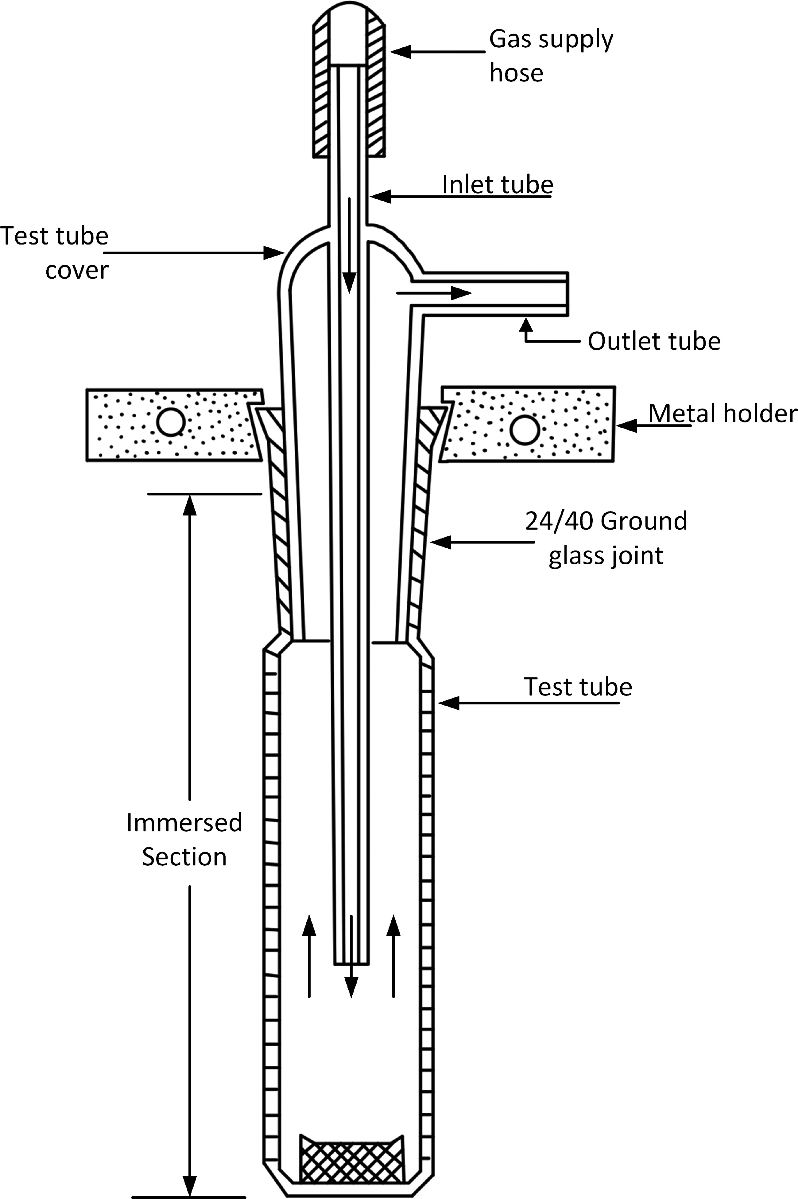
In this test, a cup made of low-carbon steel (designed so that the oil will form a thin film on the metal surface) is placed at the bottom of the reactor (glass tube) which is then immersed in a constant-temperature bath (Naidu et al., 1986). Note that the low-carbon steel is a catalyst for oxidation and polymerization reactions. Once the system is in equilibrium, the lubricant is injected into the cup. Air or nitrogen flows through the reactor for a specified amount of time (Kauffman et al., 2000a). When the test is finished, the cup is removed from the heating chamber, allowed to cool, and re-weighed to determine the weight of the remaining oil residue. The residues are then analyzed. Results are often reported as percent deposit of the oil injected (Zerla and Moore, 1989). Some authors have modified this test to improve repeatability and reduce test time and also developed less-costly alternatives (Zerla and Moore, 1989; Kauffman et al., 2000a). Figure 4 shows a sketch of the apparatus used.
Figure 4.
Penn State Micro Oxidation Test apparatus. Adapted with permission from Naidu et al. (1986). Copyright 1986 American Chemical Society.
Panel coker test
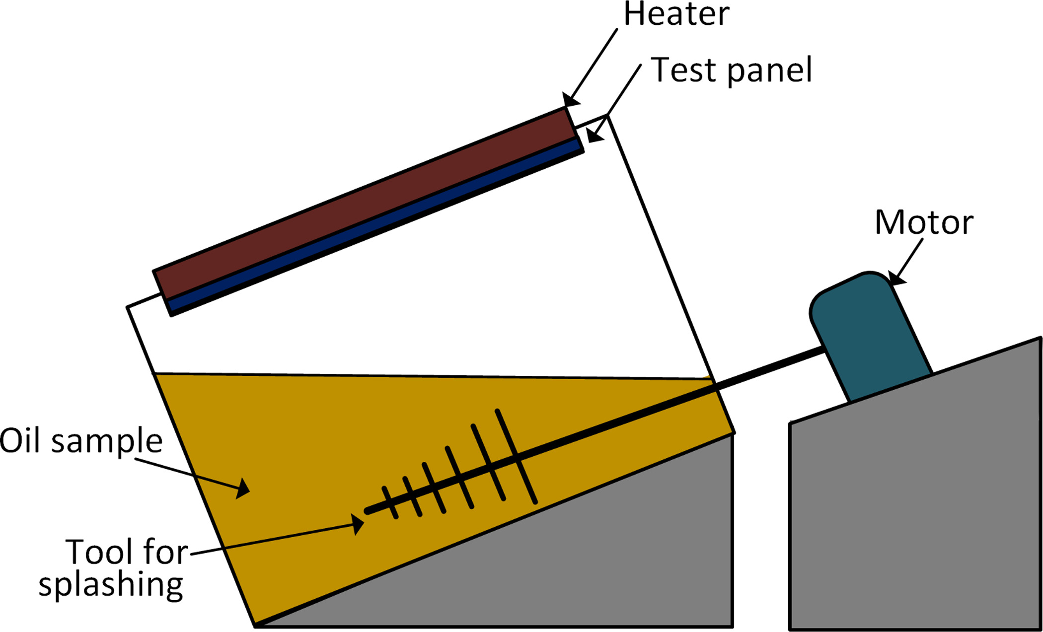
The Panel Coker Test (Kagaya and Ishikawa, 1984; Cazin et al., 1997; Yokoyama and Iwama, 2014), seen in Figure 5, consists of intermittently splashing the oil onto a heated, inclined test panel under a 15-second cycle operation and a 45-second shutdown (Kagaya and Ishikawa, 1984). The panel is kept at a constant temperature throughout the test, and it is placed inside a glass chamber in a humid air or other atmosphere. At the conclusion of the experiment, the nature and amount of the deposits formed are evaluated, and the oil is analyzed for degradation (Cazin et al., 1997).
Hot liquid process simulator
The hot liquid process simulator (HLPS) tests an “oil’s propensity to form deposits in a fully flooded region of the engine,” it simulates oil flowing through pressurized lines (Watkinson, 2003; Lansdown and Lee, 2010; Exxon Mobil Corporation, 2016). The apparatus, which is similar to a heat exchanger, is sold by SPL Alcor Petrolab. In this test, the flow, pressure, and target surface temperature are selected (Watkinson, 2003). Inlet and outlet temperatures as well as the axial profile of the surface temperature are recorded at different time intervals. As fouling occurs, the heat flow to the fluid decreases, resulting in a decrease in the outlet fluid temperature. The fouling resistance or fouling percentage versus time may be used to analyze coking propensity (Branson, 2016).
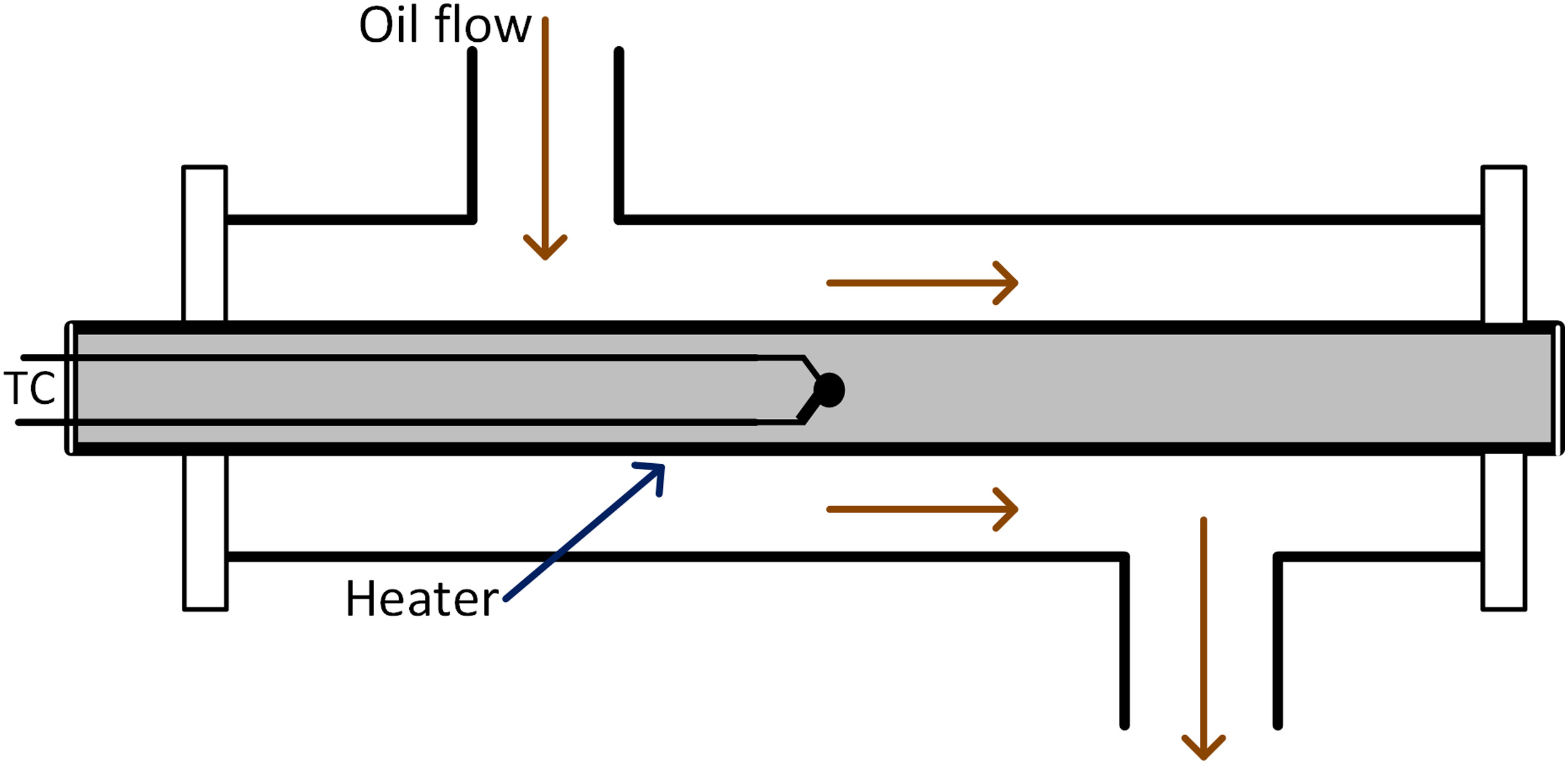
The apparatus has a reservoir with a capacity of approximately 900 mL, a pressure rating of up to 69 bar, and a maximum test section surface temperature of 550°C (Branson, 2016). The oil flow rate may be varied between 0.1 and 10 mL/min, and the oil may be recirculated several times through the test section (recirculation) or passed over the hot surface only once (one-shot or single pass). The test section consists of the oil flowing over an electrically heated tube with a constant surface temperature, shown in Figure 6.
Portable fouling research unit
The Portable Fouling Research Unit (PFRU) is similar to the HLPS but larger; it is typically used to study crude oil fouling (Srinivasan and Watkinson, 2003; Watkinson, 2003; Srinivasan, 2008). It operates at flow rates of around 4,830 mL/min; pressures between 10 and 13.4 bar under a nitrogen atmosphere; and a maximum design surface temperature at the test section of 630°C, although testing was done at lower temperatures (initial surface temperatures between 300°C and 380°C and bulk oil temperatures between 200°C and 285°C) (Srinivasan and Watkinson, 2003; Watkinson, 2003; Srinivasan, 2008). Its tank has a capacity of 7.5 L of oil, and the oil circles back into the tank after passing through the test section. The test section is similar to that of the HLPS, but under conditions of constant heat flux (rather than constant surface temperature).
Experiment
To broaden the scope and number of possible experiments to study the coking behavior of gas turbine lubrication oils, a new facility was designed and built at TAMU (Juárez, 2021). Based on the information summarized in the literature review in the previous section, the parameters that should be controlled, measured, and varied in the TAMU test rig and between experiments were determined. The test rig should allow the researcher to control the time the oil is exposed to high temperatures, the surface temperature to which the oil is exposed, and the oil’s flowrate, pressure, and level of exposure to oxygen. Similar to the experiments described in the literature, the deposits’ appearance, the induction time, and the deposit formation rate should be the parameters measured each experiment and used to analyze the degradation process. Finally, the rig should allow for the study of different kinds of lubricating oils with different basestocks, additives, and antioxidant type and quantity. The apparatus at TAMU uses a flowing oil method like that of the HLPS and PFRU as it better simulates oils in operation when compared to static oil and heated plate experiments. In addition, it expands the test conditions that are reached by other flowing-oil experiments in existence. It can reach higher temperatures (up to 650°C) and can vary the oil flow rates within a wider range (up to 14 mL/min). Finally, one notable advantage is the ability to change the test section geometry in the TAMU apparatus to meet different needs and simulate different scenarios of interest. The tests discussed in the previous section do not have this advantage.
The experimental apparatus consists of a flow loop, illustrated in Figure 7. During a test, new oil is inserted into Reservoir 1. The temperature of the oil in the reservoir is monitored during the test using the thermocouple in the thermowell. The test section is initially heated to a target temperature as measured by the thermocouple placed in between the two band heaters. The band heaters can reach temperatures up to 650°C. Once the target temperature is reached, the oil is pumped through the test section and then back into Reservoir 1, or into Reservoir 2. Returning the oil to Reservoir 1 allows it to be exposed to the high temperature multiple times, while directing it to the second reservoir exposes the oil to the high temperatures only once. Both reservoirs have a 1 L capacity. The bulk oil temperature and pressure are measured before and after the oil passes through the test section. The temperatures measured in the Reservoir 1 thermowell, at the oil inlet, and at the oil outlet are recorded every 16 seconds. The sampling frequency can be altered as needed depending on the expected test length. Finally, the test rig can be pressurized up to 69 bar if the effects of pressure on the degradation process are being studied. In addition, the system can be purged with an inert gas to study thermal decomposition only, or the presence of oxygen can be permitted in order to study oxidation. Although the surface temperature varies with axial position over a range, the temperature distribution in the test section is maintained constant over time with a temperature controller connected to the thermocouple in the test section, as shown in Figure 7. As time passes, the oil degrades and solid deposits form, build up, and attach to the high-temperature surface. These deposits hinder the heat transfer from the heated surface into the oil, causing the outlet oil temperature to decrease. Since the outlet oil temperature is measured during the test, the point at which the deposits start forming is captured. When this constant-temperature condition is used, the end of the induction time (the point at which deposits start forming) can be obtained by simply using the outlet oil temperature measurement. The information obtained with this method can be used to set upper operating temperature limits in an engine of interest. If so desired, the test can be modified so that the oil outlet temperature is maintained constant and the heaters’ power output is measured. Using this condition, the end of the induction time is marked by a increase in the power required to maintain the set oil outlet temperature due to the insulating effect of the deposits.
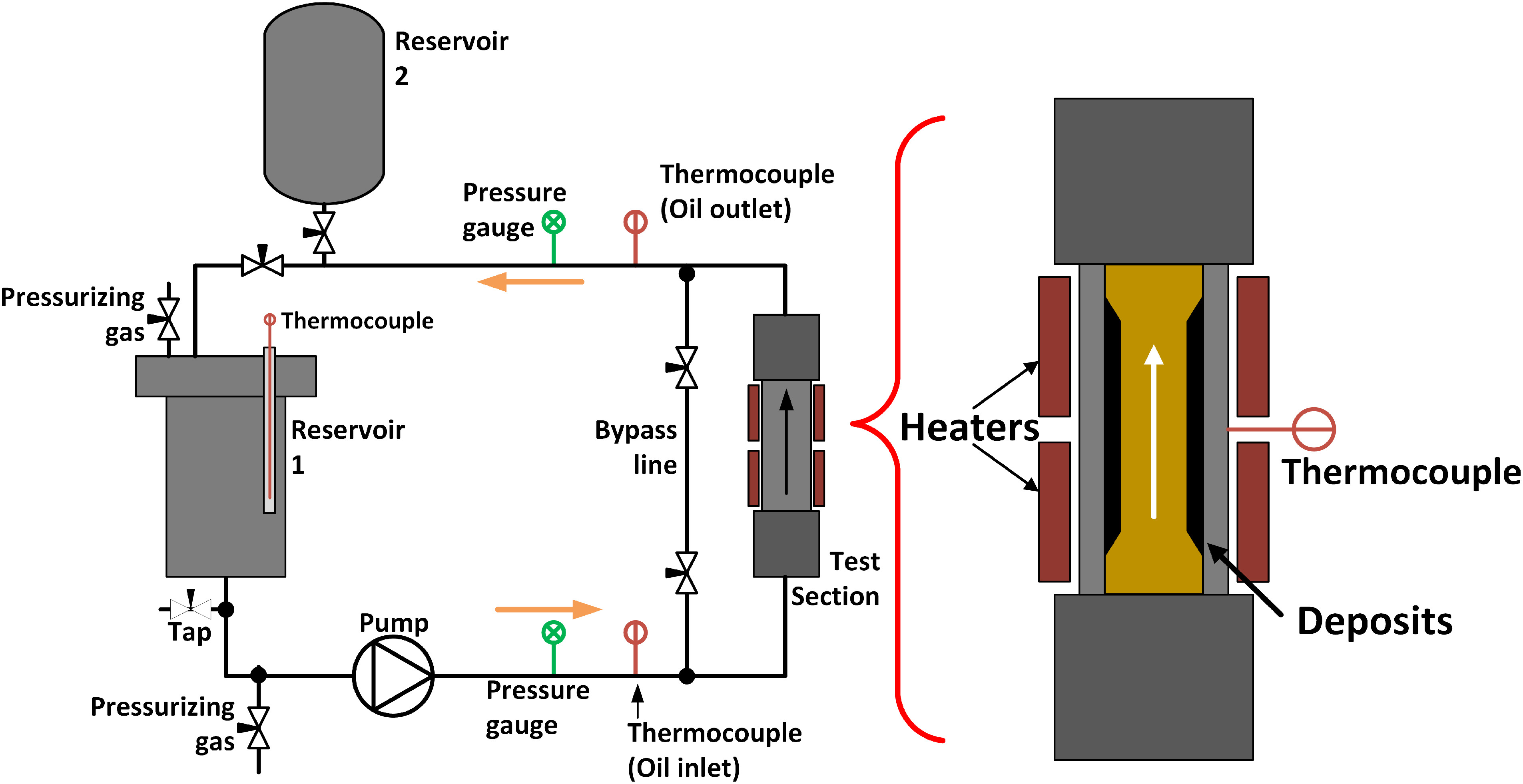
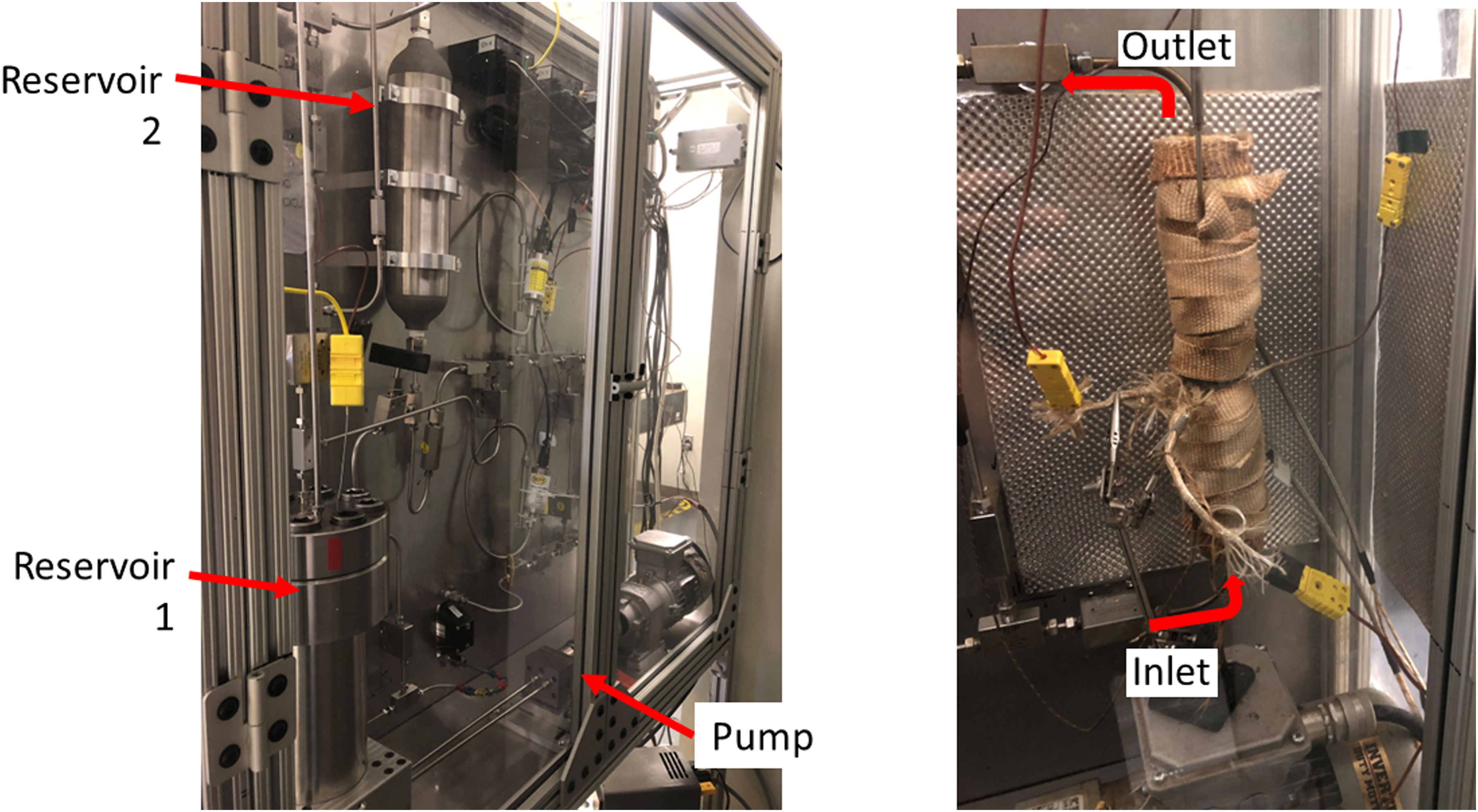
Figure 8 contains a picture of the assembled apparatus and points out some of its main components. The test section shown in Figure 8 has insulation wrapped around the tube and the heaters to reduce heat losses in this section. The rest of the system is not insulated which results in the oil’s temperature decreasing to almost room temperature before it passes through the test section a second time. Allowing the oil to cool simulates how the temperature of oils in operation decreases once it is no longer flowing through the high-temperature regions of the turbine. Two 300 W band heaters each with a length of 3.81 cm and inner diameter of 2.54 cm are installed around the 2.54-cm outer diameter test section tube and secured using clamping brackets. The thermocouple is attached between the heaters with its bead in contact with the outer tube surface using a high-temperature adhesive. It remains in contact with the surface and connected to the temperature controller throughout the entire test. Note that although Figure 8 shows several thermocouples in the test section, only one was required for the test. The remaining thermocouples were only used as additional temperature monitors. The pump has a variable frequency drive (VFD) that allows control of the oil flow rate through the system, up to 14 mL/min. A calibration test was completed to confirm that the oil flow rate can be accurately controlled using the VFD frequency. Because the temperature of the oil that exits the reservoir does not fluctuate during the test, the conditions at the pump (and the flow rate) remain constant. Further details on the new facility at TAMU is provided in the work by Juárez (2021).
After each test is completed, the oil is drained, and acetone is introduced and pumped through the system using the bypass line to remove any remnants of oil and deposits. The acetone is drained and replaced with new acetone a few times until it no longer shows signs of being mixed with oil when drained. Next, the oil to be studied in the next test is introduced to the system and pumped through the oil lines. The process is repeated twice. This repeated step ensures that both the damaged oil from the previous test and the acetone used to clean are no longer in the system when the next test begins.
Results and discussion
Figure 9 shows the oil inlet, oil outlet, and the Reservoir 1 temperatures measured during an oil degradation test by the oil inlet, oil outlet, and Reservoir 1 thermocouples pointed out in Figure 7. The temperature traces demonstrate how the outlet bulk oil temperature changes as deposits form on the heated surface. The test was run using 870 mL of a common synthetic turbine oil flowing at 10.4 mL/min. The oil was re-directed back into Reservoir 1 after passing through the test section. The temperature controller connected to the test section thermocouple (placed as illustrated in Figure 7) was set to 500°C. The flow in the test section is laminar and hydrodynamically fully developed but thermally developing. These conditions result in an axial temperature distribution along the 7.62-cm long heated portion of the test section. Based on previous testing, it is estimated that the inner test section surface temperature has a value of 306°C at the entrance of the heated portion. This inner surface temperature increases until it reaches 500°C between the two heaters (this is measured and maintained constant with the temperature controller). It then reaches a maximum value of about 517°C approximately 6.67 cm downstream of the start of the heated section, and then decreases as the heated portion ends.
Figure 9.
Temperature traces of a sample test obtained with the oil flowing at 10.4 mL/min and the test section temperature controller set to 500°C.
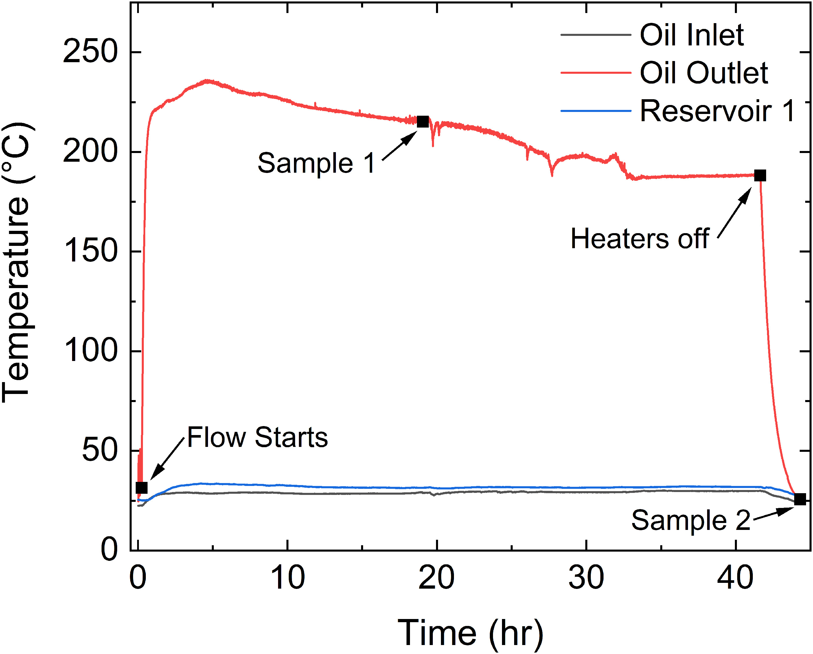
The oil started flowing when the pump was turned on at time t = 0.3 h, and Figure 9 shows how the measured outlet oil bulk temperature (measured by the outlet oil thermocouple in Figure 7) increased soon after. After reaching its maximum value, the oil outlet temperature started decreasing at t = 4.7 h, indicating that the deposits started accumulating. The outlet temperature dropped approximately 48°C until it finally stabilized at t = 33.3 h. The heaters were turned off at t = 41.6 h, ending the test after 8.3 h of measuring a constant outlet temperature. Note that although the oil reaches the temperatures measured by the oil outlet thermocouple (shown in Figure 9), it cools down to the Reservoir 1 and oil inlet temperatures also recorded in Figure 9 once it exits the heated test section.
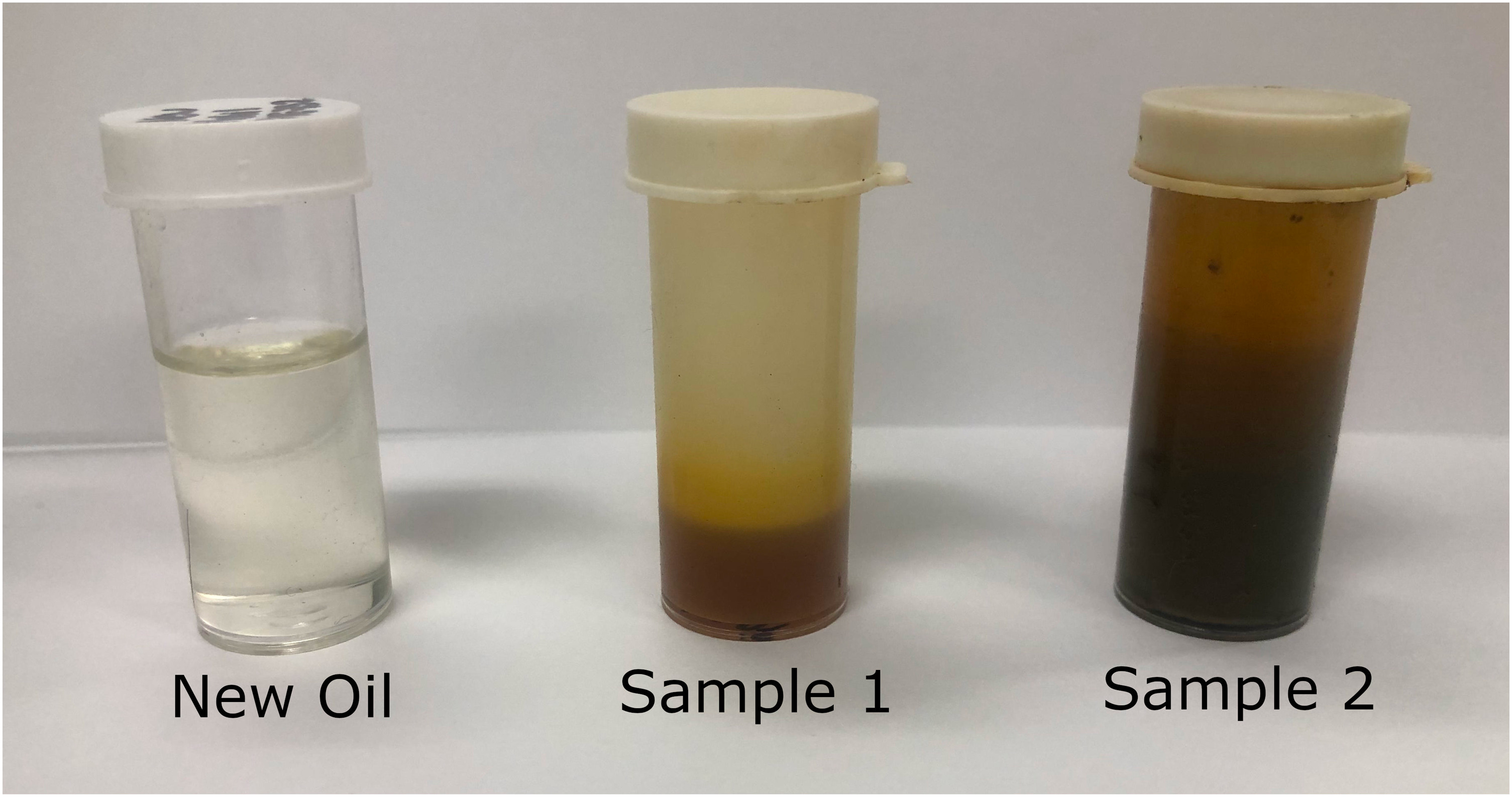
Two oil samples were taken during the test to assess how much the oil had degraded over the course of the experiment, based on its appearance. The samples were removed from a tap underneath Reservoir 1 and therefore were at temperatures like those shown in Figure 9 for Reservoir 1 and the oil inlet at the time of removal. To ensure the sample is representative of the state of the oil at the time of collection, the initial stream of oil is discarded before collecting the sample. Figure 10 contrasts the appearance of the oil at different times. The first sample was taken from the system at t = 19.1 h, as marked in Figure 9. It clearly shows that the oil had degraded and acquired a darker, golden color when compared to unused oil. The second sample was taken at the end of the test (t = 44.3 h), also marked in Figure 9. The oil in the second sample is a dark brown, indicating that the oil was severely damaged during the test. Figure 10 confirms that the oil composition and appearance changed over time as it was exposed to the extreme temperature conditions.
Figure 10.
Appearance of oil samples taken during the test compared to new oil. Sample 1 and Sample 2 were taken 19.1 and 44.3 h into the test, respectively. The oil was flowing at 10.4 mL/min through a test section with a central temperature set to 500°C.
Once the test ended, the test section was removed and inspected for deposits. The internal deposit build up is shown in Figure 1. The presence of these deposits corroborates that the decrease in outlet temperature seen in Figure 9 was likely due to the accumulation of coke.
Note that test section surface temperature rather than bulk oil temperature is used as the main test parameter. Both definitions of test temperature will probably yield similar trends when comparing the resistance to thermal breakdown of different oils in a range of temperatures. However, whenever thermal breakdown is discussed in the literature, hot spots on surfaces along the lubrication system are commonly blamed for rapid coke formation (Naidu et al., 1986; Kauffman et al., 2000a,b; Fitch and Gebarin, 2006; Novotny-Farkas et al., 2008; Exxon Mobil Corporation, 2016; ASTM International, 2020a). Naidu et al. (1986) also mention that engine manufacturers will typically design bulk condition lubricant temperatures to be within the temperature range that lubricants can withstand, especially if frequent oil changes are carried out. One explanation as to why lubricants fail anyway is the presence of hot spots where the temperature exceeds the lubricant’s thermal stability. Furthermore, even though the outlet bulk oil temperature is below that of the heated surface, some of the oil does come into contact with the extremely hot surfaces, and ignoring this fact may lead to skewed results that underestimate the conditions to which the oil is exposed.
Future work
Although further testing is required to prove the repeatability and well-controlled nature of the experimental parameters, the experiment and apparatus are promising. Future work will involve testing of various oils with different properties over a range of temperatures and studying the effect of temperature, oil composition, and residence time on induction time and deposit buildup. Depending on the information desired, the experiment can also be adapted to use the constant heat flux constraint instead of the constant surface temperature constraint by adding the power input to the heaters as an additional indicator of coking. In addition to determining the induction time, other methods such as Energy Dispersive Spectroscopy (EDS) and gas chromatography can be used to study the composition of the deposits that accumulate and of the oil samples that are removed during the test. Finally, if the effect that a single pass through the heated surface has on the oil is of interest, the oil can be routed into Reservoir 2 (instead of back into Reservoir 1) after passing through the test section. In this case, the oil in Reservoir 2 can be analyzed to examine how the oil composition changes in a single pass through as a function of the test section surface temperatures which can give interesting insight into the initial steps of the degradation process.
Summary
Coking of gas turbine lubrication oils is a concern in some turbomachinery applications where high-temperature conditions are present. Background information on the current knowledge of oil coking was presented in the first part of this paper. However, from the literature search herein, it is clear that fundamental information related to the prediction and understanding of the coking phenomenon and related parameters are somewhat lacking in the turbomachinery community. Additional laboratory experiments that match the temperatures, heat transfer mechanisms, and pressures for gas turbine applications is needed. To this end, a new test rig was developed and assembled at TAMU as part of an effort to better understand the lubricating oil degradation process at high temperatures that leads to the formation of solid deposits. The experiment and apparatus take advantage of the importance that surface temperature, bulk oil temperature, and residence time have on the oil degradation process and of the insulation effect that deposit formation on hot surfaces has on the heat transfer between the hot surfaces and the lubricating oil that is meant to cool the system. Results were presented for an off-the-shelf, common gas turbine lube oil. Coke deposits were shown to form at a set temperature of 500˚C after about 4.7 h at a flow rate of 10.4 mL/min. The test rig and experimental procedure demonstrated for the first time here for a gas turbine oil can be used for future experiments designed to characterize the coking limits of various lube oils over a wide range of conditions.