
Introduction
This paper presents the work on part-span rotating stall in a high-speed compressor. Part-span rotating stall usually occurs at part-speed as the stability limit of one or more blade rows is reached (Day et al., 1978). In this state the compressor is operating in stable rotating stall, whereby multiple stall cells are present local to the hub or, more commonly, the tip region, and can be confined to a limited number of blade rows. The remainder of the span operates normally.
The majority of published research on rotating stall is based upon low-speed compressor testing where the phenomena can be studied in a controlled manner. Such testing on high-speed machines is considerably more complex. Day and Freeman (1994) presented a systematic comparison between behaviour at low and high speeds, using a three-stage compressor at the Whittle Laboratory and a Rolls-Royce Viper engine, with an 8 stage 5:1 compressor. This comparison demonstrated similarities between both machines and confirmed that rotating stall always precedes surge even at high-speed conditions. It was also reported that low-speed operation of the engine resulted in multi-cell part-span stall local to the front stages (referred to as “front-end stall”). This was shown to arise due to the matching effects for multi-stage compressor, which cause the front to become stalled at part-speed working line conditions whilst the compressor as a whole remains stable. For this reason, the presence of rotating stall in the front stages did not impair the operation of the engine during starting. Although this type of rotating stall may not result in surge or massive loss of power, it can cause excessive vibration and noise. From an industrial perspective, it is important to understand the factors that influence changes in stall characteristics as it may result in moving from a safe operating regime to one that causes rotor blade failure. These effects are normally assessed by engine strain gauge tests, which are used to map out stall boundaries.
While the overall aerodynamic stability of the compressor may still be adequate, the part-span rotating stall (especially at front stages) is typically higher risk from an aeroelastic vibration point of view, as the phenomenon generally occurs at higher frequencies than full-span stall and has greater potential to interact with the resonant modes of the compressor blades (Baumgartner et al., 1995). When the frequency of rotating stall is close to the natural frequency of a blade vibration mode, the two frequencies can “lock-in” giving rise to high vibration levels, which may result in high cycle fatigue failures (Kielb et al., 2003). This type of event is generally categorised as a main subset of non-synchronous vibration (NSV), which can occur during compressor operation driven by aerodynamic flow unsteadiness such as rotating stall or vortex shedding.
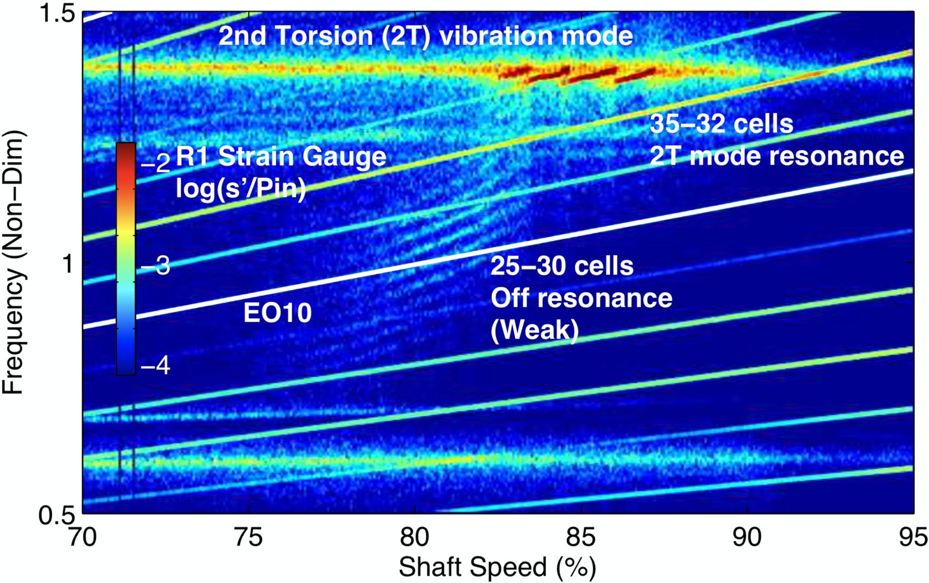
Figure 1 shows an experimentally measured lock-in event reported by Dodds (2016). Between 77–83% speed a multiple mode pattern of 25–30 lobes, driven by rotating stall near blade tip, can be identified in the strain gauge spectrum. Above 83% speed, the stall activity “jumps” to become dominant at a higher frequency, interacting with the second torsion vibration mode. In total 4 “streaks” can be observed to cross this mode, corresponding to a 35-cell pattern followed by 34, 33 and 32 cells. A key point here is that below 83% speed the stall phenomenon occupies a wide frequency range and is incoherent in the sense that multiple modes appear to coexist. At higher speeds, the stall phenomenon appears to become constrained to a fixed frequency in the rotating frame aligned exactly with the torsional mode. In this condition the fluid and structure becomes strongly coupled and the near-fixed frequency of the blade vibration mode drives the aerodynamics such that the stall cell count is forced to adjust naturally to maintain this coupling as the shaft speed changes.
This type of interaction has been reported in recent experimental and computational investigations such as Kielb et al. (2003), Dodds (2016) and Holzinger et al. (2016). As blades in multi-stage compressors become more loaded, the occurrence of such events is expected to be frequent. As turbomachinery blade aerofoils are thinned to improve performance and reduce weight, aeroelastic challenges become more crucial which highlights the importance of accurate prediction of transient flow behaviour in such conditions. Moreover, the use of titanium blade-integrated-disks, i.e. blisks, is becoming more common. Such structures have very low mechanical damping in contrast to traditional bladed-disk assemblies and will be more prone to high amplitude vibrations in such situations.
The objective of this paper is to computationally investigate the interaction between part-span rotating stall and vibration of a front stage rotor in a multi-stage high speed compressor. The paper demonstrates the capability of CFD in modelling part-span rotating stall events at off-design conditions and the coupling between stall and blade vibration through aeroelastic calculations. The occurrence of a spatial ”lock-in” event will be presented, where the presence of blade vibration modifies the circumferential cell count of part-span rotating stall in a manner similar to the experimental case shown in Figure 1.
Computation model and the flow solver
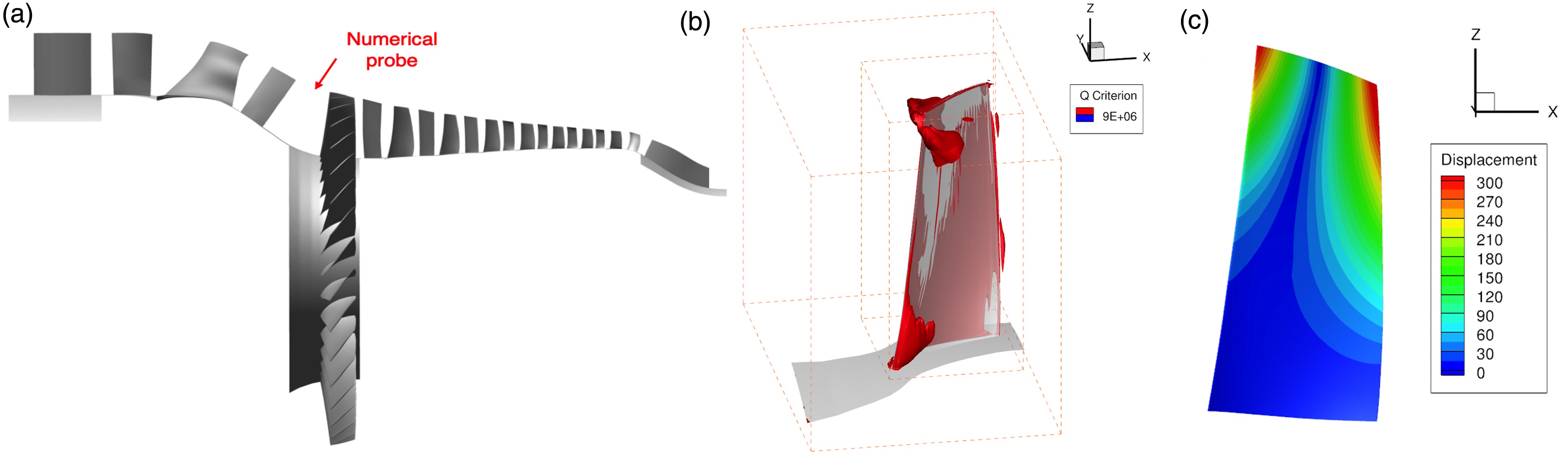
The research rig compressor was designed by Rolls-Royce and is representative of a modern high-speed machine. Experimental investigations have been carried out on the test rig to study stall and surge in a high-speed compressor and the results have been reported in Dodds and Vahdati (2015a). The compressor has eight stages with an inlet guide vane (IGV) upstream of the first rotor. The IGV and the first two stator rows (Stators 1 and 2) are of the variable stagger type (VSVs). Tip clearances and stator shroud clearances are representative of a modern high-speed compressor and the Rotor 1 (R1) relative inlet flow is supersonic at design conditions. A meridional schematic view of the compressor is shown in Figure 2. A choked nozzle was used at the domain outlet which allows atmospheric conditions to be used at both inlet and exit. Constant speed characteristics were obtained by adjusting the throat area of the nozzle. The stagger of the three VSVs (IGV, S1 and S2) were held at fixed positions throughout this investigation.
Figure 2.
(a) The unsteady computation domain; (b) Q criterion in the R1 domain calculated in the steady state computations and (c) Rotor 1 first torsion (1 T) mode shape.
The grids used for the blading are semi-structured, with hexahedral elements around the aerofoil in the boundary layer region, and prismatic elements in the passage. The end-wall boundary layers are resolved by refining the grid radially towards the hub and casing (Sayma et al., 2000). A typical passage mesh contains approximately 300,000 grid points, 44 mesh layers on the blade, 6 layers in the tip gap and approximately 800 points in the circumferential direction. The clearances between the rotor blades and the casing were set at a level consistent with the experimental test. Fillets at the blade ends and leakage flows through the shroud cavities beneath the stator vanes were not included since the stall cells investigated in this work are located at R1 blade tip. Steady analyses with these features included showed their relative importance to be limited compared to other effects such as VSV stagger angles. In the steady computations, the interface boundaries between stationary domains and rotating domains are modelled as mixing planes. In total, the single passage computation domain consisted of approximately 5 million nodes.
All the computations are performed using AU3D, which is a 3D, time-accurate, viscous, finite-volume compressible flow solver (Sayma et al., 2000). The unsteady flow cases are computed as URANS, with the basic assumption that the frequencies of interest are sufficiently far away from the frequencies of turbulent flow structures. In the current work, the source term of the standard Spalart-Allmaras is scaled, based on the local pressure gradient and the velocity helicity of the flow, to enhance the capability of CFD in conditions near to stall (Lee et al., 2018a). The parameters of the turbulence model are held constant in the present work. Furthermore, a generalised wall function (Lee et al., 2018a) valid for non-zero wall pressure gradient is also used to improve the accuracy of boundary conditions at the wall. The resulting CFD code has been used over the past 20 years for flows at off design conditions with a good degree of success (Vahdati et al., 2011; Choi et al., 2012; Lee et al., 2018b). Moreover, the methodology used in this work has been applied in part-span rotating stall modelling of multi-stage high speed compressor and showed a good degree of success compared with experimental measurements (Dodds and Vahdati, 2015b).
Investigation strategy and post-processing techniques
All computations were undertaken at 85% of compressor design speed, which showed significant interesting activity in the experiment when the compressor was aerodynamically mis-matched. Part-span rotating stall was observed in the front stages which persists indefinitely as a stable phenomenon, as the downstream stages operate sufficiently stable to prevent stall/surge of the whole compressor. It was also observed that the frequency of R1 tip rotating stall is in close proximity with that of a blade natural mode. Therefore, the main objective of this work is to investigate the development of part-span rotating stall in the tip region of R1 and its interaction with the vibration of R1 blades.
The investigation was carried out in 3 steps:
In the first step, steady state operating conditions of the compressor were obtained based on single passage model. The obtained single passage steady state solution was expanded to obtain a full-annulus geometry of R1 (Figure 2). Based on the expanded initial solution, unsteady computations were carried out using mixing planes between blade rows. The justification for the choice of model is based on the assumption that the part-span rotating stall is limited to the nearfield of R1; the effect of this assumption will be examined in this work by extending the modelled full annulus domain to IGV and S1.
Unsteady aerodynamic computations were performed without physical vibration of R1 blades. This allows investigation of the natural formation and development of stall cells. Effect of R1 operating point and tip clearance on rotating stall development are studied.
Unsteady aeroelastic computations were carried out by prescribing R1 blades with a fixed amplitude vibration in the mode of interest. Using this partially coupled approach, influence of blade vibration on the development of rotating stall can be studied. Frequency and nodal diameter (ND) of vibration are varied to study their impact on lock-in.
The steady state validation has been reported by Zhao et al. (2018) and Zhao et al. (2019) and hence are not presented here. In summary, flow separations are predicted to be local to R1 tip, S1/R2 hub and the tip of back-stage rotors. The findings show similar trend with the experimental measurements in Dodds and Vahdati (2015a). The steady state solution for R1 is shown in Figure 2b, displaying an isosurface of the Q criterion parameter for R1. Vortex like structures can be observed in the passage near blade tip, with flow “spilling forward” of the leading edge. Using a full annulus model of R1, it will be shown that flow structures arisen from these disturbances propagate relative to the rotors and can couple with tip-dominated blade vibration modes (e.g. the 1 T mode for R1 shown in Figure 2c).
In order to gain some physical understanding of the transient behaviour, for instance the onset and development of stall cells, the temporal and spatial evolution of flow field was interrogated by means of numerical probes. In this investigation, transient data was collected at 95% radial height upstream of R1. The collected data has a circumferential resolution of 1,440 probes and a temporal resolution of 300 samples per shaft revolution. For the results presented in this paper, all the numerical probes are locked in positions stationary with respect to R1, i.e. recording in rotor frame of reference. Consider a pattern of m stall cells propagating around the circumference at a speed
where n denotes the frequency of rotating stall with units in Engine Order (EO); 1EO is the frequency of shaft revolution.
A temporal discretisation level of approximately 200 time steps per rotor blade vibration cycle was used throughout this investigation, which was determined iteratively so that approximately the frequency of rotating stall was resolved by approximately 180 time steps. Convergence studies were undertaken and confirmed that the results were insensitive to further discretisation in time.
Unsteady without blade vibration
In the first step, unsteady computations were performed without blade vibration, so that the natural formation and development of stall cells can be investigated.
Figure 3a shows the evolution of solution at 95% radial height of R1 inlet, in terms of the circumferential profile and modal content of unsteady axial velocity. It should be noted that data presented here is in rotor frame of reference. In this figure, and figures of the same type that follow, the unsteady axial velocity (contour in the top plot) and its modal amplitude (contour in the bottom plot) are normalised by the circumferential mean axial velocity from the steady solution. Variation in axial velocity indicates the presence of flow distortion or unsteadiness. These signals can then be further identified based on the circumferential mode spectra. Circumferential disturbances such as potential and wakes appear on a single mode order equalling blade counts, whereas stall can manifest as signals spread across multiple mode orders for non-axisymmetric type, or as a single dominant mode for fully developed axisymmetric rotating stall.
Figure 3.
(a) Evolution of circumferential profile and modal content of axial velocity at R1 inlet, 95% span; (b) Contour of normalised unsteady axial velocity at inlet to R1, rev 14; (c) Circumferential spectra of unsteady axial velocity at 95% radial height, rev 14.

It can be seen from Figure 3a that travelling flow disturbances emerge after approximately 4 revolutions due to flow separation at R1 tip. The axial velocity disturbances have an amplitude close to 10% of the mean flow and are seen to travel circumferentially relative to R1 blades. The travelling path of these disturbances can be identified by tracing the peak (or trough) of axial velocity contour. For the case studied, disturbances are seen to travel with a circumferential speed of approximately 26% of the shaft speed, in the direction opposite to rotor rotation. In the absolute frame of reference, the observed results correspond to disturbances travelling at approximately 74% of the shaft speed in the same direction as R1.
The spatial structure of the rotating disturbances is revealed by the circumferential modal spectra shown in Figure 3a. Starting from revolution 4, a group of broadband-like signals appear in the vicinity of circumferential mode orders m = 20 to 28 (labeled as “RS” which denotes rotating stall). The fully developed flow solution at the inlet to R1 is shown in Figure 3b, where stall cells can be identified in the top 15% of the blade span with circumferential length scale slightly larger than one blade passage. Fourier decomposition of unsteady axial velocity at 95% blade span shows, as presented in Figure 3c, a band of signals centred around a dominant mode of m = 23. It was found that the dominant mode m = 23 corresponds to a frequency of approximately 6.05EO. The aliased signal between the rotating stall and R1 potential (labeled as “R1-RS”), around mode m = 11, is also shown in Figure 3c.
The development of rotating stall near the tip results in unsteady loading applied on the blades, which can potentially force or interact with blade vibration modes. For the case studied, the mode of interest is the first torsion (1 T) mode of R1 (mode shape shown in Figure 2c) due to the proximity of its natural frequency (5.7EO) to the dominant stall frequency (6.05EO). Time history of unsteady forcing on the Rotor 1 1 T mode was recorded in the computations and those results are examined next. It should be emphasised again that in this computation the blades remain fixed the modal forces represent how susceptible the mode could be to rotating stall in various NDs.
Figure 4 shows the time history and temporal spectra of modal force for R1 1 T mode. Modal force is calculated by integrating unsteady forces on blade surface and the mode shape of the 1 T mode (Vahdati and Imregun, 1996). In this figure positive nodal diameter denotes forward travelling modes and negative nodal diameter denotes backward travelling modes. Nodal diameters with the highest amplitude, namely −9ND to −13ND, are displayed in Figure 4. Due to the lack of coherent circumferential structure in the rotating stall, all the NDs are excited by unsteady forces, among which −11ND shows the highest amplitude. The forcing results are in agreement with the axial velocity measurements at R1 inlet (Figure 3), where 23-cell rotating stall aliases to −11ND unsteady loading on 34 rotor blades. Negative nodal diameter modes, i.e. backward travelling waves, are excited since the rotating stall spins slower than the rotor. Moreover, results shown in Figure 4 indicate that significant energy transfer can potentially occur due to the close proximity between the frequency of rotating stall and the natural frequency of the 1 T mode.
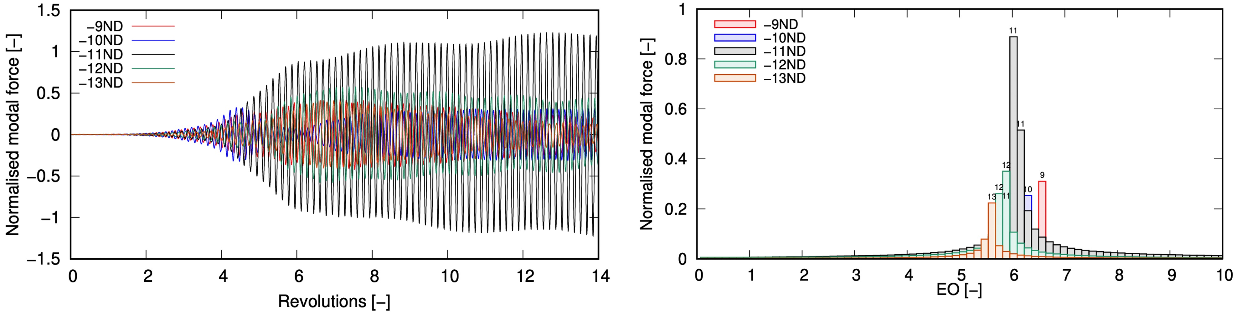
Table 1 summarises the dominant modal signals detected in the rotating stall in R1 tip region and the corresponding nodal diameters excited by these flow disturbances. In this table, the dominant frequency for each circumferential mode is displayed based on which the angular speed of stall cell is calculated. Results in the table show that the disturbances as a whole travel circumferentially at a speed approximately 74% of R1 shaft speed. However due to its non-axisymmetric structure, the spectra of perturbation spreads into several consecutive circumferential modes which excites multiple blade nodal diameters.
Table 1.
Dominant modes of R1 tip rotating stall.
| ND [−] | m [−] | ||
|---|---|---|---|
| −9 | 25 | 6.52EO | 0.74EO |
| −10 | 24 | 6.24EO | 0.74EO |
| −11 | 23 | 6.05EO | 0.74EO |
| −12 | 22 | 5.86EO | 0.73EO |
| −13 | 21 | 5.58EO | 0.73EO |
Effect of R1 operating point - open and close stator 2
To investigate the effect of mean flow on the rotating stall development, computations were performed at different R1 operating conditions. Due to the matching of compressor, throttling at the compressor exit does not lead to significant variation of R1 operating point. Therefore, in the current work R1 operating point was varied by opening and closing S2. Unsteady computations were performed where S2 stagger angle was varied by 1 degree increment.
Figure 5 shows R1 operating points obtained from steady state calculations. In this paper negative stagger angle change denotes opening and positive values denote closure. It can be seen that the nominal R1 operating point (0) is on the positive slope of the characteristic, which is not unusual for front stage rotors in multi-stage compressor operating at part-speed. Closing S2 (+) pushes R1 further into stall and opening S2 (−) reduces the loading on R1 and moves to the negative slope of the characteristic. Iso-surface of Q criterion for the −2 and +2 conditions are also shown in Figure 5, where opening S2 appears to reduce the intensity of spilling forward of leading edge flow.
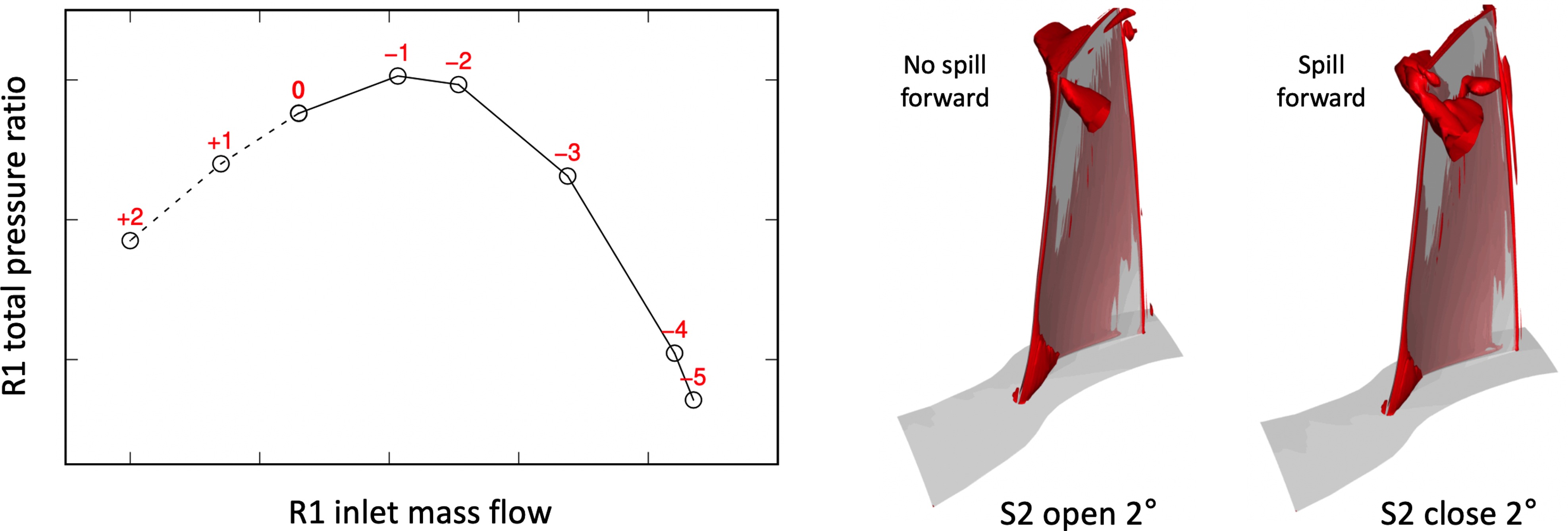
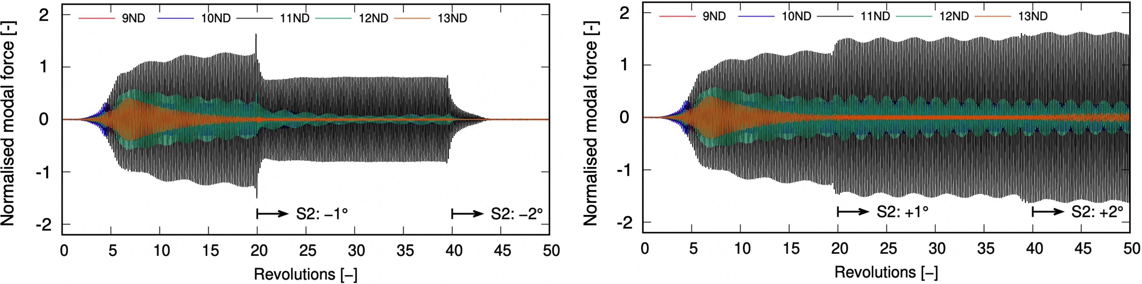
Figure 6 shows the time history of the 1T modal force when S2 is opened and closed transiently. Both sets of calculations were initiated from the same steady state solution at nominal S2 stagger setting (0). The setting was kept constant for 20 shaft revolutions to allow sufficient development of flow unsteadiness. At revolution 20, the stagger angle of S2 was changed by 1 degree. This process was repeated at revolution 40, where S2 was opened and closed by 2 degrees from the nominal setting. It is seen from Figure 6 that opening S2 leads to a reduction in modal force for all nodal diameters, which is driven by the reduction of flow unsteadiness as R1 becomes unloaded. Rotating stall is fully cleared when S2 opens by 2 degrees. Closing S2 results in an increased R1 forcing levels, especially in the dominant rotating stall mode −11ND. In both sets of simulations, −11ND remains the dominant mode, indicating the rotating stall remains largely in a 23-cell pattern. Interestingly, the disappearance of rotating stall (S2 stagger change from −1 to −2 degree) corresponds to the R1 characteristic changing from positive slope to negative slope (as shown in Figure 5).
Effect of R1 tip clearance
The tip clearance of R1 was varied in this work to study its impact on the tip rotating stall. The tip clearance studied ranges from 50% to 200% of the nominal value. The authors are aware of the deficiencies of URANS and S-A turbulence model in modelling tip leakage flows; the main focus here is the main “inviscid” interactions between the leakage jet and the development of these large length scale rotating stall cells.
Figure 7 shows the predicted modal force levels of R1 with four tip clearance sizes. It is seen from these plots that, as tip clearance size increases, the dominant modal force changes from −8ND (50%) to −11ND (100%) and −14ND (200%), which indicates that the dominant stall cell pattern changes from 26-cell (50%) to 20-cell (200%). This is likely driven by the fact that larger tip clearances contribute to larger sizes of stall cell, which consequently result in smaller number of cells circumferentially. It is also seen from these plots that as the number of stall cell decreases, the dominant rotating stall frequency also reduces. Calculations using Equations 1 and 2 show that the speed of stall cells remain constant at around 75% rotor speed for all the cases studied.

Unsteady with prescribed blade vibration
In the next step, unsteady computations were carried out by prescribing R1 with a fixed amplitude vibration in the 1 T mode. In this sense, the overall system is partially coupled (i.e. vibration influences the flow field and not the other way around), based on which influence of blade vibration on the unsteady flow field and development of rotating stall can be studied. For the work presented here, R1 blades are excited in the 1 T/−10ND mode with a fixed amplitude vibration. The vibration nodal diameter (−10ND) and frequency (5.7 EO) were intentionally chosen to be different from the dominant mode of the rotating stall (23-cell which forces −11ND in 6.05 EO), so that the impact of vibration on stall cell development can be assessed. The amplitude of blade vibration is kept constant at a level at which the maximum peak-to-peak displacement at blade tip leading edge is approximately 0.33% of R1 tip chord.
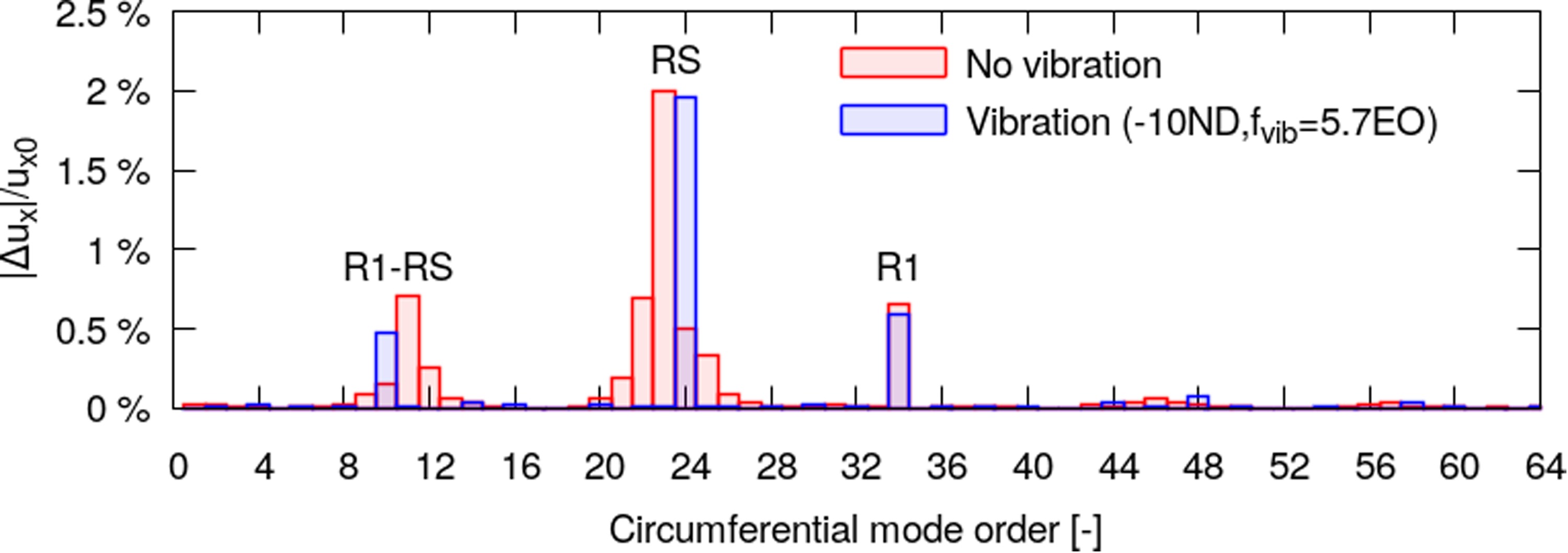
Figure 8 shows the axial velocity modal content at 95% radial height, obtained from fully developed solutions with and without R1 vibration. It is seen from the modal force plot that, unlike results obtained without blade vibration, a single mode m = 24 is observed during the development of rotating stall. The results indicate that, instead of a non-axisymmetric 23-cell dominant mode pattern, the rotating stall locks in (spatially) with blade vibration which results in a coherent 24-cell structure. The influence of vibration on rotating stall is clearly demonstrated in these figures, where a small amplitude motion (max pk-pk displacement about 0.33% tip chord) can vary the circumferential structure of rotating stall. It is also found that the resulting rotating stall has a frequency of 6.2 EO which is different from that of the vibration (5.7 EO), i.e. the circumferential order of rotating stall adjusted to couple with vibration but not the frequency. This indicates a strong non-linear interaction between stall and vibration where energy is exchanged between different frequency bands.
In the next step, the vibration nodal diameter was varied to study their impact on rotating stall. Simulations were carried out in the same fashion as before, where R1 vibration is prescribed in a fixed ND and the transient of flow unsteadiness was tracked. Figure 9 shows the dominant modes of unsteady axial velocity in the fully developed solution after approximately 40 revolutions of simulation. In this set of computations, the vibration frequency remains constant at 5.7 EO. It is seen that as the vibration ND changes from −11 to −8, the rotating stall modifies its cell count from 23 to 26 to stay lock-in with blade vibration. This coherent relationship is lost when the vibration mode goes beyond −8ND. As the number of stall cells change from 23 to 26, the frequency of rotating stall changes from 6.05EO to 6.85EO. Further increase in stall cell count (i.e. beyond −8ND) results in dominant rotating stall frequency higher than 6.85EO, which is 1.15EO higher than the vibration frequency. As the frequency difference increases, the energy exchange between the structure and the fluid becomes less efficient and hence the lock-in equilibrium is eventually lost. This phenomenon was observed in the experiment (Figure 1), where the cell count changes with compressor speed to maintain coupling. At lower speed the conditions for the energy exchange do not exist due to frequency differences. It should be noted that anomaly in trend is observed in Figure 9 at −14ND, where the dominant mode of unsteadiness is 24. The exact cause for this anomaly is unclear; it is postulated that the dominant mode (i.e. mode with highest amplitude) can be affected even without lock-in since the rotating stall has a non-coherent pattern. Further investigation is required to determine the cause of this phenomenon.
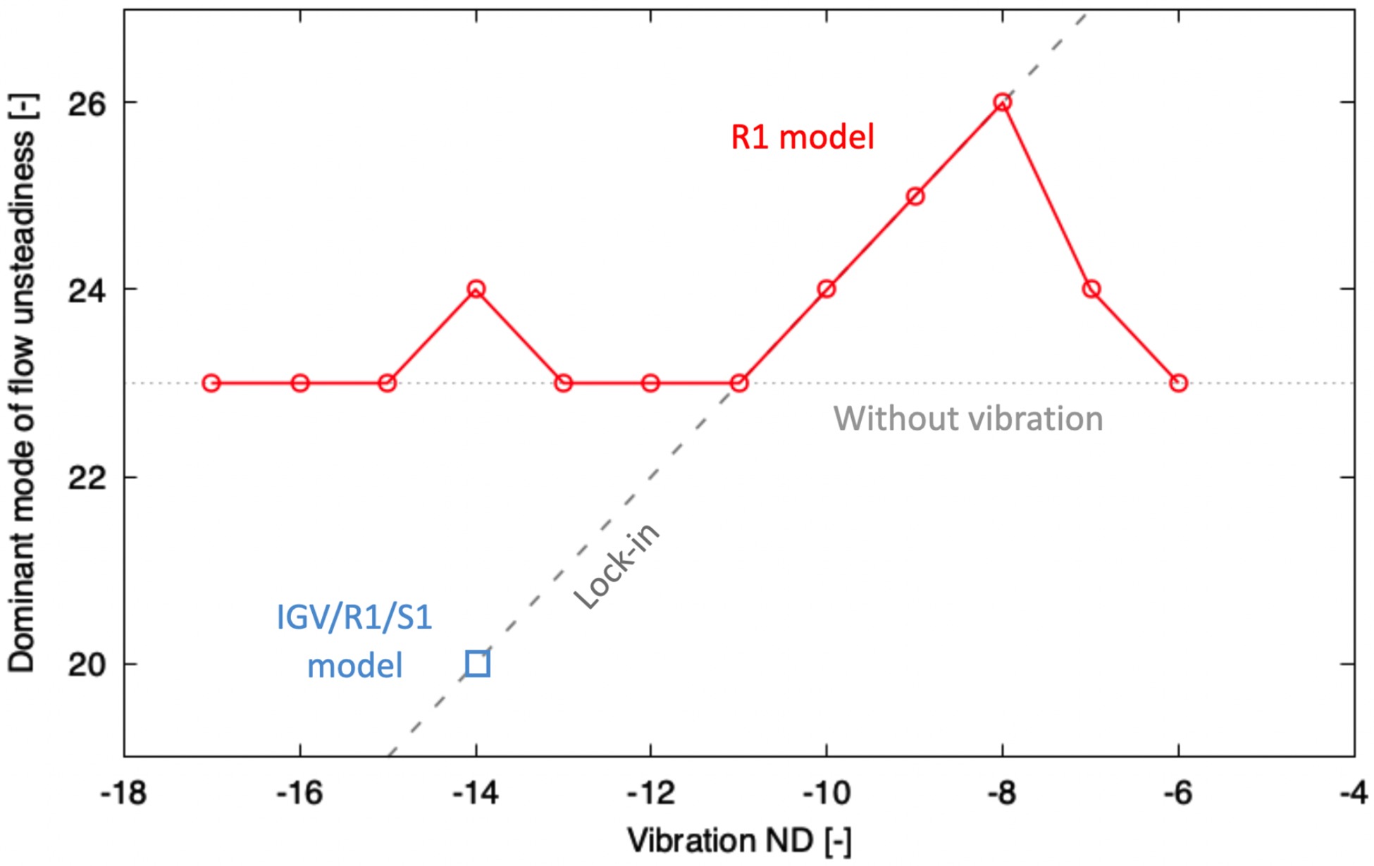
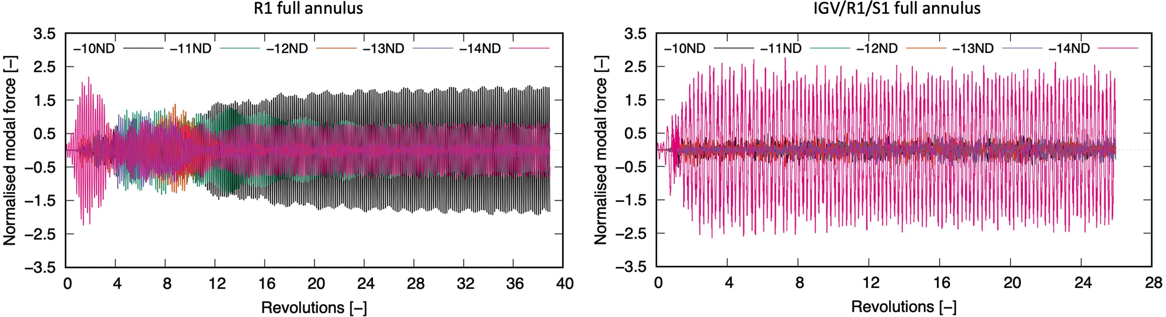
It is also observed from Figure 9 that no lock-in was achieved when the vibration ND decreases from −11ND, i.e. between −12ND and −17ND. In those simulations the fully developed flow field comprises less coherent structures with dominant mode no less than 23 cells. To investigate if this is driven by numerical boundary conditions, a new set of computation was conducted where the IGV and S1 were also expanded to full annulus besides R1. Sliding planes were used at the interfaces between IGV/R1 and R1/S1, which allowed circumferential unsteadiness to pass through without numerical averaging. Comparing results between the full-annulus R1 model and the full-annulus IGV/R1/S1 model, discrepancies emerge when the vibration ND decreases further from −11ND. To illustrate this, the resulting R1 modal force due to prescribed −14ND vibration is shown in Figure 10. It can be seen that the full-annulus R1 model shows spikes in −14ND force at around revolution 2, indicating an initial attempt for lock-in in a 20-cell pattern. However, the trend changes abruptly as more NDs experience forcing, indicating the circumferential pattern of rotating stall is changing and not coherent in a single mode. The fully developed solution after approximately 40 revolutions shows multiple NDs responding with significant forcing among which −10ND has the highest amplitude. The full-annulus IGV/R1/S1 model shows an initial increase in −14ND modal force during revolutions 0 to 2, similar to that of the full-annulus R1 model. However, a single dominant mode −14ND (20 cells) is seen in the full-annulus IGV/R1/S1 model throughout the simulation (26 revolutions). The fluid unsteadiness is spatially coupled with blade vibration as illustrated in Figure 9. The discrepancy between predictions by the two models is believed to be a result of mixing plane and sliding plane boundary conditions, where the presence of a mixing plane interferes and restricts the expansion of stall cells, thus limiting the cell count to 23 as shown in Figure 9. The lowest number of cells that can be modelled by a mixing plane approach is affected by the numerical boundary conditions as well as the mean flow (20-cell dominant mode was modelled by changing rotor tip clearance as shown in Figure 7). This restriction is alleviated when sliding plane is adopted, which allows more freedom for axial unsteadiness development. Therefore, it is in the authors’ opinion that the type and location of numerical boundary conditions need to be carefully chosen or examined in future studies of rotating stall so as to minimise modelling errors.
Conclusions
In this paper the part-span rotating stall and blade vibration of a multi-stage high speed compressor was investigated numerically at off-design conditions. Steady state computations showed that flow separation and recirculation formed local to the tip of Rotor 1. Using a full annulus model of R1 in unsteady calculations, these disturbances coalesce into flow structures rotating around the annulus at approximately 76% of the shaft rotational speed. Natural evolution of the rotating stall did not result in a coherent spatial pattern. The dominant mode of response was shown to be m = 23 which travels at frequency 6.05EO. Sensitivity studies showed that for the case studied, rotating stall was cleared when the rotor operating point moves from positive slope to negative slope on the characteristic. Moreover, larger tip clearance was found to lead to larger separation sizes and consequently a smaller number of cells in total.
Subsequent analyses were carried out with a prescribed R1 vibration in the 1T/−10ND mode at its natural frequency 5.7EO. Despite a small vibration amplitude (max pk-pk displacement of 0.33% R1 tip chord), a spatial “lock-in” event was observed where the circumferential order of the part-span rotating stall shifted to match that induced by the vibration mode, i.e. from m = 23–24. Moreover, in contrast to its natural form without vibration, the fully developed rotating stall showed a coherent axisymmetric stall signal m = 24 travelling at frequency 6.20EO. By varying the nodal diameter of the prescribed blade vibration, influence of vibration on rotating stall was further studied. Spatial lock-in was observed when the vibration pattern was between −11ND and −8ND. Lock-in in cell count lower than 23 cells were not successfully achieved with the full-annulus R1 model, which was believed to be influenced by the mixing plane boundary conditions. Subsequent full-annulus IGV/R1/S1 simulation with −14ND vibration resulted in coherent 20-cell rotating stall structure, which highlighted the importance of numerical boundary conditions in rotating stall modelling.
The effect of blade vibration on the development of part-span rotating stall is clearly demonstrated in this paper. Accurate prediction of unsteadiness and blade loading requires modelling of blade vibration especially when the rotating stall frequency is in the vicinity of natural vibration modes. It is also shown that the numerical model can offer more detailed knowledge of the transient flow field where comprehensive experimental measurements are challenging.