Introduction
Turbine rim seal purge flow and its interaction with the main annulus flow has been the subject of numerous studies in the past decade due their potential to provoke significant efficiency penalties in gas turbines. The main driver of these losses are the mixing losses of the relatively cold and low momentum fluid with the hot gas. Mixing losses are driven by the difference in momentum and flow direction. However by counteracting the momentum deficit, higher levels of hot gas ingestion can be induced due to the pressure deficit.
In literature substantial amount of research can be found that addresses the impact of rim seal purge flow on the main annulus flow aerodynamics. 05 reported on the entrainment of low momentum cavity fluid into the rotor hub passage vortex based on an experimental study performed in a two-stage low pressure turbine. Similar findings have been published by 17 for the stator hub passage vortex and 06 for the rotor hub passage vortex of a low pressure turbine, respectively. Furthermore, 09 have linked the pronounced lift off of the rotor hub passage vortex to the lower temperature of the purge flow with respect to the main annulus flow. 14 elaborated two sources of loss mechanisms; losses due to mixing of the purge flow with the main annulus flow as well as losses induced by the increased strength of the secondary flow structures through the rotor. The authors emphasized that the losses of both sources are found to be equal and indicated an efficiency penalty for low speed machines to be 0.56% per 1% of injected purge mass flow. The increased strength of the rotor hub passage vortex and the increased penetration depth of flow with negative incidence has been reported by 08. 18 reported on a decrease of efficiency by 0.6% per percent of injected purge mass flow based on measurements in a 1.5-stage high-pressure turbine. 20 performed a combined study on hub and shroud leakage loss mechanisms, highlighting that by 1.5% of purge flow injection at the hub, turbine losses are increased by 12%. The authors identified the purge flow mass fraction to be the parameter with highest leverage on purge flow losses. Additionally, the magnitude of the purge flow swirl velocity shows the potential of reducing the purge flow losses by 40–70%. 03 performed extensive studies on the rim seal purge flow effects in a single stage high-pressure turbine rig, providing both time-resolved experimental data and unsteady computational results at the rim seal exit and inside the hub cavity. The authors stated good agreement between experiments and predictions in terms of temperature and pressure on the rotating side of the cavity. After having validated the computational methods by the experiments, the authors found that the injection of purge flow causes additional blockage aft of the high-pressure vane which induces a detrimental effect on the power extraction of the rotor by means of increased incidence and reduced tangential velocity at rotor inlet.
Furthermore, extensive research has been performed on geometrical variations of the cavity exit regions for both shroud and hub cavity geometries. 15 showed the potential for significant efficiency gains by well-designed shroud cavity geometries. Moreover, 11 and 02 underlined the importance of the exit shroud cavity geometry on the interaction of shroud leakage flows and the main annulus flow. 12 reported on the leakage slot vortex present at the exit of the hub cavity to be the key flow structure which affects the leakage-main annulus flow interaction. Furthermore, the authors presented a systematic variation of the overlap-type rim seal design, highlighting that there might not be an optimum rim seal solution which leads to an improvement in terms of aerodynamic losses and sealing effectiveness for the full rim seal purge mass flow range. 19 have shown for different rim seal designs in a low-pressure turbine an attenuation of the passage vortex when increasing the distance between seal and blade leading edge.
The work presented in this paper aims to provide a new approach of reducing the detrimental effect of rim seal purge flow injection on the one stage performance of a high-pressure turbine by a geometrical modification of the rim seal exit. The improvements are shown with respect to a baseline rim seal geometry.
Experimental method
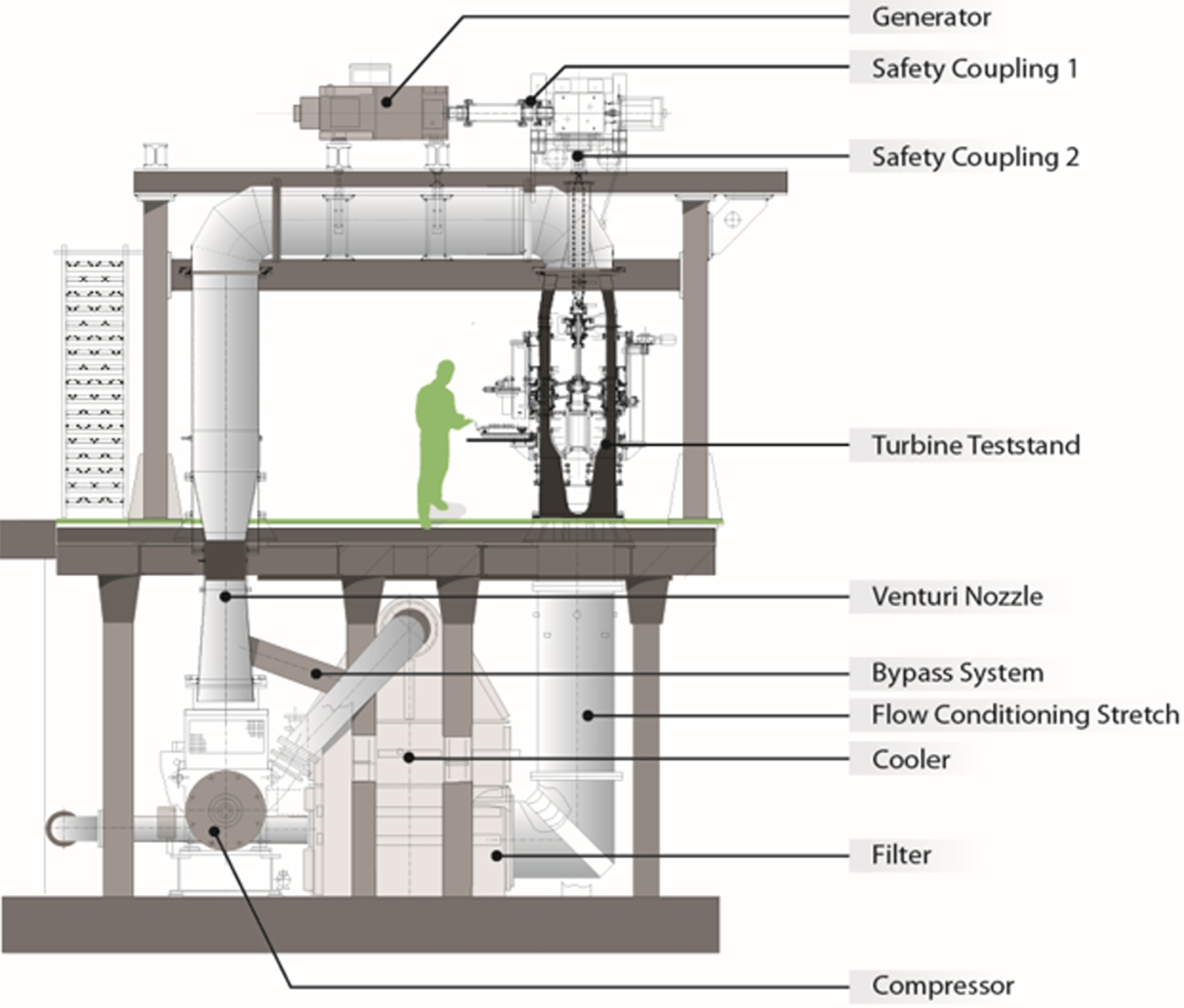
The experimental data presented in this work were gained from measurements in the research axial turbine facility “LISA” in the Laboratory for Energy Conversion (LEC) at ETH Zurich. A schematic view on the facility is presented in Figure 1. The test rig was assembled with a one-and-a-half stage, high-pressure turbine representative configuration including an unshrouded rotor and non-axisymmetric end wall contouring at hub for all three blade rows. The first stator was additionally equipped with contoured end walls at the tip. For the same blading two different rim seal exit geometries have been studied where one is termed as baseline and the other one consisting of geometrical features are indicated as PCFs.
Research turbine facility
The test facility is designed in order to accommodate moderate speed and a low-temperature model of an axial turbine with non-dimensional operating parameters that are matching real engine conditions. The air loop of the test rig is quasi-closed and includes a single stage centrifugal compressor, a two stage water-to-air heat exchanger controlling the turbine inlet temperature and a calibrated venturi nozzle for accurate mass flow measurements. At the exit of the turbine test section the air loop opens to atmosphere.
Upstream of the turbine test section is a 3 m long flow conditioning duct in order to ensure a homogenous flow field at the turbine inlet. Furthermore, the flow undergoes an acceleration ahead of the turbine to reduce the significance of any remaining flow non-uniformities from upstream. A DC generator absorbs the power of the turbine and controls the rotational speed with an indicated accuracy of ±0.02% (±0.5 rpm). The total inlet temperature T0,in is controlled by the water-to-air heat exchanger to an accuracy of ±0.3 K. In order to measure the torque on the rotor shaft, a torque meter is installed on the vertical shaft. Due to the limited pressure ratio πc,max = 1.5 of the centrifugal compressor, a tandem de-swirl vane arrangement is installed in order to recover the static pressure back to ambient level at the exit of the second stator (S2) which allows to reach the intended pressure ratio of π1.5 = 1.65.
The unshrouded rotor has a tip gap of 1% of the blade span and the tip gap variations between different assemblies is less than 1% of the tip gap which provides good repeatability. At the exit of the first stator (S1) the main flow is compressible with an average exit Mach number of 0.53. The current turbine configuration is derived from the turbine design extensively presented by 01. The increased blade row spacing between the first stator and rotor as well as an increased axial clearance at the exit of the hub cavity build the major differences.
Operating conditions
In order to account for changes in the atmospheric pressure for different measurement days, the turbine’s 1.5-stage total-to-static pressure ratio is kept constant at π_1.5 = 1.65 during the experiments. The pressure information given in this work are non-dimensionalized by the respective turbine inlet total pressure. Table 1 provides the key operating parameters as well as the geometrical specifications.
Table 1.
Operating conditions and geometrical details.
Purge flow injection and rim seal designs
During the measurements, the rim seal purge flow is continuously injected from the rotor upstream hub cavity along the full annulus. The mass flow is an off-take from the primary air loop upstream of the flow conditioning stretch and is measured by a standard nozzle. The bypass air is fed through ten nozzle guide vanes (Figure 2) around the circumference into the cavity underneath the first stator (S1) hub platform. A schematic of the rim seal purge flow path is presented in Figure 2.
Figure 2.
Schematic of rim seal purge flow path (left) and close-up view of rotor upstream rim seal (right).
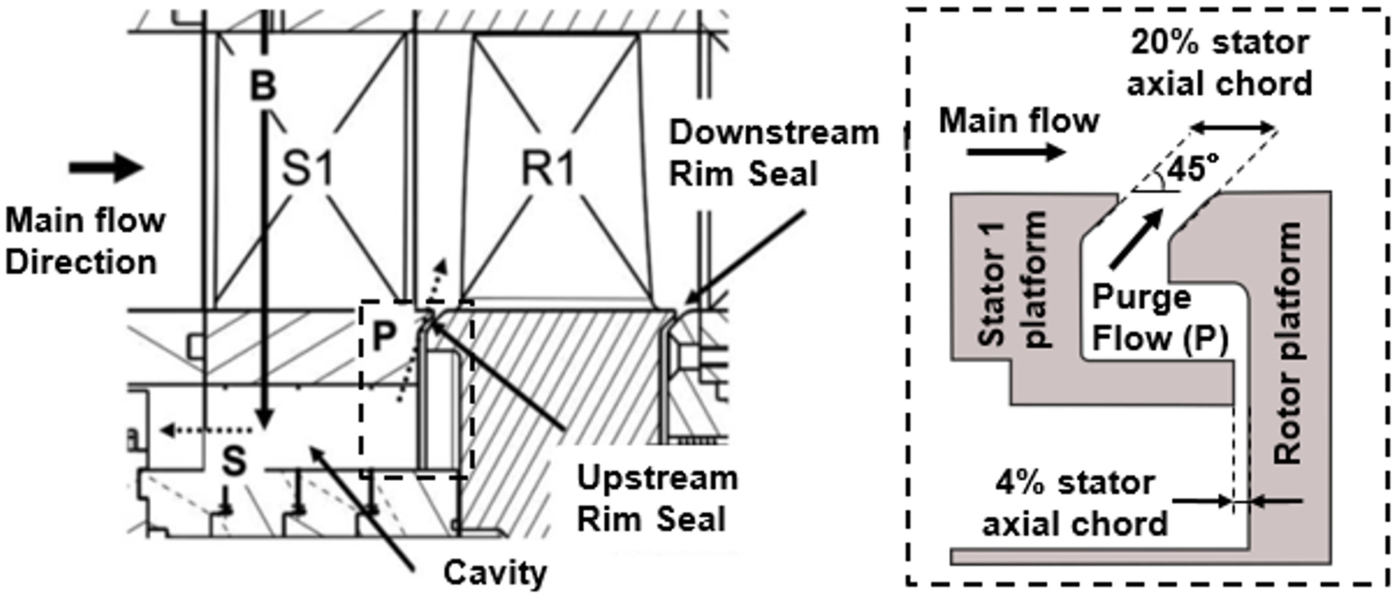
Once the bypassed air B has entered the hub cavity, the mass flow is separated by two different paths which are indicated by dotted arrows in Figure 2. The flow path labeled with P describes the injection of purge flow into the main annulus flow. The label S indicates the secondary flow path and the corresponding mass flow is ejected through the drum into atmosphere, after being measured by an additional standard nozzle. The pressure difference across the rotor downstream seal is controlled to be zero during the experiments, therefore the mass flow through the downstream rim seal gap is assumed to be zero.
Hence, the rim seal purge flow injection levels are defined by means of the injection rate (IR), given in the following equation:
In the present study, experiments for three different injection rates have been performed: IR0 = 0.0%, IR1 = 0.8% and IR2 = 1.2% which are representative to real engine conditions. Measurements for the IR0 = 0.0% test case have only been conducted at the rotor inlet. The IR1 = 0.8% case is termed as the nominal injection rate case whereas IR2 = 1.2% is considered to be the high purge mass flow case. The measurement accuracy of the injected amount of rim seal purge flow with respect to the turbine main mass flow is evaluated to be ±0.01%.
The characteristic geometrical details (Figure 2, right) of the rotor upstream seal are the rim seal interface gap width of 20% of the first stator axial chord as well as a sealing gap of 4% of the first stator axial chord. A platform chamfer angle of 45° is denoted. The main part of this work focuses on the impact of the novel geometrical features termed with PCFs which are installed on the stationary and rotating side (Figure 3). The primary design intention is to reduce the mixing losses which are associated to the injection of lower momentum rim seal purge flow. Specifically, the design intentions are formulated as follows:
Figure 3.
Rim seal designs stator 1 side (left) and rotor side (right) for baseline and PCF geometry. Indication of measurement planes “R in” and “R ex.”
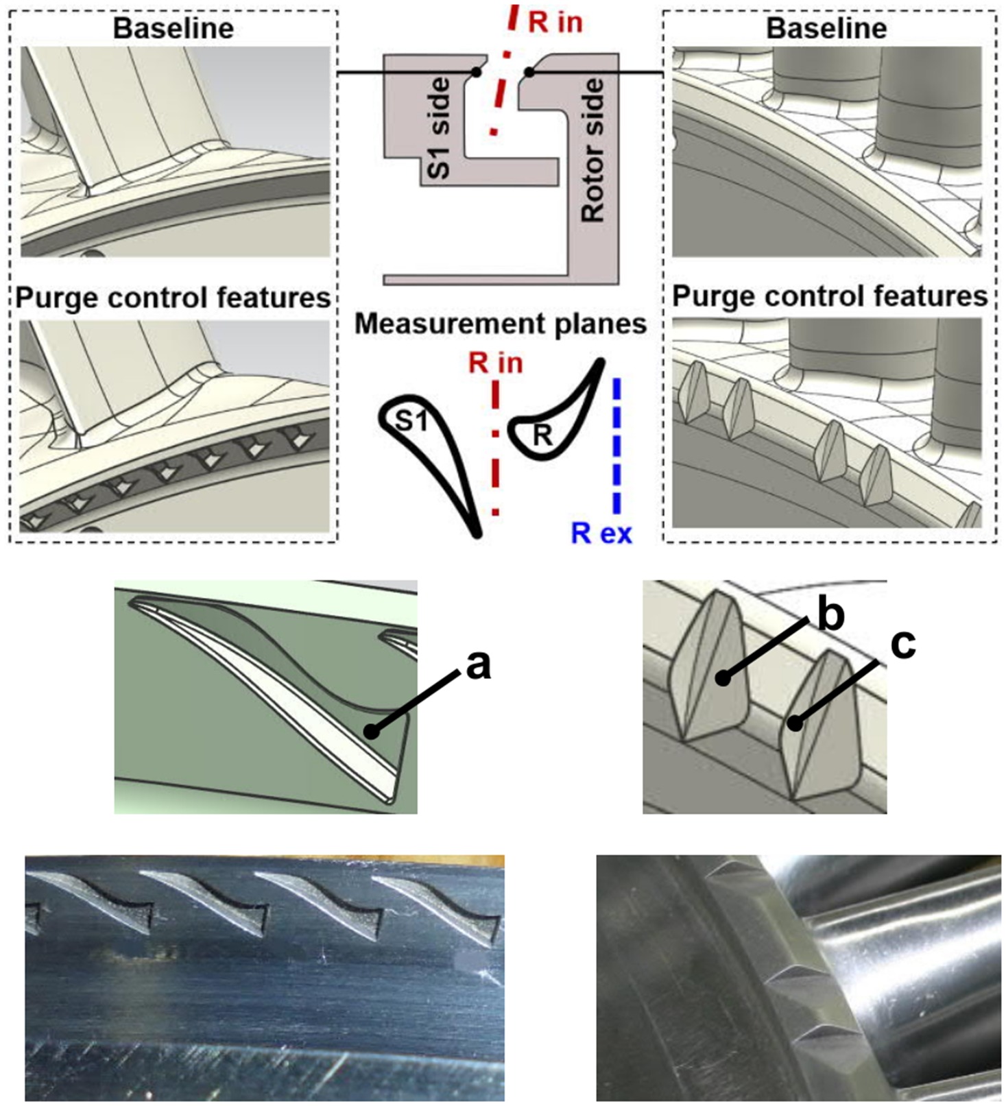
(1) Stator-sided purge control features: the primary issue on the stator side is the hot gas ingestion due to the circumferential pressure distribution caused by the first stator wake. The features target the guidance and alignment of the purge flow with the main annulus flow exiting the first stator and regulating the static pressure at the rim seal exit. The feature is designed as such that the depth of groove (a) is reduced towards the main annulus flow which induces an acceleration of the purge flow.
(2) Rotor-sided purge control features: the intention is to increase the momentum of the rim seal fluid, thereby altering the circumferential and radial velocity components. The groove (b) imparts an increased circumferential velocity, thereby adjusting the low momentum fluid to match closer to the main annulus flow. The angled surface (c) supports with imparting a radial component to the purge flow which targets to reduce high amount of hot gas ingestion.
Measurement technology
The time-averaged flow field at the rotor exit has been measured with a miniature cobra-head five-hole probe (5HP) with a probe tip diameter as small as 0.9 mm.
In order to measure the unsteady flow field at rotor inlet and exit, the FRAP is used. The probe technology has been developed in-house at LEC at ETH Zurich. Detailed information concerning the measurement technology can be found in 07 and 10. The FRAP allows to measure total and static pressure as well as flow yaw and pitch angle in a frequency bandwidth up to 48 kHz. Based on pressure and flow angle information, the flow velocity components and further flow quantities are derived. For temperature measurements the frequency bandwidth is limited to 10 Hz. The impact of the measured temperature on the pressure and therefore velocity component is judged to be very modest. In order to reduce the probe blockage effect, the FRAP has a 1.8 mm tip diameter and encapsulates two miniature silicon piezo-resistive pressure transducers. The 2-sensor FRAP is operated in a virtual 4-sensor mode in order to measure the 3-dimensional, time-resolved flow properties. The data is acquired at a sampling rate of 200 kHz over a measurement time of 2 s. The post-processing of the data is performed for three consecutive rotor pitches which results with the given sampling rate in a flow field temporal resolution of about 82 samples per rotor blade passing event, considering 54 rotor blades and a nominal rotational speed of the rotor of 2700 rpm.
The absolute measurement uncertainties achieved with the FRAP and 5HP at rotor exit are given in the subsequent Table 2 for a probe calibration range of ±24° in the yaw angle and ±20° in the pitch angle. Furthermore, the relative uncertainties of the total (pt) and static pressure (ps) are specified as a percentage of dynamic head.
Table 2.
Uncertainty bandwidth FRAP and 5HP.
| Yaw angle | Pitch angle | pt | ps | |
|---|---|---|---|---|
| FRAP | 0.62° | 0.64° | 2.8% | 3.7% |
| 5HP | 0.34° | 0.40° | 1.9% | 2.2% |
The experimental data presented in this work were acquired at two different axial locations by traversing the probes in radial and circumferential direction. The first measurement plane termed as “R in” is located upstream of the rotor and allows to measure the main annulus flow field as well as the hub cavity flow field by immersing the probe down to the sealing arm at −19% blade span (Figure 3). The second traverse plane, termed with “R ex” is located downstream of the rotor at a distance between the plane and the rotor trailing edge of 13% of the rotor axial chord.
Results and discussion
The current section provides the experimental results for the two rim seal exit geometries by keeping the same blading and end walls of the blade rows. Time-averaged as well as time-resolved measurement data are presented.
Aerodynamic performance analysis
In this section the sensitivity of the total-to-total stage efficiency with respect to two different injection rates and two rim seal exit geometries are presented. The definition of the aerodynamic efficiency which is used in this study, accounting for the rim seal purge flow injection, is given in the following equation:
In the post-processing is evaluated at each point of the measurement grid. The total pressure at rotor exit Pt,Rex is measured by the 5HP whereas the rest of the quantities are acquired with different instrumentation installed in the rig. Considering the measurement uncertainty of the probe, the operating point and the calibration model uncertainty, the calculated absolute standard uncertainty of the total-to-total stage efficiency is ±0.18%. The calculated relative standard uncertainty (efficiency difference Δηtt) is ±0.16%. Repeatability measurements have shown variations below 0.10%.
In Figure 4, the circumferentially and mass-averaged total-to-total stage efficiency difference (Δηtt) profiles for two rim seal purge flow injection rates are presented. The efficiency difference is based on the total-to-total stage efficiency values of the PCF case with respect to the baseline case. The radial distributions of the stage efficiency difference reveal two flow field regions where the PCFs lead to significant improvement of the aerodynamic performance for both purge flow injection rates. Between 6 and 15% span, the PCF geometry reduces the losses in close vicinity to the hub. Figure 4 indicates an improvement up to 0.75% (IR2 = 1.2%). The radial distribution around mid-span (40–70% span) shows pronounced improvement in aerodynamic performance up to 0.71% for the IR1 case and 0.77% for the IR2 case, respectively. Insights for the improvements in these regions will be given in the following rotor inlet and exit flow field sections. Overall, the results imply that the modified rim seal exit geometry leads to an improvement across the whole span. Furthermore, the features seem to perform locally even better (+0.20% at 8% span) in presence of high rim seal purge flow rates (IR2 = 1.2%) compared to the nominal injection rate.
Figure 4.
Mass- and circumferentially averaged total-to-total stage efficiency, indicating (a) efficiency difference and (b) integral values for stage efficiency increase induced by PCF.
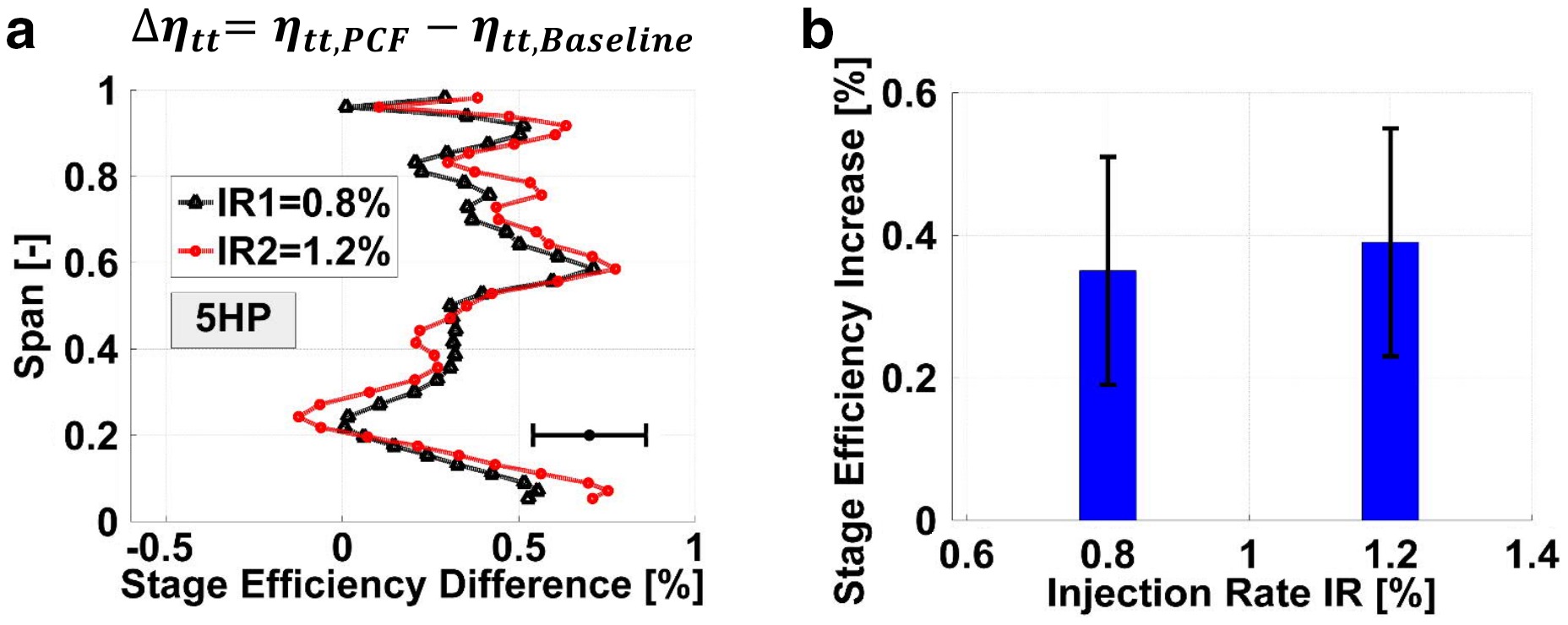
By averaging over the whole measurement grid, the integral values of the total-to-total stage efficiency are obtained. The absolute increase in stage efficiency integral values by changing from the baseline to the PCF geometry is depicted in Figure 4. For both rim seal purge flow injection rates an improvement in the integral values are found whereas a moderately higher increase is found for the high injection rate case IR2. The purge flow features increase the integral efficiency value by 0.35% for IR1 and 0.39% for the IR2 case, respectively.
Furthermore, a purge flow sensitivity study on the integral values shows a 19% lower sensitivity of the stage efficiency with respect to the injected amount of rim seal purge flow for the PCF. In case of the baseline geometry, the stage efficiency sensitivity with respect to purge flow was found to be −0.53% per percent of injected mass flow whereas the PCF case provides a sensitivity of −0.43% per percent injected mass flow.
Rotor inlet and rim seal exit flow field
The presented aerodynamic performance study needs to be complemented by investigating the flow field at rotor inlet, considering the aforementioned design intention of the PCF.
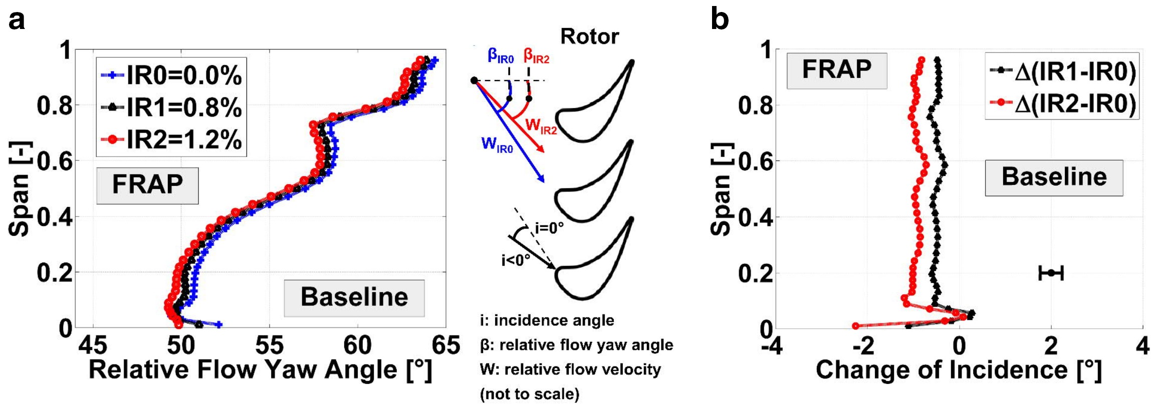
In Figure 5, the mass- and circumferentially averaged relative flow yaw angle distribution at rotor inlet is presented. The effect of injecting rim seal purge flow into the main annulus flow is presented in Figure 5, highlighting that across the whole span, a reduction of relative flow yaw angle is measured by increasing the purge mass flow from 0.0 to 1.2%. The highest rim seal purge flow case shows a reduction of relative flow yaw angle up to 1° at mid-span and 2.3° in close vicinity to the hub, respectively. A reduction of relative flow yaw angle at rotor inlet induces negative incidence on the rotor leading edge (Figure 5). A schematic of the velocity triangles at the rotor leading edge provides a qualitative explanation on the flow field effect (Figure 5, right).
Figure 5.
Mass- and circumferentially averaged relative flow yaw angle at “R in” for (a) purge flow sensitivity and comprehensive schematic and (b) change of incidence.
In Figure 6, the impact of the PCFs is shown by comparing the PCF radial distributions of the relative flow yaw angle to the one of the baseline geometry for the design point at IR1 = 0.8%. The strongest impact of the PCF is seen close to the hub where an increase of 1.4° is found (Figure 6) whereas for the rest of the span, the change of the relative flow yaw angle fluctuates around zero.
Figure 6.
Mass- and circumferentially averaged relative flow yaw angle comparison at “R in,” indicating (a) span-wise distribution and (b) change in relative flow yaw angle.
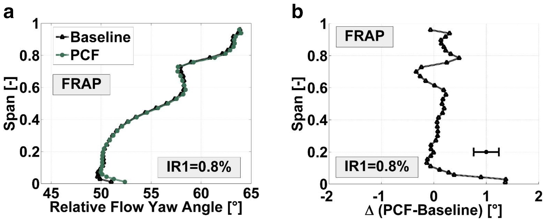
Overall, the PCFs have a beneficial impact on the negative rotor incidence provoked by the injection of purge flow. The relative flow yaw angle distributions of the PCF case implies that the features installed at the rim seal exit counteract the misalignment of the low momentum cavity fluid with the main annulus flow.
When rim seal purge flow is injected from the hub cavity into the main annulus flow, not only the direction of the fluid differs, but also the magnitude of the absolute circumferential velocity. The associated viscous shear layer generates entropy due to dissipation of the velocity gradients. Based on that, the radial distribution of the mass- and circumferentially averaged absolute circumferential velocity is investigated in Figure 7. The presented values are normalized by the rotational speed of the rotor at the hub. The span-wise consideration has been extended into the hub cavity which reveals the circumferential velocity down to −20% span. The effect of purge flow is depicted in Figure 7, showing a gradual decrease of the absolute circumferential velocity over the full span by increasing the purge flow form IR0 = 0.0% to IR2 = 1.2%. The most pronounced reduction is found in the upper part of the hub cavity from 0 down to −20% span. The radial gradient of the absolute circumferential velocity across the rim seal interface has been found to increase up to 48% by increasing purge flow from 0.0 to 1.2%.
Figure 7.
Mass- and circumferentially averaged normalized absolute circumferential velocity for (a) purge flow sensitivity and (b) impact of PCF at rim seal interface.
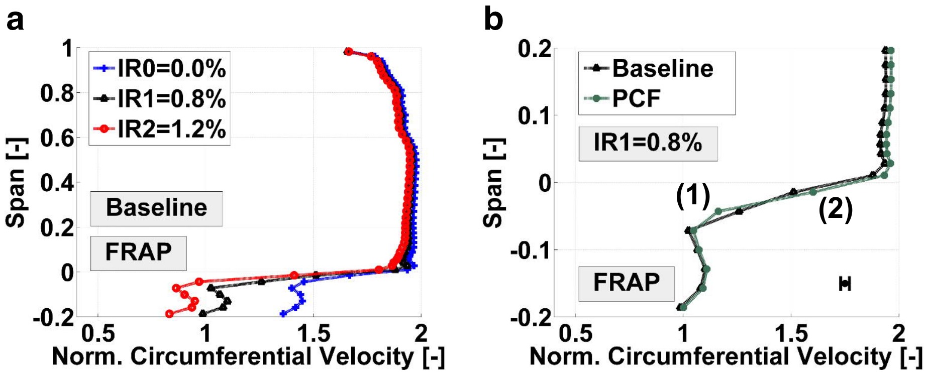
The effect of the PCFs on the absolute circumferential velocity is shown in Figure 7 for the design point IR1 = 0.8%. The figure provides a close-up view on the interface between the hub cavity and the main annulus flow. Of specific interest is the region below the hub from −5 to 0% span where at location (1), a deceleration of the flow is found compared to the baseline. This effect is most probably associated to the stator-sided control features (flow enters the groove). On the other hand, at location (2), the flow is accelerated compared to the baseline case which was intended in the design of the features. Comparing the velocity gradients across the hub region, reveals that the PCF reduces the radial gradient of the absolute circumferential velocity by 11%.
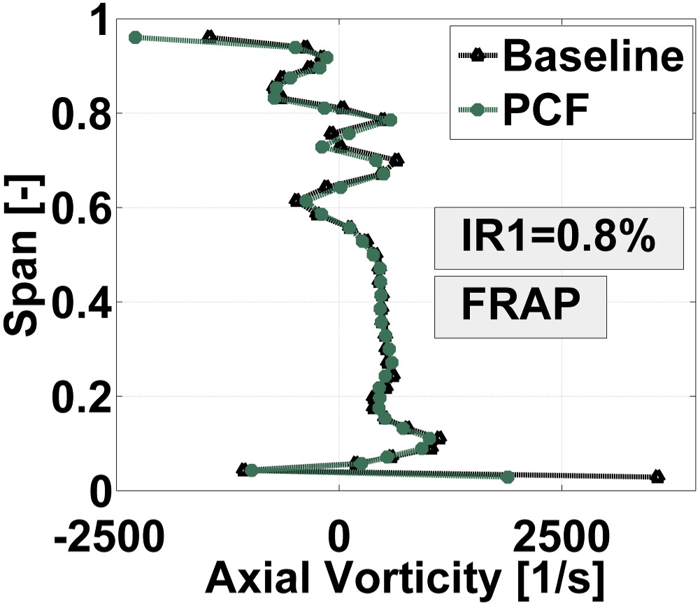
The impact of the reduction in circumferential shear is visible in the vorticity level close to the rim seal interface. Specifically, the circumferential shear has a first order impact on the axial vorticity. Therefore, the circumferentially and mass-averaged axial vorticity is shown for both rim seal designs in Figure 8. The plot indicates that at the rim seal exit strong positive axial vorticity is present which is the signature of a vortex formed by the interaction between cavity fluid and main annulus fluid. The positive impact of the PCFs is visible in this location where a reduction in axial vorticity of 48% is observed. This clearly implies that reducing the tangential shear at the rim seal exit results in a significant reduction in the strength of the vortex.
Figure 8.
Mass- and circumferentially averaged axial vorticity for IR1 = 0.8% and both rim seal designs.
The total pressure levels associated to each rim seal design are analyzed. In Figure 9 and Figure 9, the contour diagrams of the time-averaged normalized total pressure is presented for both rim seal designs and IR1 = 0.8%, indicating the regions where the secondary flow structures of the upstream located stator are present. The hub secondary flow structures of the first stator are located at around 10% span (0.6 stator pitch), whereas the tip passage vortex and tip trailing edge shed vortex are found between 60–80% span (0.75 stator pitch). Additionally, the wake of the first stator is identified by an inclined band of lower total pressure.
Figure 9.
Time-averaged normalized total pressure for IR1 = 0.8% at “R in” for (a) baseline geometry, (b) PCF and (c) mass- and circumferentially averaged profiles.
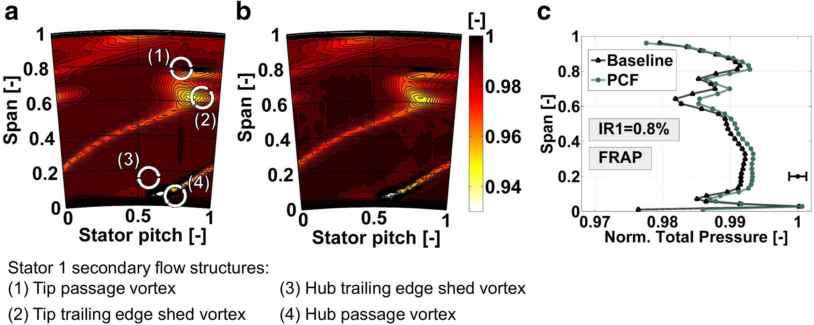
The mass- and circumferentially averaged absolute total pressure profiles for both rim seal designs are presented in Figure 9. The values are normalized by the total pressure at the turbine inlet. Comparing the baseline geometry and the PCF case, a clear increase in absolute total pressure is observed over the full span for the PCFs. The most pronounced increase of 1% is found at around 1% span. At around 65% span, an increase of 0.4% is found. Overall, the PCFs seem to lower the total pressure losses downstream of the first stator and specifically in close vicinity to the hub.
The previous investigations of the rotor inlet flow field suggest that the PCFs have a beneficial impact on the rotor inlet flow field. However, it has been reported by 20 and 12 that an increase in the purge flow swirl coincides with a reduction in the sealing effectiveness against hot gas ingestion which is driven by the circumferential pressure non-uniformity induced by the presence of the rotor blades. In the absence of hot gas ingestion measurements, a quantitative investigation of the mass flow exchange between main annulus flow and rim seal is performed by analyzing the time-resolved radial velocity at the rim seal exit measured with FRAP. Figure 10, presents the time-space plots for the normalized radial velocity for both rim seal designs at 1% span. The values are normalized by the rotational speed of the rotor at the hub. The time axis covers three consecutive rotor blade passing events and the space axis covers one stator pitch. Positive radial velocities indicate that flow is leaving the hub cavity towards the casing of the machine whereas negative radial velocity indicates that flow is entering the hub cavity (towards the axis of the machine).
Figure 10.
Time-space plots in the absolute frame of reference of normalized radial velocity at 1% span and IR1 = 0.8% for (a) baseline, (b) PCF, (c) cut through time at 0.25 stator pitch.

Both plots show a vertical band of positive radial velocities at around 0.75 stator pitch. Within these bands, spots of pronounced positive radial velocities are found which are modulated by the rotor blade passing. These zones of high positive radial velocities are the signature of the purge flow leaving the hub cavity. Therefore, most of the purge flow is leaving the hub cavity at around 0.75 stator pitch. At this location, the hub secondary flow structures of the upstream stator 1 are present (Figure 9) which benefit the intrusion of purge flow into the main annulus by locally reducing the static pressure at the rim seal exit. The stator 1 secondary flow structures seem to decide where the purge flow is leaving the hub cavity whereas the rotor decides when the purge flow is leaving the hub cavity.
Around 0.25 stator pitch, zones of moderate negative radial velocities are found for both, the baseline as well as the PCFs. This indicates for the given purge flow rate of IR1 = 0.8% zones of ingress. Again, this effect is modulated by the rotor blade passing, suggesting that the potential field of the rotor leading edge is interacting with the upstream stator. By comparing the time-space plots of the baseline and PCF case, the peak positive radial velocity at around 0.75 stator pitch is increased for the PCF case by about 2%. The negative radial velocity zones at around 0.25 stator pitch shows similar level of negative velocity which is pointed out in Figure 10.
Based on the available data, the modified rim seal design shows the potential of keeping similar level of ingestion blockage by increasing the aerodynamic performance of the turbine.
Comprehensive flow model — Tangential shear reduction at rotor inlet
The main driver that has been identified in order to improve the flow effects at rotor inlet have been the following:
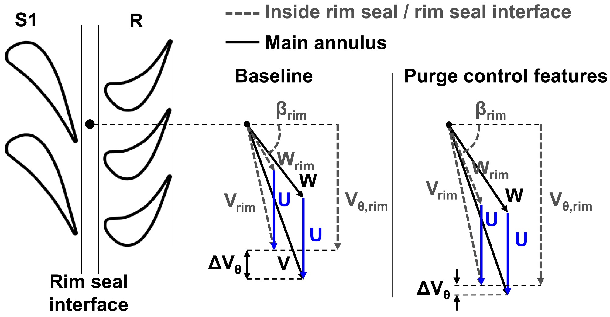
Counteract reduction in relative flow yaw angle (especially increase of relative flow yaw angle at rim seal interface βrim) provoked by rim seal purge flow and hub secondary flow structures by aligning cavity flow closer to main annulus flow. Therefore the negative incidence is reduced at rotor inlet.
Accelerate flow in circumferential direction (increase of ΔVθ) and reduction of tangential shear (reduced ΔVθ). This leads to lower axial vorticity levels and lower total pressure losses close to the hub.
Both aspects are depicted in a flow model (Figure 11) which highlights the main drivers listed above by means of rim seal and main annulus velocity triangles for both rim seal designs. One should consider the difference of the relative flow yaw angle at the rim seal interface βrim and the different levels of the tangential shear indicated by the difference in tangential velocity ΔVθ from baseline and PCF geometry.
Rotor exit flow field
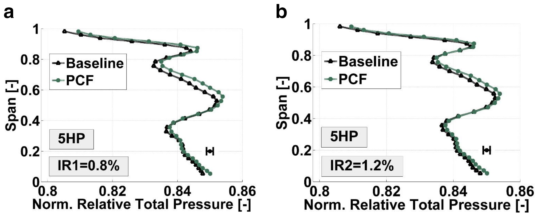
In order to complement the flow field study, the time-averaged flow field at rotor exit is investigated. In Figure 12, the mass- and circumferentially averaged normalized relative total pressure is depicted for the purge flow cases IR1 = 0.8% and IR2 = 1.2% measured with 5HP. The relative total pressure profiles reveal the performance increase by means of reduced losses in the relative frame of reference. Specifically, the region between 50–80% span, shows an increase in relative total pressure up to 0.5% for the PCF case (IR1 = 0.8%). This trend is in agreement with the increase in total-to-total stage efficiency presented in Figure 4. A relative total pressure increase up to 0.3% (IR1 = 0.8%) in close vicinity to the hub is shown when the PCFs are installed. Not only the mid-span and hub regions are affected by the change of the rim seal exit geometry, but also the tip region.
Figure 12.
Mass-averaged normalized relative total pressure for both rim seal geometries at rotor exit for (a) IR1 = 0.8% and (b) IR2 = 1.2%.
The mass-averaged flow investigation needs to be supported by the circumferentially resolved flow field in order to reveal zones of improvement. In Figure 13, the contour diagrams of the normalized relative total pressure in the rotating frame of reference are shown for both rim seal exit geometries and nominal purge flow injection IR1 measured with FRAP.
Figure 13.
Time-averaged normalized relative total pressure in rotating frame of reference at “R ex” for IR1 = 0.8%. (a) Baseline, (b) PCF and (c) highlighted increase of relative total pressure due to PCF.
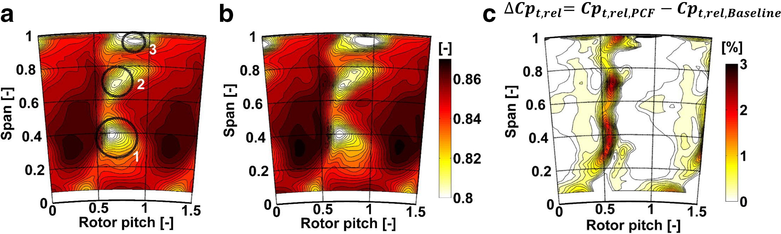
The rotor hub secondary flow structures are observed around 40% span (zone 1). The traces of the tip passage vortex (zone 2) and the tip leakage vortex (zone 3) are seen at 70% span and 95% span, respectively. By comparing Figure 13 and Figure 13, the PCFs do not lead to a radial displacement of the secondary flow structure loss cores. The beneficial impact of the PCF is found in Figure 13 where the time-averaged increase of relative total pressure in percentage is presented. Regions of increase in relative total pressure up to 3% are located along the span where the rotor wake and the trailing edge shed vortices dominate (40 and 70% span). The reduction of negative incidence on the rotor leading edge, leads to a reduction of the rotor profile losses which is demonstrated in Figure 13 by highlighting the regions of highest improvements induced by the PCFs.
Applicability of purge control features for various turbine designs
The presence of cavities inherently provokes a velocity deficit in circumferential direction and therefore a reduction in tangential shear is targeted in most of state-of-the-art rim seals. For the applicability of the proposed features to other turbine designs, the number of features per stator and rotor pitch would need to be consistent to the presented geometries since both stationary and rotating features are clocked to the trailing edge and rotor leading edge, respectively. Therefore, the total number of features is linked to the blade and vane count. Furthermore, the features have shown to increase the aerodynamic performance for nominal and high rim seal purge flow injection rates of 0.8 and 1.2% of the turbine mass flow. This indicates the potential to operate under different engine representative sealing mass flows and gain higher aerodynamic efficiency. The results show the capability of the features to counteract the tendency of higher negative incidence on the rotor leading edge, especially in close vicinity to rim seal interface where the hub secondary flow structures are interacting with the purge flow. Therefore, the features have a beneficial impact when higher strength of the hub secondary flow structures is expected. This might be the case for turbine designs without non-axisymmetric end wall contouring, high turning stators and low aspect ratio blade rows.
The results presented in this work cover aerodynamic considerations with first investigations in terms of hot gas ingestion. Furthermore, the proposed features at the rim seal exit require further thermal and mechanical design assessment, with specific emphasize on hot gas ingestion measurements for implementation in the real-engine environment.
Conclusions
Based on the presented experimental results, the following conclusions can be drawn:
The rim seal exit swirl and tangential shear built up by the velocity deficit of the cavity flow with respect to the main annulus flow have been identified to be the drivers to enhance aerodynamic performance.
In the design process of a rim seal exit geometry, the reduction in circumferential velocity deficit needs to be complemented by imparting sufficient radial momentum against hot gas ingestion. The PCFs described in this work suggest a geometrical solution for accelerating the cavity fluid radially outwards without leveling out the beneficial effect of reduced circumferential shear by increased losses due to higher purge flow penetration.
The aerodynamic performance analysis of the modified rim seal design presents an increase in the total-to-total stage efficiency by 0.4% for nominal and high rim seal purge flow injection rates by keeping the same turbine blading as for a baseline geometry.
The results presented at rotor inlet imply that the suggested features might be used in other turbine designs which are dominated by pronounced hub secondary flow structures, such as low aspect ratio blade rows and stators designed for high turning.
Overall, the work proposes a geometrical solution at the rim seal exit in order to overcome the trade-off between aerodynamic performance increase and penalties in hot gas ingestion blockage that is applicable for different turbine designs.
Nomenclature
Variables
cp
specific heat for constant pressure [J/(kg*K)]
Cp
normalized pressure coefficient [-]
IR
rim seal purge flow injection rate [%]
ṁ
mass flow [kg/s]
M
torque [Nm]
N
rotational speed [rpm]
p
pressure [Pa]
T
temperature [K]
U, V, W
rotor, absolute and relative velocity [m/s]
γ
ratio of specific heats [-]
η
efficiency [-]
π
pressure ratio [-]
ω
rotational speed [rad/s]