
Introduction
Defining the maximum loading achievable by gas turbine engines has been the main topic of research in the field of internal aerodynamics since its advent, in the early 50 s. The higher sensitivity of compressors to losses and instabilities has made their design the most aerodynamically critical in aircraft engines. Every work aimed to forecast the performance of compressor stages provides correlations based either on extensive data from test rigs or fundamental flow phenomena, as stated by Hall et al. (2012). During these years of research, more and more experimental data have been created, and analytical models have been implemented with more sophisticated correlations and, eventually, numerical data available from CFD solvers. This has brought along the generation of highly reliable design tools for the preliminary design of conventional axial compressor stages. However, this is not valid for axial compressor stages with passive and/or active flow treatments, which form a specific family of machines. Among these, stands the design of stages with tandem vanes. Only recently, Giannini et al. (2023) and von Jeinsen et al. (2024) described how the correlations available for single airfoils differ in the presence tandem airfoils: Quasi-2D investigations have shown the relative insensibility of tandem vanes to increased loading levels, and have shown how, depending on whether the solidity or the diffusion factor is kept constant, the best operating point lays at a degree of reaction value of 30% and 55%, respectively; Quasi-3D investigations have indicated that tandem airfoil arrangements offer superior performance compared to single configurations when the rotor DeHaller number is below 0.7.
Brent and Clemmons (1974) experimentally investigated an axial compressor stage with tandem rotors and proved that the 50/50 load split tandem configuration was capable of achieving the target pressure ratio and efficiency. The first application of tandem rotors on a high-speed machine, characterized by a relative inlet tip Mach number of 1.6, was described by Keenan et al. (1969) and Burger and Keenan (1971). However, the use of the double circular arc profiles for the tandem setup did not bring the expected improvements, and the tandem design resulted in a lower efficiency value than the target one. Bammert and Staude (1980) provided an experimental investigation of a four-stage, highly-loaded, high-reaction axial compressor. Starting from the design and section-wise analytical optimization of the profiles, extensive investigations were made by Bammert and Beelte (1980) which ultimately lead to the definition of guidelines for the design of machines with tandem airfoils. Bammert and Staude (1981) suggested, at the time, employing only reaction stages to maximize the benefit of tandem configuration, only mentioning that the stator vanes should feature thick leading edges to deal with their associated increase in flow turning.
Research on tandem airfoils has then been mainly focused on defining design criteria for 2D design and off-design conditions; an extensive literature review on the topic can be found in McGlumphy et al. (2009). Consequently, a series of axial compressor stages with tandem rows has been designed using more recent turbomachinery design techniques, and subsequently tested: the work of Tesch et al. (2014) described the flow structure of a tandem stator with an experimental investigation of a one-and-a-half axial compressor stage; Eshraghi et al. (2014) designed and numerically investigated a highly-loaded stage with tandem rotor and stator vanes, confirming the higher pressure rise capabilities despite a loss in isentropic efficiency at the design point against the equivalent single vanes stage of approximately 3%; Hopfinger and Gümmer (2019) described the multi-stage behavior of an axial compressor with tandem stators by means of numerical investigations; Foret et al. (2021) experimentally verified a transonic compressor with variable stator vanes in tandem arrangement to demonstrate the potential of the tandem configuration with respect to increased stage loading; Kumar and Pradeep (2020) showed a numerical investigation of a low-speed machine with tandem rotors which testified higher performance with respect to the equivalent single rotor stage at design point in terms of pressure ratio and isentropic efficiency. The decrease in performance of the stator, combined with the double tip leakage flow in the tandem rotor, resulted in the single stage exhibiting higher performance under off-design operating conditions; Baojie et al. (2022) extended the diffusor analogy of Koch (1981) and experimentally investigated a tandem rotor-stator stage to show the advantages at low flow coefficients and high loading levels. While the high-loading capacity of tandem airfoils was once again confirmed in the stage environment, the issue of secondary and endwall flows was not. In particular, it seems from the literature that most machines have been designed by strictly comparing them with conventional stages to validate the potential of the tandem arrangement.
More recent works have tried to tackle the issue of high secondary losses in tandem vanes of axial compressor stages in different ways: Giannini et al. (2022) investigated the improvements achievable by a three-dimensional robust optimization of a modern tandem shrouded vane, showing how innovative tandem configurations can reduce the near-endwalls losses of the stator and raise the isentropic efficiency of the stage; Straccia et al. (2022) provided an extensive literature review and general guidelines on the use of the non-axisymmetric endwall contouring in tandem shrouded vanes, highlighting its limited effectiveness with decreasing leakage flow levels; Eckel et al. (2023) exposed the limitations of the reference axial compressor stage with a tandem shrouded stator and found improvements by implementing part-span tandem vanes, i.e., hybrid vanes.
The present study starts from an already designed one-and-a-half-stage low-speed axial compressor stage with tandem vane stator and single blade rotor and it performs a multi-row optimization at different operating points to show the potential still to be unlocked by this configuration in terms of stage parameters and novel tandem arrangements. The starting point is given by an already validated assumption of using tandem vanes while trying to find improvements using multi-operating point optimization, without constraining any of the parameters to an equivalent conventional stage. After having described the test case under investigation and the numerical setup, the aerodynamic improvements are shown by comparing the optimized configuration to the reference. Thanks to the multi-stage arrangement of the reference machine, the benefits are also validated in the three-and-a-half stage environment. Finally, the results are compared to the works available in the literature, to derive future guidelines for the design of axial compressor stages in the presence of tandem vanes.
Test case
The reference geometry is a one-and-a-half stage, low-speed axial compressor featuring a shrouded tandem stator and a shroudless rotor. The stage has been developed at the Institute of Turbomachinery and Flight Propulsion of the Technical University of Munich. It comprises an Inlet Guide Vane (IGV), a Rotor, and a Tandem Stator. The main stage characteristics are shown in Table 1. The clearance levels and the cavity geometry are set to model the usual relative clearance levels of high-pressure rear stages, making the current study operating conditions as close as possible to these types of machines. The initial one-and-a-half stage configuration has then been extended to a three-and-a-half configuration by duplicating the existing rotor and stator geometry to stages two and three, as per Hopfinger and Gümmer (2019).
Numerical methodology
All calculations reported were conducted with TRACE 9.3.312, a 3D cell-centered finite volume Reynolds-averaged Navier-Stokes solver, which is being developed at the DLR Institute of Propulsion Technology in cooperation with MTU Aero Engines. More details on TRACE can be found in Ashcroft et al. (2010) and Becker et al. (2010). The spatial discretization scheme of the Navier-Stokes equations was set to the Fromm scheme with the VanAlbadaSqr flux limiter, guaranteeing second-order accuracy in space. The simulation boundary conditions were imposed as predefined total pressure, total temperature, and velocity direction spanwise distributions at the inlet, coupled with the imposition of a fixed mass flow rate at the outlet of the domain. The variation of the working point across the stability range was achieved by varying the mass flow rate at the outlet. The imposed radial distribution of total pressure at the inlet had a deficit in the upper and lower 20% section, which models the growth of the boundary layer thickness across previous stages, being the stage under investigation aerodynamically projected into the rear block of a highly loaded high-pressure compressor stage. The same approach was used in Heinichen et al. (2011). A single-vane passage per row was simulated, using non-reflecting mixing planes at the interfaces between adjacent blade rows. At the interface between the hub cavity and the stator vane, the standard zonal interface approach of TRACE was used. A CFD simulation was deemed converged when the sum of the residuals of the governing equations, the standard deviation of the mass flow rate, and the total pressure value of the stage reached the desired limit value of 1 × 10⁻⁶. The meshes of every single row passage were generated with NUMECA Autogrid5 version 13.1rc. The mesh creator was chosen for its ability to create an optimally structured mesh for tandem blades in a very robust way, making it suitable to be implemented in optimization routines. The topologies chosen for the IGV and the rotor were the classical H-O-H, while, for tandem stator meshing, a mixed topology based on the default handler for tandem configuration of Autogrid5 was applied (see NUMECAInternational, 2013). Around each blade of the tandem, an O mesh was generated, while, at the inlet, outlet, and the interfaces with the seal leaking passage, a structured H mesh was used. In every region of the domain a value of
Table 2
Assessment of numerical model accuracy through grid convergence index (GCI) values.
| Mesh | Nodes | h | ||||
|---|---|---|---|---|---|---|
| N1 | 16,793,168 | 0.0391 | 1.3826 | 1,03,595 | 1.03654 | |
| N2 | 63,54,512 | 0.0540 | 1.4236 | 1,03,588 | 1.03641 | |
| N3 | 22,02,704 | 0.0769 | 1,03,574 | 1.03628 |
| (P) | ||||
|---|---|---|---|---|
| 1,03,600 | 1.8642 | 0.0084 | 0.01047% | |
| 1.03675 | 1.8253 | −0.0198 | 0.02470% |
Optimization setup
The optimized geometries investigated in this work have been obtained from an in-house developed optimization software, called ATOMIC. The software has already been used and validated in previous works, such as the one of Straccia and Gümmer (2021) and Giannini et al. (2022). ATOMIC uses the meta-heuristic optimizer AutoOpti, developed by DLR, as an optimization algorithm. AutoOpti is an MPI-parallelized multi-objective optimizer, that has been developed at the DLR’s Institute of Propulsion Technology with a focus on turbomachinery applications; more information on the optimizer can be found in Siller et al. (2009) and Voß et al. (2019). The biggest challenge the optimizer had to deal with was the high number of optimization variables coming from three different blade rows which individually have a different influence on the objective functions at the three different operating points analyzed. For this reason, a high number of initial sampled members through the Latin hypercube sampling (LHS) has been chosen, 500. After that, the use of the high-fidelity Kriging surrogate model allowed a speed-up of the optimization routine: the surrogate model provides a prediction of the members’ results and it was continuously updated and improved during the optimization based on the database of the currently generated members. One of the possible issues that could have been encountered was reaching a “sink region” of local minima, from which the optimizer would have not been capable to create newly promising members. For this reason, the evolutionary strategies were chosen as a combination of different models: Mutate, Gradient, Expected Improvement, and Volume Gain. The probability of a new member being created by a certain evolutionary strategy was imposed, and controlled during the optimization to make sure that the standard deviation of the best member evolution was constantly increasing. The same indicator, together with the Cumulative Volume Gain, has also been used to define the stopping criteria of the optimization, which corresponded to a state where the optimizer was not capable to tangibly improve the objective functions imposed anymore.
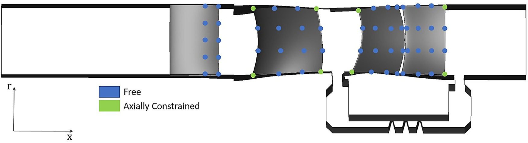
The parametrization of the geometry has been obtained through the discretization of the airfoils using Non-Uniform Rational Bezier Surfaces, NURBS. This means that the surfaces were described by a discrete number of variables in space, called control points, whose movements in the axial or circumferential direction defined the geometrical variations to be imposed on the airfoils surface. Thus, the deformation was generated defining a couple of values for each control point of the camber line which represent the magnitude of the imposed variation and the associated direction. More information on the geometrical parametrization can be found in Giannini et al. (2022). Considering that the front portion of the IGV was not included in the optimization variables, an overall number of 79 free parameters was used. The choice of not including the thickness in the optimization variables has been dictated by its inherent lower influence on low-speed cases compared to high-speed cases, and, indeed, to save some computational effort. Graphical visualization of the current geometrical parametrization, together with the mentioned optimization variables can be qualitatively seen in Figure 1. The shape of the endwalls, the rotor tip gap, and the cavity of the shrouded stator were kept unaltered and not included in the optimization. The maximum variation of the control points has been limited to ensure they do not exceed the mixing plane location of each vane. Additionally, with regards to the stator, the control points are constrained to prevent collisions between the front and rear vanes, and bounded by the cavity meridional location. Moreover, the leading edge and trailing edge control points associated to the endwall sections of the rotor and the stator have been set free to vary only in circumferential direction, to keep the aero-block constant and guarantee that the length over which mixing occurs between the rows remains constant. The geometries for stage number 2 and 3 have then been generated by duplicating the geometries obtained in the optimization routine.
Figure 1.
Meridional View of the Geometrical Parametrization of the IGV, Rotor, and Stator of the Reference Compressor.
The final choice of constraints, objective functions, and optimization variables used in the optimization routine is summarized in Table 3. The constraints imposed guarantee that the optimized members do not experience a reduction in losses merely from a reduced work input, thus, total pressure ratio of the rotor, and from a reduced diffusion duty of the stator, i.e., reduced flow turning. The value of 1° for the difference in outlet flow angle of the stator is coherent with standard design practice for multi-stage matching, and agrees with other similar optimizations published in literature like, e.g., the one of Siller et al. (2009). Finally, to avoid that the optimizer may find optimum geometries with unfavorable multi-stage behavior, the radial distribution of the outlet total pressure of the stage is constrained to be as uniform as possible along the span. The objective functions chosen are the polytropic efficiency at design point, and the weighted average of the polytropic efficiency at throttled and de-throttled operating conditions, at 90% and 105% of the design mass flow rate, with greater emphasis on the efficiency during throttled operation.
Table 3.
Details of the optimization setup: constraints, objective functions, and variables.
| Constraints | Objective functions |
| Optimization variables | IGV | R1 | S1 |
|---|---|---|---|
| Control points displacement | 10 | 16 | 32 |
| Control points direction | 5 | 4 | 12 |
Results
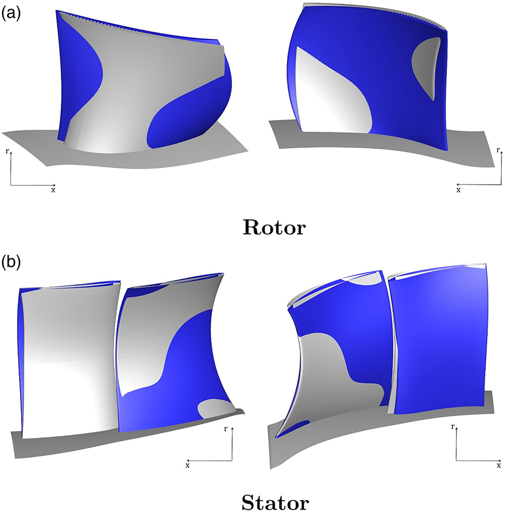
Figure 2 illustrates the three-dimensional geometries of the reference compressor and the optimized member. The optimized rotor exhibits a reduced level of axial sweep (up to
Figure 2.
Three-dimensional View of the Reference (Grey), and Optimized (Blue) Compressor Geometries.
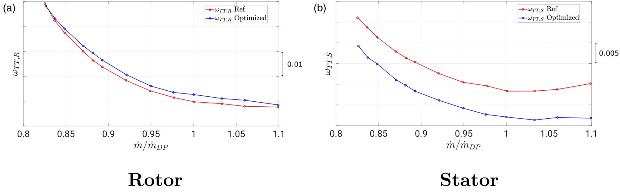
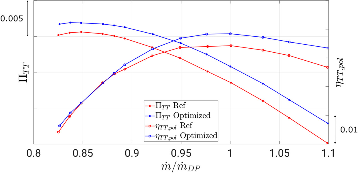
The comparison of the pressure ratio and efficiency characteristics of the one-and-a-half stage is shown in Figure 3. The main benefits of the optimized configuration are an increase in total pressure ratio (with a maximum of 0.05%) which results in an increase in design work coefficient of 2.8%, and an increase in polytropic efficiency (with a maximum of 0.9%). The position of peak efficiency is unaltered, and an improvement of 0.59% is achieved. Moreover, the point of maximum total pressure ratio is now shifted to a lower mass flow rate, indicating a slightly higher operating range of the optimized member. Figure 4 depicts, as an evidence of the aerodynamic improvements of the stage, averaged total pressure loss coefficients of the rotor and stator. Due to the large loss reduction observed all across the characteristic, the tandem stator is primarily responsible for the increase in polytropic stage efficiency. The rotor, however, exhibits a small rise in total pressure losses, indicating that the optimizer on one hand achieved maximum rotor work and on the other hand accounted for the larger loss sensitivity of the tandem stator.
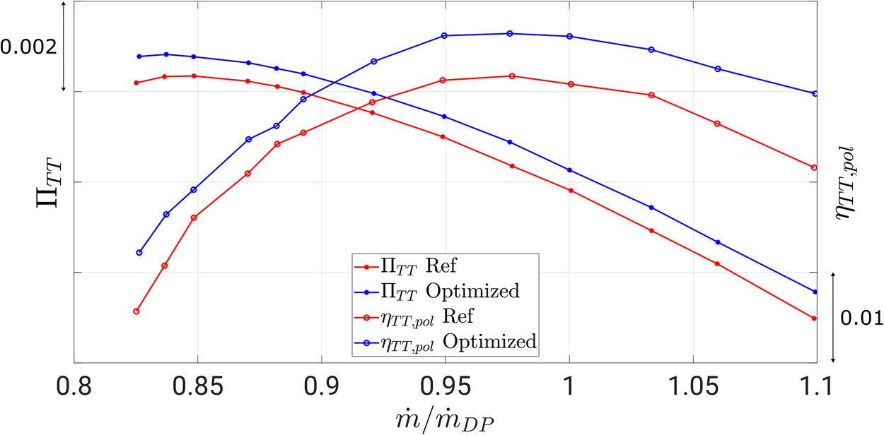
Figure 4.
Comparison of Total Pressure Loss Distributions between the Reference and Optimized Geometries.
These improvements are summarized in Table 4, where the stall margin is calculated as
Table 4.
Comparative performance indicators of reference and optimized compressors.
| Optimized | Reference | ||
| 5.79 | 5.64 | 2.8% | |
| 90.61 | 90.08 | 0.59% | |
| 17.37 | 16.34 | 6.3% | |
| 1.040 | 1.039 | 0.02% | |
| 6.27 | 5.98 | 4.85% | |
| 5.21 | 5.84 | −12% |
The optimized radial distributions of the total pressure ratio of the stage and the degree of reaction are shown in Figure 5: the optimized geometry foresees a clear increase in work input close to the hub and the casing. This is obtained with a slight decrease at midspan, indicating that the main goal of the optimizer is to smoothen the radial distribution of total pressure and re-energize the flow at the endwalls. Quite interestingly, this correlates well with the flow phenomena introduced by Koch (1981) and extended by Auchoybur and Miller (2017), where it was recommended to increase the endwall dynamic pressure if an increase in efficiency, and/or operating range, of the machine is sought. This was possible since the radial flow distributions, usually imposed by the designs coming from through-flow models, were not set as constrains in the optimization routines, as per Phillips (2021).
Figure 5.
Radial Distributions of the Stage Total Pressure Ratio and Degree of Reaction for the Reference and Optimized Compressors.
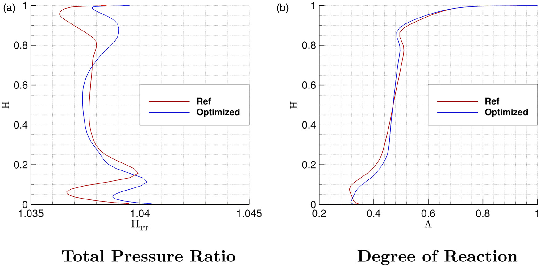
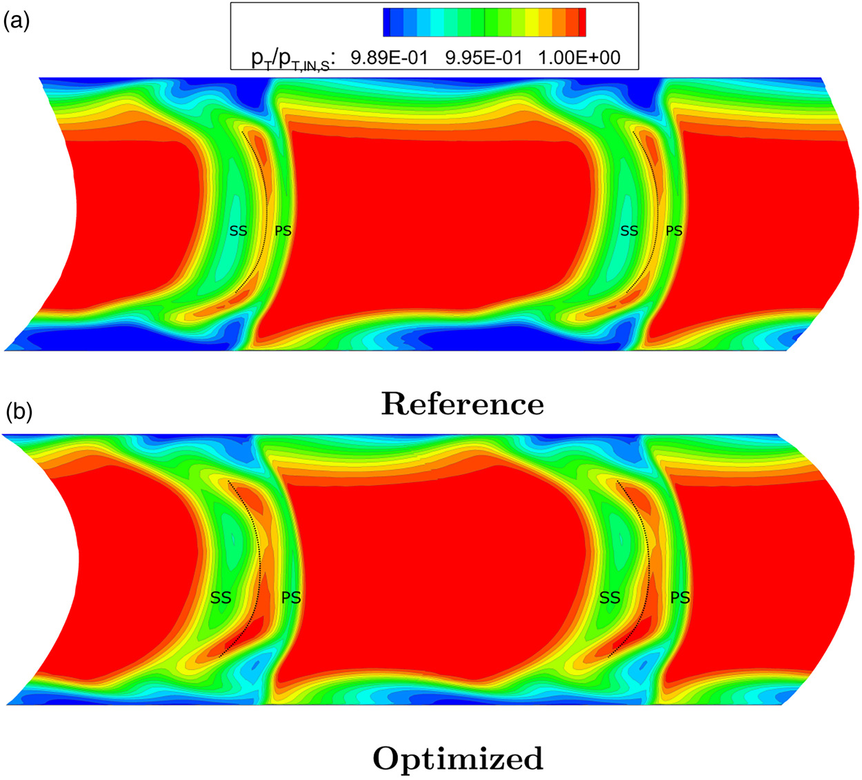
The radial distributions of the degree of reaction in the right-hand-side of Figure 5 clearly show that the optimized configuration foresees a higher degree of reaction (i.e., lower inlet swirl) in the lower half of the channel and a lower degree of reaction (i.e., higher inlet swirl) in the upper half of the channel. This choice correlates to the endwall configuration of the stage, as the optimizer tries to increase the degree of reaction to relieve the static pressure rise of the stator and, consequently, the percentage of recirculating mass flow rate in the cavity. Conversely, the rotor tip gap region benefits from a lower loading correlated to the increase in inlet swirl. It, therefore, appears that the optimized geometry agrees well with the guidelines provided by Yoon et al. (2015), tailoring the inlet swirl distribution according to the optimal value for each section. Similarly, the value of the degree of reaction at midspan is left almost unaltered, as its reference value already agrees with the midspan results of the Q2D investigation of Giannini et al. (2023). Figure 6 depicts the contours of the non-dimensional total pressure at the outlet of the stage. As discussed in Figures 2 and 5, the biggest improvement the optimizer could achieve is the reduction in low-momentum fluid close to the endwalls, achieved by an increased flow energization close to the hub, to counteract the recirculating flow from the cavity, and by an additional flow-turning provided by the rotor at the casing. It can also be appreciated how the regions of high total pressure in the gap have a larger circumferential extent for the optimized configuration: this is a result of the additional loading of the stator unlocked by the optimizer which relates to the 2.7% increase in the vane diffusion factor, and to the increase in work input achieved by the stage.
Figure 6.
Contours of Non-dimensional Total Pressure at Stage Outlet for the Reference and Optimized Compressors.
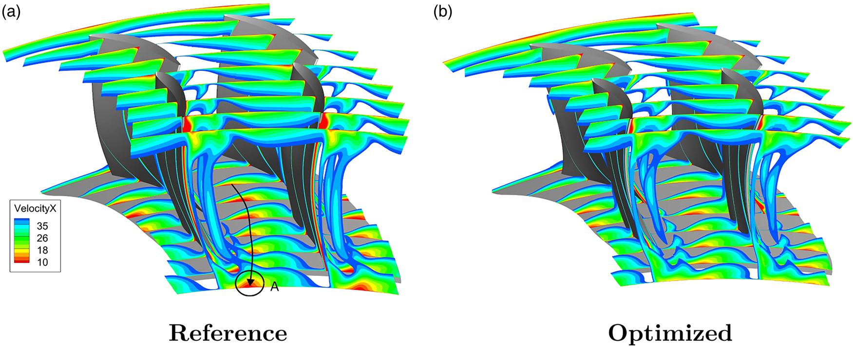
Further details in the flow field are illustrated by plotting axial velocity contours at various axial locations for both the reference and optimized stators in Figure 7. The primary source of losses, deriving from the interaction of the low momentum fluid with the suction side of the rear vane, is considerably mitigated by the optimized geometry. Specifically, the optimized hub geometry appears to obstruct the circumferential migration of this loss core (highlighted on the left-hand side of Figure 7 in black, resulting in the high loss region labeled “A” for the reference case) by employing a larger gap size in the tandem profile at the hub. The efficacy of this modification is supported by the increased flow field energization provided by the rotor. As a result, the loss core is driven to lower channel height percentages, diminishing its magnitude and lessening its negative interaction with the main channel flow in the optimized stator. This corner separation is the principal factor in the observed loss reduction at the hub in the optimized geometry, as evidenced by the stage outlet contours of total pressure in Figure 6.
By comparing the cross-sectional profiles of the optimized tandem vane shown in Figure 8 with those available in published literature, some valuable observations can be made: Eckel et al. (2023) proposed to substitute the tandem setting near the endwalls by closing the gap with a single blade segment to overcome the low effectiveness of the tandem nozzle; Straccia and Gümmer (2021) suggested to make use of the non-axisymmetric hub endwall contouring to de-load the tandem vane where the nozzle flow could not be beneficial.
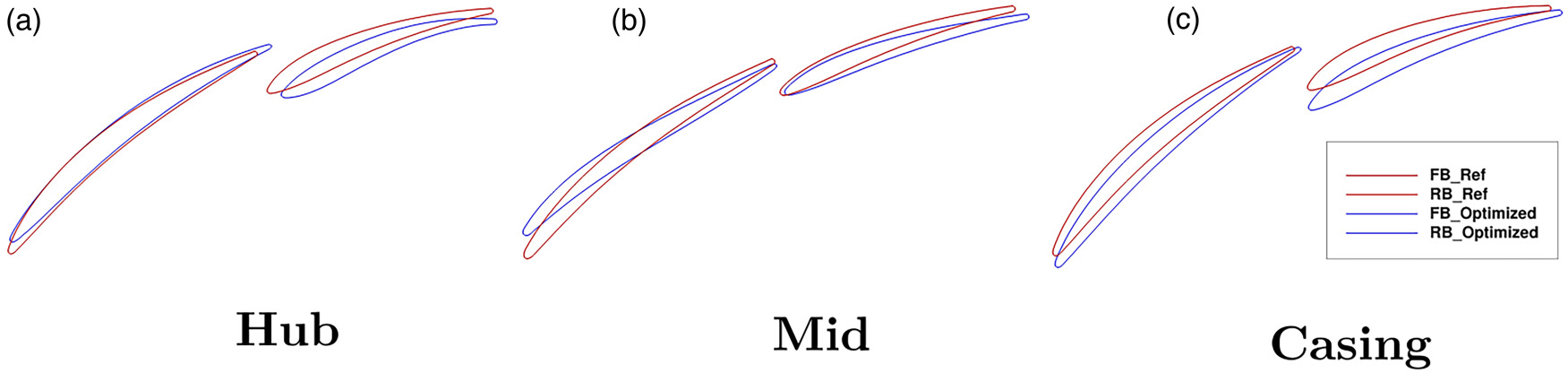
These results indicate how the flow field can be aerodynamically improved if the gap geometries are treated differently at the endwalls than at the midspan section, where the gap flow behavior correlates well with the 2D studies present in literature. The gap area close to the endwalls should, therefore, be increased to account for the lower nozzle effect available in these regions. Thus, the idea of re-distributing the load of the tandem stator along the span, anticipated by Giannini et al. (2022) in the isolated stator environment, is here extended to the one-and-a-half axial compressor stage.
Multi-stage environment
In Figure 9, the swirl distributions provided by the IGV and the outlet swirl of the stage for the reference and optimized geometry are plotted: the choice of constraints shown in Table 3 confirms the desired multi-stage behavior of the optimized stage, and shows an improved matching level with respect to the reference compressor when looking at the 20% and 90% sections. The radial distribution of the stage outlet total pressure confirms the findings of Figure 5, as the optimized radial distribution is smoothened up to the endwall sections.
Figure 9.
Radial Distributions of the Stage Inlet/Outlet Flow Angle and Stage Outlet Total Pressure for the Reference and Optimized Compressors.
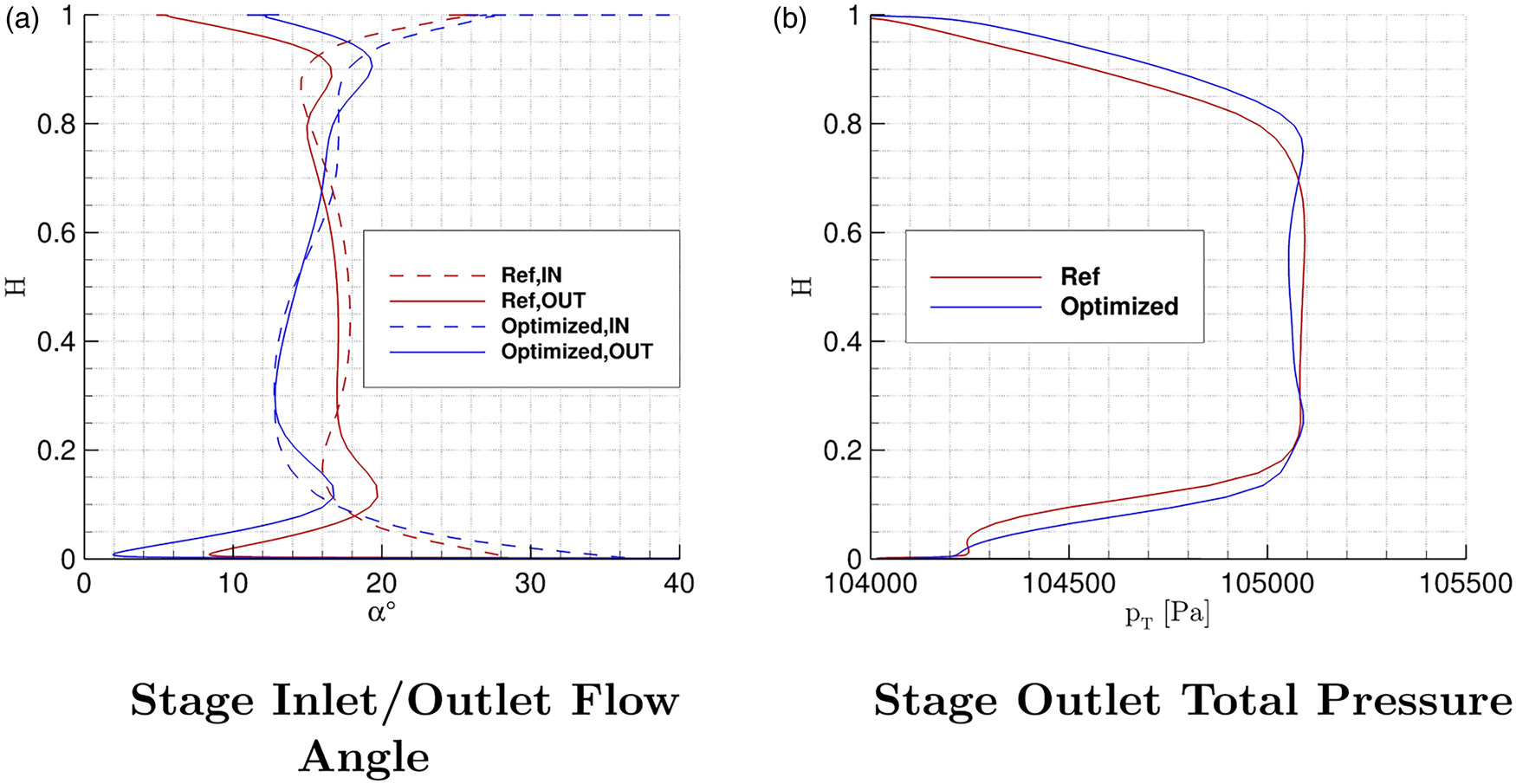
This level of multi-stage matching extends the characteristic curve of the one-and-a-half stage shown in Figure 3 to the three-and-a-half stage configuration plotted in Figure 10: the optimized geometry shows an increase in total pressure ratio (with a maximum of 0.21%) and an increase in polytropic efficiency (with a maximum of 0.76%). The position of peak efficiency is unaltered, and an improvement of 0.46% is achieved. Comparing it with respect to the distribution shown in Figure 3, the biggest advantage of the new multi-stage geometry is given by the increase in work, favoring the applicability of this configuration in future, more compact aero-engines. On the other hand, the increase in total pressure ratio is not accompanied by a similar increase in polytropic efficiency towards stall conditions, value which converges towards the reference one. It, therefore, appears that the benefits of the new tandem configuration are overcome by the increase in endwall blockage when throttling the compressor in the rear stages.
Conclusions
A fully three-dimensional optimization of a multi-stage axial compressor with tandem vanes was carried out. The geometries have been optimized by means of single row airfoils and stage parameters, contrary to standard optimization routines, where the inlet and outlet radial profiles of the different flow quantities are constrained by the results of preliminary through-flow analyses. The optimized configuration obtained has been thoroughly investigated by means of row and stage performance parameters: the characteristic curves have shown how the new geometry provides an increase in stage work coefficient of 2.8%, a slight increase in stall margin, and an increase in isentropic efficiency of the stage up to 0.9% at high mass flow rate values. The constraints imposed on the optimization routines, by means of swirl angle matching and radial distribution of the total pressure at the outlet of each stage, have been shown to be suitable for the multi-stage configuration of the machine. This provided an increase in total pressure ratio of 0.21% and isentropic efficiency up to 0.79%. Moreover, the results of this work can be summarized in the following points:
The radial distribution of the degree of reaction of highly-loaded axial compressor stages with tandem, shrouded stator and shroudless rotor should be chosen consistently with the endwall configuration of the stage. Therefore, an increase close to the hub and a decrease close to the casing should be prescribed. Only at midspan, correlations ad-hoc coming from studies on tandem vanes should be used.
The radial distribution of the rotor work should be prescribed as uniform as possible along the span to allow a flow-energization close to the endwalls; this, already suggested in recent guidelines available in the published literature for efficient axial compressor designs, allows an even bigger improvement for stages with tandem vanes, mostly achievable in the tandem gap regions.
An increase in loading achievable by the tandem vanes can be obtained if the radial distribution of the geometry of the stator foresees an increase in the gap area close to the endwalls, where the additional aerodynamic loading achievable by this unconventional configuration can not be guaranteed as in the midspan section. In this way, the high loss core given by the front and rear vane can be broken down. However, the midspan region can still rely on 2D results, as the flow field in this region is more uniform.
The shape of the optimized three-dimensional tandem vanes indicates that bow and sweep can be very beneficial to reduce the aerodynamic losses of the front vane, consistent with the results of Giannini et al. (2022); however, the rear vane appears to benefit less from three-dimensional stacking laws, as the optimizer tries to reduce the level of sweep and bow to control the radial distribution of the tandem gap area.
At throttled conditions, the isolated re-design of the airfoils of the rotor and the stator could improve only the multi-stage pressure ratio, considering the high blockage values in the rear stages. If the main goal of the designer is to improve the efficiency at low mass flow rates, endwall passive/active control features should be used to effectively counteract this increase in losses.