
Introduction
An increasing demand for more sustainable gas turbines and aero engines requires increasing efficiencies (Krein and Williams, 2012). Higher efficiencies can be achieved by further increasing the pressure ratio and turbine entry temperature (TET). To facilitate a higher TET, the cooling methods and more specifically film cooling has to be further improved. This requires a thorough understanding of the interaction between coolant jet and hot gas. It will enable the development of more efficient thus sustainable gas turbines and aero-engines.
Numerous experimental investigations, predominantly determining thermal film cooling quantities such as adiabatic film cooling effectiveness and ratio of heat transfer coefficients with and without film cooling dependent on various parameters such as blowing ratio
Hale et al. (2000) investigated 90° jets in cross-flow considering parallel and reversed parallel coolant cross-flow. They used flow visualisation, surface heat transfer measurements and numerical simulations to relate flow field and heat transfer, but the operating conditions do not replicate density ratio, free stream turbulence or length scales as they are expected in gas turbines or aero engines. Aga (2009) analysed the influence of flow structures on film cooling parameters for compound angled holes but neglect coolant cross-flow, turbulence intensity and temperature ratio, instead using foreign gas to replicate engine-realistic density ratios. Joint studies of the flow field and thermal film cooling quantities were conducted investigating the effect of freestream turbulence intensity on film cooling ejection at low blowing ratios for cylindrical and fan-shaped holes (Wright et al., 2011a,b; Johnson et al., 2014). Unfortunately, only unity density ratio has been used in their studies which prevents a direct application to realistic engine-like conditions. A good qualitative agreement but large local quantitative differences were observed when comparing flow field and thermal measurement data to numerical simulations (auf dem Kampe et al., 2012). The effect of high free stream turbulence on the flow field was further investigated in Schroeder and Thole (2016), but also neglecting coolant cross-flow.
None of the previously mentioned studies consider coolant cross-flow as well as engine-realistic density ratios and turbulence intensities. Engine-realistic operating conditions are, however, extremely relevant to achieve meaningful insights into the cooling performance and flow field in the regime of hot gas coolant interaction. Therefore, conjoint investigations combining flow field information and thermal film cooling quantities are required considering all relevant dimensionless parameters. Aside from mean flow quantities, the present study shows that the instantaneous flow field is relevant for fully understanding the time-averaged flow fields and thermal film cooling parameters.
Methodology
In this section, the test facility is outlined. Furthermore, the measurement setup and the measurement principles are provided and the uncertainties are discussed.
Test section and measurement setup
The schematic setup of the test section and measurement setup used for the current investigation is displayed in Figure 1. The test section in Figure 1a was constructed for acquisition of adiabatic film cooling effectiveness
Figure 1.
Schematics of test section and measurement setup including FOVs for IRT and SPIV measurements. (a) Schematic of test section containing hot gas and coolant channel including a turbulence grid ➀, boundary layer suction ➁, ejection module ➂, optical access for IRT ➃, thermal measurement plate ➄, IRT camera ➅ and FOV for SPIV ➆; adapted from (Fraas et al., 2017). (b) Schematic SPIV Setup as top view on test section including: ejection module ➀, camera lens ➁, Scheimpflug adapter ➂, camera ➃, light sheet optics ➄, ND:YLF laser ➅ and FOV for IRT ➆; adapted from (Stichling et al., 2021).
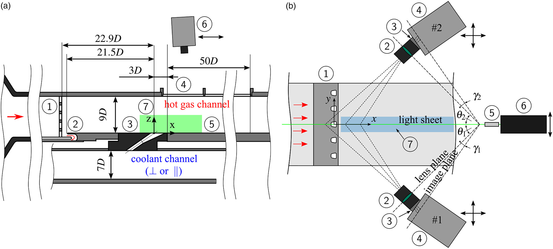
Table 1.
Operating parameters of the test section.
A turbulence grid (Roach, 1987) is placed downstream of the inlet nozzle ➀ and in combination with a subsequent boundary layer bleed ➁ is used to ensure well-defined and engine-like flow conditions at the coolant ejection. Coolant and hot gas channel are connected via the interchangeable ejection module ➂ containing three to five separate film cooling holes aligned laterally at a constant
The test section was adapted to accommodate stereoscopic Particle Image Velocimetry Measurements (SPIV) (Stichling et al., 2021) capturing the field of view (FOV) ➆ indicated by the green area in Figure 1a. The SPIV measurement setup is detailed in Figure 1b using a top view on the hot gas channel of the test section from Figure 1a. Optical access for the SPIV measurement is granted via two fused silica windows (not displayed), one on each lateral wall of the hot gas channel. A light sheet with a thickness of
Silicon oil particles with a mean diameter of
Two geometries are investigated and detailed in Figure 2. The first geometry (Figure 2a) constitutes a 10°-10°-10° laidback fan-shaped (LFH) hole with a cylindrical inlet segment. The cylindrical part of the cooling holes is scaled up by a factor of
Figure 2.
Film cooling hole geometries considered in the current study. (a) 10°-10°-10° laidback fan-shaped hole; (Fraas et al., 2019a). (b) Slot geometry with coolant side plenum-like structure.
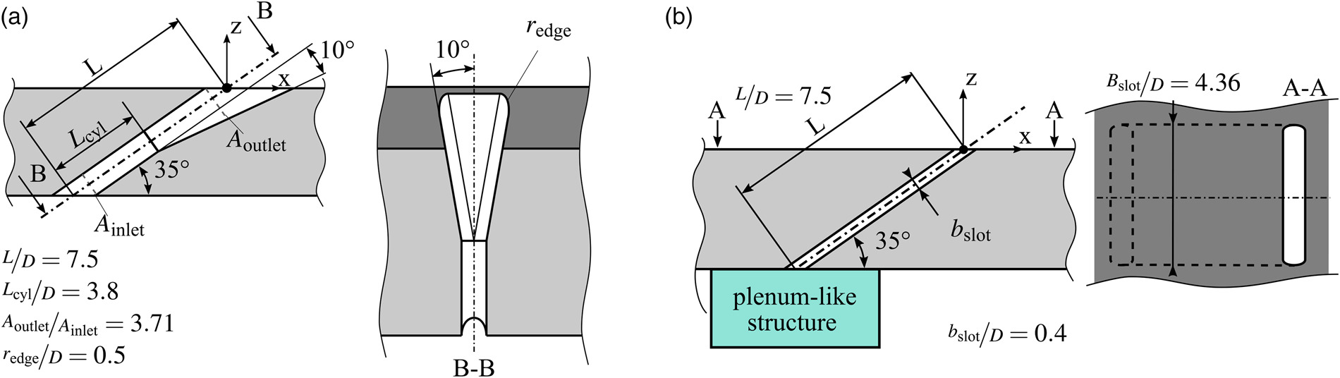
A strong interaction between the individual film cooling jets can be expected for the LFH geometry due to their lateral proximity (Baldauf, 2001) and can be anticipated for the slot geometry as well.
Measurement uncertainties
Detailed information regarding the measurement uncertainties of the flow parameters for both hot gas and coolant channel can be found in (Fraas et al., 2017). The measurement uncertainty, calculated according to (Kline, 1953), is below 12% for the heat transfer coefficient with film cooling
For estimating the measurement uncertainty in the PIV experiments, a method based on correlation statistics (Wieneke, 2015) was used. In terms of absolute velocity, the spatially averaged relative local uncertainty was below 2.2%. The local relative uncertainty was found to be below 5% everywhere except in the close-wall region
Results and discussion
In the following sections the geometries depicted in Figure 2 are analysed with regard to their aerothermal characteristics. For film cooling in gas turbines the most important aspects are the adiabatic film cooling effectiveness, the change in heat transfer due to film cooling and the potentially adverse or beneficial influence of the coolant ejection on the hot gas main flow and therefore the turbine blade aerodynamics. The latter affects the overall performance of a turbine blade and is often assessed globally (Ligrani, 2012; Lanzillotta et al., 2017) rather than for individual film cooling hole geometries. This can be attributed also to a lack of detailed aerodynamic investigations of film cooling hole geometries at realistic boundary conditions.
For the following comparison of the geometries, it should be noted that the blowing ratio of the slot geometry was adapted in such a way, that an equal coolant mass flow per lateral length unit was achieved. So the mass flow ejected along
Adiabatic film cooling effectiveness and heat transfer coefficient
In Figure 3 the spatial distribution of the adiabatic film cooling effectiveness
Figure 3.
Spatial adiabatic film cooling effectiveness η a , W
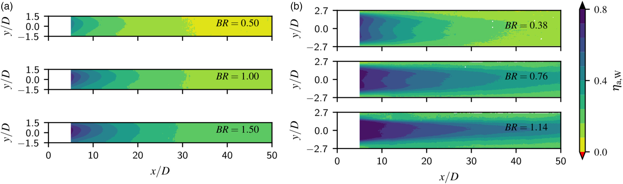
Figure 4.
Laterally averaged adiabatic film cooling effectiveness η ¯ h f = h o
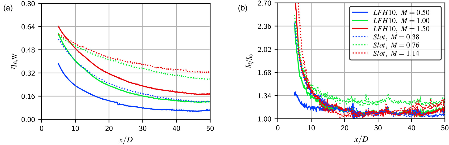
For the slot, two lateral peaks in film cooling effectiveness can be observed for all blowing ratios. Towards higher blowing ratios and in streamwise direction
Comparing both geometries, much higher values of adiabatic cooling effectiveness
Nearly no significant increase in
The laterally averaged ratio of heat transfer coefficients with and without film cooling
Flow field analysis
While assumptions about the underlying aerodynamics of film cooling jets are often based on thermal film cooling parameters, measurements of the velocity field around the coolant-hot gas interaction are required to fully understand the competing effects causing the observations presented so far.
In Figure 5, velocity profiles normalised by the hot gas main flow velocity
Figure 5.
Normalised absolute and wall-normal velocities along wall normal direction for multiple x / D x x / D w x / D
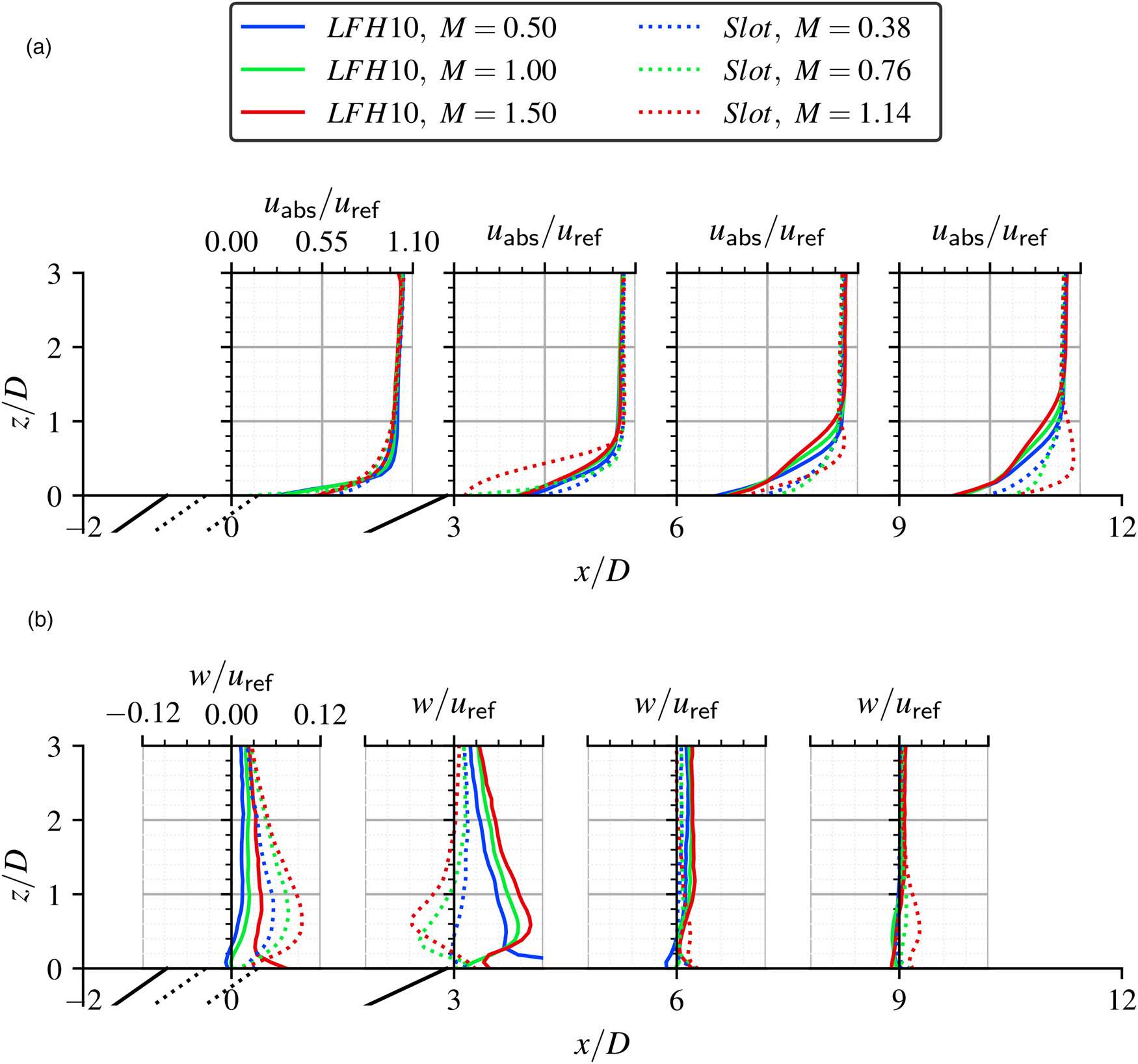
For the absolute velocity in Figure 5a at
Further downstream at
The absolute velocity profiles at
For the slot geometry a strong decrease in velocity towards increasing blowing ratios can be observed at
To understand the volumetric flow field, measurements were conducted at multiple lateral positions for the highest blowing ratio of each geometry by shifting the SPIV setup in Figure 1b in
Figure 6.
Velocity fields in the y , z x / D p / D = 3 x / D = 1 x / D = 1 p / D = 3 x / D = 9 x / D = 9
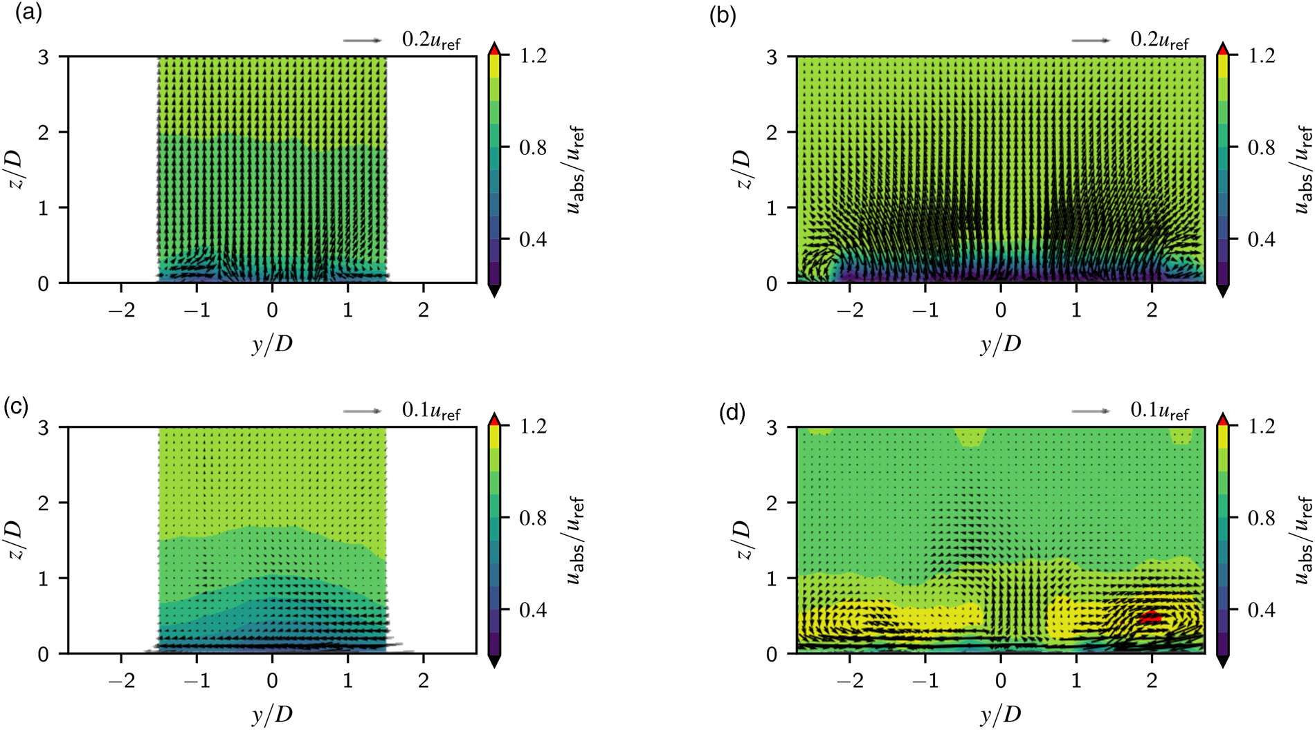
At
In generic jet in cross-flow (JIC) studies its origin is frequently associated with the effect of the jet’s impulse on the cross-flow boundary layer, which would classify the CVP as a far-field phenomenon. Near-field studies indicate a different or at least additionally contributing formation process connected to a tilting and folding of the jet shear layer (Fric and Roshko, 1994; Karagozian, 2014). Numerical studies related to the JIC application in film cooling suggest a vortex pair formation already in the hole which at least contributes to the CVP (Baldauf and Scheurlen, 1996).
The position of the vortices for the current investigation suggest a formation outside the hole but very close to it’s exit in the near-field. For
In case of the LFH10 geometry, no secondary motion related to the CVP can be observed at
For the slot geometry a complex vortex system can be observed at
Figure 7.
Dewarped instantaneous PIV raw images with enhanced coolant seeding for the streamwise, wall-normal centre plane; blowing ratio B R = 1.50 B R = 1.14
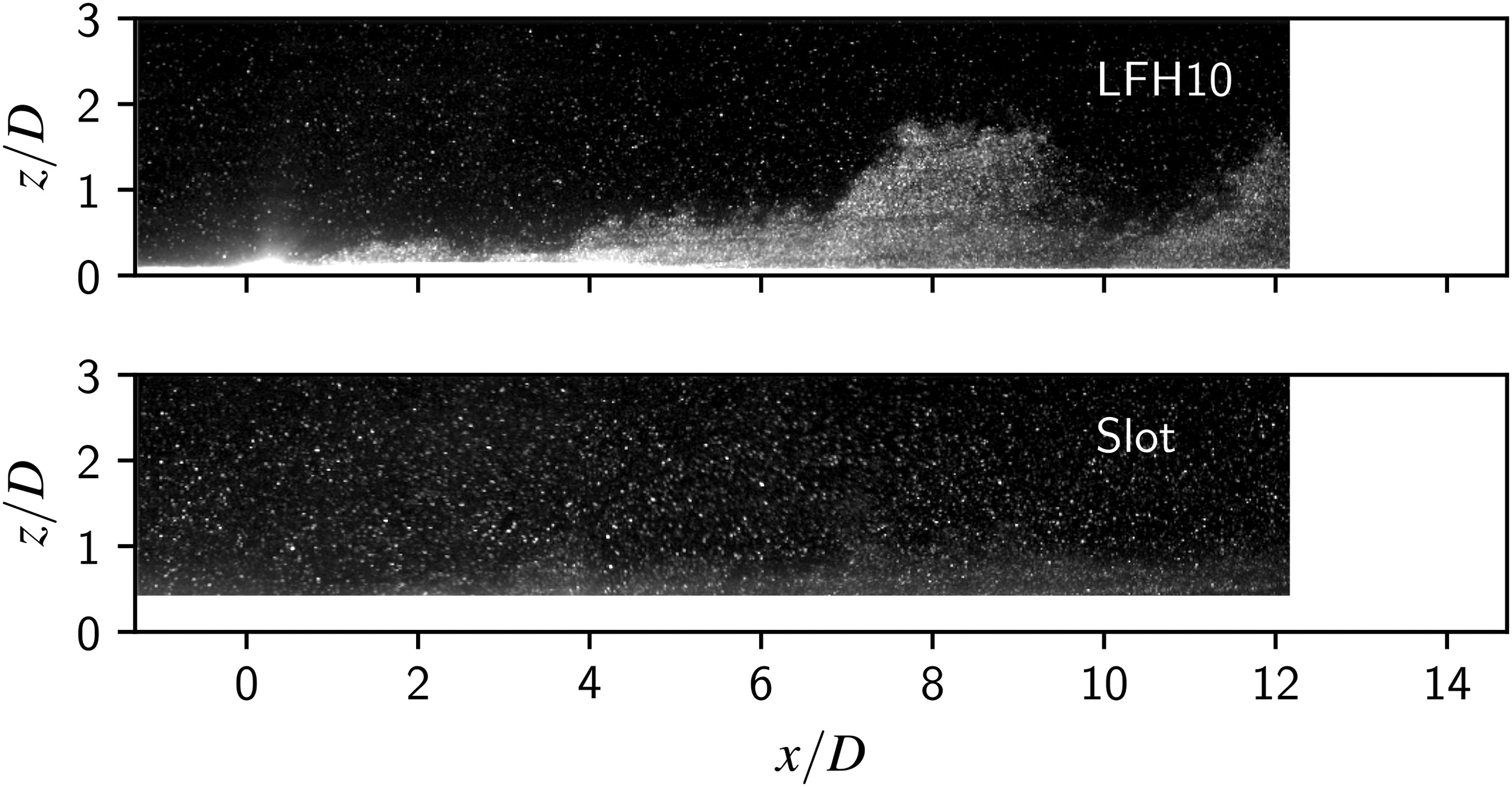
In Figure 7, a clear qualitative difference between the coolant distribution for the different geometries can be observed. Coolant “chunks” are present for the LFH10 geometry, whose streamwise locations vary dependent on the chosen instant in time, whereas a uniform and relatively time-independent coolant distribution can be observed for the slot geometry. While both geometries are subjected to the same turbulent fluctuations in the main flow, the slot geometry seems to be much more robust towards local changes in the main flow velocity close to the hole exit. The instability of the exiting coolant for the LFH10 geometry is likely connected to a flow separation in the laidback section of the diffuser, which strongly responds to the instantaneous main flow boundary condition. The separation of these coolant “chunks” from the coolant jet into the main flow carries coolant away from the wall and effectively reduces the near-wall coolant mass flow drastically. It also indicates a flapping of the jet, which is responsible for creating the coolant “chunks” in the first place. Even if those merge back into the coolant jet again, their temperature would have increased due to the enhanced hot gas main flow exposure and mixing. This further detriments the cooling potential provided by a certain coolant mass flow. This also explains the more rapidly decreasing adiabatic film cooling effectiveness in case of the LFH10 geometry. The stability of the generated coolant jet or coolant film therefore plays an important role in how efficiently a provided coolant mass flow is used.
Conclusion
In the current work two different geometries are analysed based on thermal as well as aerodynamic measurement data to emphasize the importance of a stable and continuous film cooling ejection on the resulting adiabatic film cooling effectiveness. Despite nearly completely suppressing the counter rotating vortex pair, the LFH10 compared to the slot geometry results in much lower laterally averaged adiabatic film cooling effectiveness