
Introduction
Labyrinth seals are extensively used in aero-engines to control the leakage between regions with different pressures to prevent the ingestion of hot gas in the turbine disk cavities and for cooling operations (Chupp et al., 2006). They are comprised of rotating and stationary components. The rotating parts are usually equipped with a series of radial fins while the stationary elements have straight or stepped geometries. The flow is repeatedly forced to pass through small clearances generating kinetic energy that is dissipated in the inter-fin cavity. This process increases the resistance to flow compared to a smooth slot.
The first pioneering studies on seal flutter were conducted during the 60’ and 70’ by Alford (1964, 1971, 1975). His works discuss the cause and prevention of fatigue failures in seals. He identified the importance of the support side of the seal in preventing self-excited vibration. Ehrich (1968) introduced the importance of the knife-edge clearance on the seal stability, but his findings were restricted to the 0th nodal diameter. Ehrich (1968) proposed an analytical model and identified a stability parameter that included the effect of the clearance, the support side of the seal, and the geometry of the inter-fin cavity. The models described by Ehrich and Alford did not take into account the effect of the circumferential flow. Abbot (1981) found that a seal supported on the low-pressure side was unstable only if the mechanical frequency was lower than the acoustic frequency of the seal, and vice-versa. According to Abbot’s criterion, the mechanical to acoustic frequency ratio and the support side of the seal are the only two parameters that control the stability of the seal.
All the previous studies were based on experimental analysis, failure evidence, and often on bulk-flow analytical models. Nowadays, CFD analyses are commonplace both in industry and academia. Mare et al. (2010) conducted a parametric investigation on a multi-finned straight-through seal to investigate the influence of the frequency and the support location on the seal stability. They found that the aerodynamic damping depended mainly on the cavity shape, the mode-shape, and the unsteady pressure phase distribution. Mare et al. (2010) describe the application of a time-marching nonlinear Navier-Stokes solver to the stability analysis of an LP turbine labyrinth seal for two different configurations. The results are compared with Abbot’s stability criterion suggesting that complex seal configurations are not appropriate to be treated with simple stability criteria based on the comparison of the structural and acoustic frequencies. Recently, Miura and Sakai (2019) have compared CFD results with experimental data obtained in an in-vacuum rotating rig. The numerical results show reasonably good agreement with the measurements.
Recently, Corral and Vega proposed a new comprehensive model for seal flutter (Corral and Vega, 2018; Vega and Corral, 2018). The model provides an expression for the work-per-cycle involving two new and additional dimensionless parameters to define the stability map of the seal. All the results of the classical analytical models (Abbot, 1981; Ehrich, 1968) are recovered and conciliated. The results were also extended to stepped-seals Corral et al. (2020). Moreover, it has been identified that the tip labyrinth seal has an outstanding effect on the stability of shrouded turbine rotor blades Corral et al. (2019). The numerical results are compared with the prediction of the Corral and Vega (CV) model corroborating the stabilizing effect predicted analytically. Recently, a new formulation of the baseline Corral and Vega model (2018) accounting for non-isentropic perturbations has been proposed (Corral et al., 2021b). The model redefines the dimensionless parameters described in Corral and Vega (2018) and outlines a more general stability map of the seal. The high sensitivity of the seal stability to differential gapping and the role of the effective gaps and the carry-over coefficient has been addressed recently (Corral et al., 2021a).
This work presents a numerical validation of the CV model for labyrinth seal flutter, including non-isentropic perturbations. The paper is organized as follows. First, the analytical model and the test case are briefly introduced. Secondly, steady-state results are presented. Finally, the results of the numerical simulations are compared with the predictions of the analytical model. It is concluded that the numerical results present a high degree of matching with the predictions of the high-order analytical model in a broad range of operating conditions provided that the model is properly informed with the seal steady-state obtained from a RANS solver.
Governing equations
The baseline CV model (Corral and Vega, 2018) solves the linearised integral form of the mass-conservation equation of the inter-fin cavity and the differential form of the momentum equation in the circumferential direction. The circumferential unsteady variations of the flow are retained in the model but the mean flowfield is deemed spatially constant for a given circumferential position. The unsteady perturbations due to the seal vibration are assumed isentropic and varying only circumferentially. The isentropic condition is replaced by the energy equation of the inter-fin cavity in the higher-order version of the model (Corral et al., 2021b). The flow through the seal fin is deemed quasi-stationary since the thickness of the fin tip is much smaller than the characteristic size of the seal. Moreover, the process is assumed to be adiabatic and the work associated with the seal rotation in the inter-fin cavity is neglected. The seal vibration is introduced imposing that the spatio-temporal variations of the gaps, H, and the volume of the seal have the form of travelling-waves. Finally, the linearised equations are solved seeking solutions in the form of travelling waves as well.
The dimensionless out-of-phase component of the unsteady pressure of the cavity of the higher-order model is
where the dimensionless pressure is defined as
and where

Equation (1) reduces to a simple expression in the isentropic baseline model (Corral and Vega, 2018) since
where the auxiliary variable
In general,
The dimensionless gap or torsion centre includes the effect of the pivot centre of the vibration mode-shape, r, the seal clearance, H, and the geometry of the seal (see Figure 1) and is defined as
In the isentropic formulation of the problem (Corral and Vega, 2018), because of its simplicity, the parameters
where
The dimensionless work-per-cycle,
where
The dimensionless work-per-cycle depends on four non dimensional parameters
As described in Corral et al. (2021b) the dependence of the
Numerical setup
A simplified geometry consisting of a straight-through labyrinth seal with a single inter-fin cavity has been constructed to assess the accuracy of the CV model. This model only accounts for the work exerted by the seal in the inter-fin cavity land which frequently is the dominant one. Therefore the actual shape of the adjacent cavities is irrelevant for this purpose. It is acknowledged that the neighbouring cavities, especially in or close to the acoustic resonances, can exhibit a large level of unsteadiness that eventually can influence the inter-fin cavity. Especial attention has been paid in this work to avoid such resonances to ease a clean comparison between the model and the CFD analyses. A schematic view of the model used in this study and the geometric details of the seal are shown respectively in Figure 1 and Table 1. Special care has been taken in sizing the upstream and downstream cavities. Both cavities have been designed to ensure a uniform pressure at the inlet and outlet of the seal and to avoid any eventual acoustic resonance in the frequency range of the simulations.
Table 1.
Physical geometric parameters of the seal inter-fin cavity.
| Cavity radius ( | Nominal gap ( | Length ( | Height ( |
|---|---|---|---|
| 554 mm | 0.2 mm | 15.8 mm | 10.1 mm |
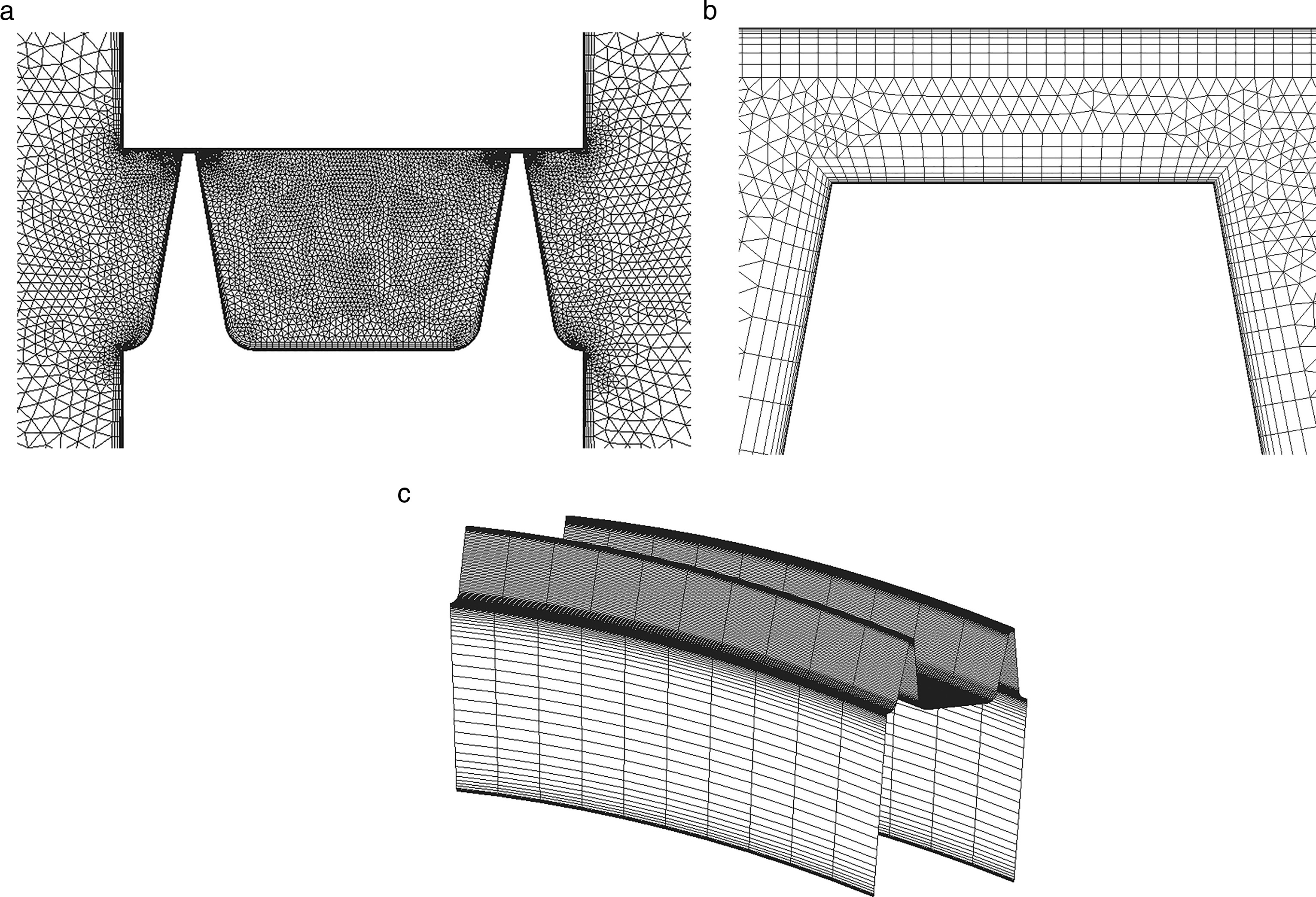
The CV model has been already partially assessed on the tip-shroud of an LP turbine (Corral et al., 2019) using a well-validated frequency-domain linearized Navier-Stokes solver (Corral et al., 2003; Vega and Corral, 2016). In this work, a two-dimensional hybrid grid has been constructed in the meridional plane of the seal and extruded in the circumferential direction to form triangular prisms and hexahedra. A grid sensitivity study has been conducted by checking the convergence of the mass flow rate and the mean static pressure in the inter-fin cavity. Hereafter a model with approximately 350,000 points was chosen (see Figure 2). The standard
Figure 2.
Outline of the computational domain around the seal (a), mesh detail around the fin tip clearance region (b), and azimuthal overview (c).
Mode-shape definition
The dimensionless work-per-cycle,
Results
Steady state
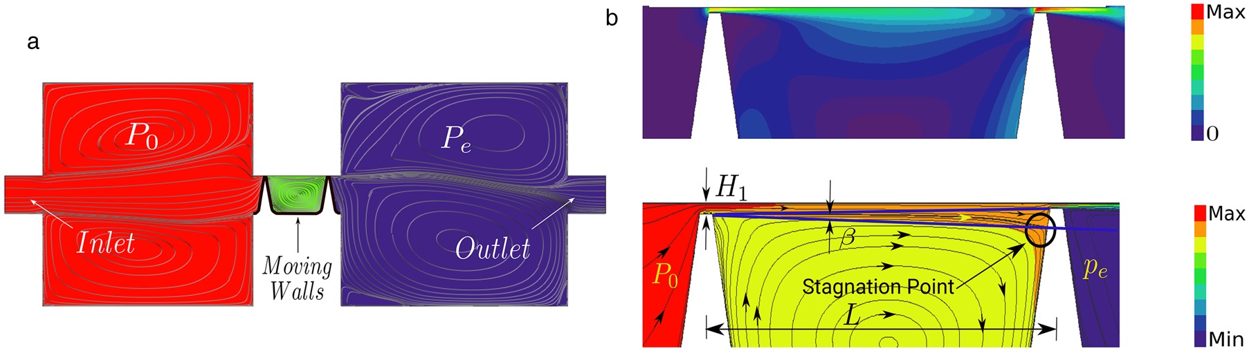
The steady results obtained from the simulations are presented next. For all the simulations of this work, a non-rotating seal is assumed to reduce the uncertainties in comparing with the model. The high-pressure and low-pressure cavities are designed to act as plenum chambers. Both cavities are characterized by large low-Mach re-circulation zones. (see Figure 3b (top)). The streamlines displayed in the Figure 3b (bottom) show that the wall jet created in the first fin impinges onto the second one separating the inter-fin cavity into a thin wall-jet region and a large enclosed vortex. The wall-jet mixing increases with the distance dissipating his kinetic energy. The wall jet reaches the downstream clearance and part of its kinetic energy is recovered. The static pressure in the inter-fin cavity is nearly constant consistently with the CV model. The model has a built-in steady-state value however, the estimate of the static pressure within the cavity, the effective gaps, and the energy carried over to the downstream fin are obtained averaging the steady CFD solution.
It was observed that the discharge coefficient of the baseline case changes from the first to the second fin. To properly compare the numerical results with the model predictions we need to incorporate the effective gaps in the formulation. The discharge coefficient is defined as the ratio between the actual mass-flow,
where
Work-per-cycle: 0th nodal diameter
In this section, the prediction of the analytical model is compared against the numerical results obtained with a 2D linearized Navier-Stokes solver (Corral et al., 2003) for the 0th nodal diameter. The seal motion associated with this mode-shape does not create acoustic waves propagating in the azimuthal direction, and therefore there are no circumferential variations of the flow. The analytical expression of the work-per-cycle for the ND 0 is obtained from 1 for values of
Figure 4.
Dimensionless work-per-cycle contour plots of the 0th nodal diameter as a function of the dimensionless frequency, Ω ~ e ~ h ′ π T = 2.0 ( h ′ = 2 ) ( W ~ cyc = 0 )
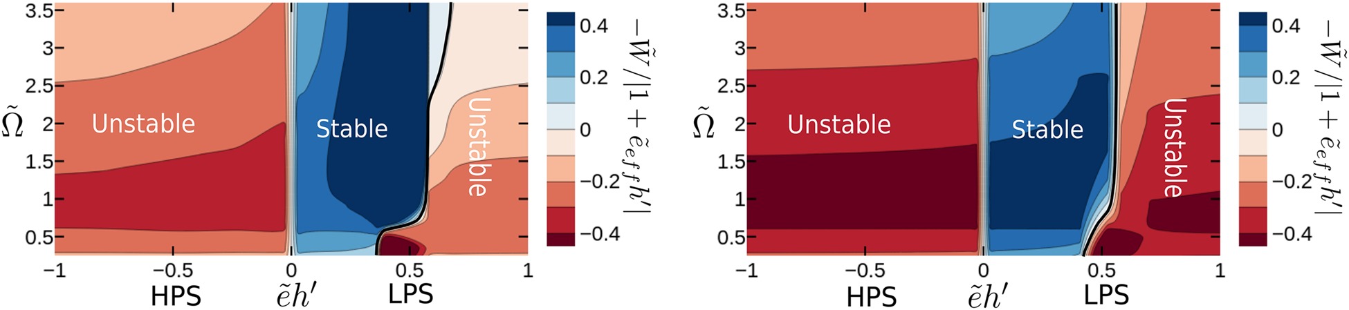
The stability map shown in Figure 4 might seem weird at first glance, in fact, the seal is stable only in a narrow range of the nondimensional torsion centers
shows that for high values of the nondimensional height,
The higher-order model (Corral et al., 2021b) predicts that for low-frequency of vibrations
Figure 5.
Influence of the inlet/outlet cavities: Out-of-phase component of the unsteady pressure for π T = 2.0 ( | e ~ h ′ | ≪ 1 ) | e ~ h ′ | ≫ 1
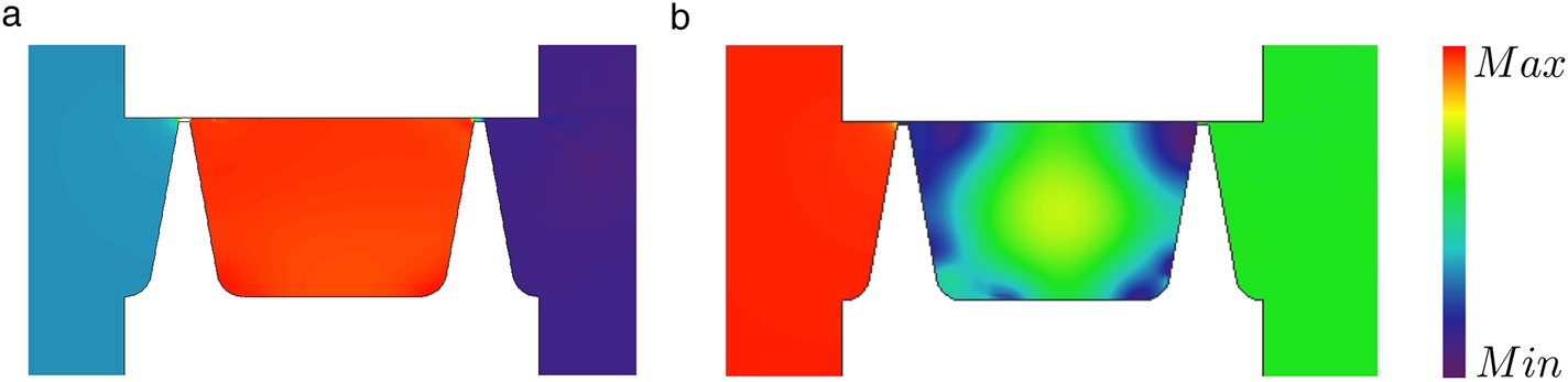
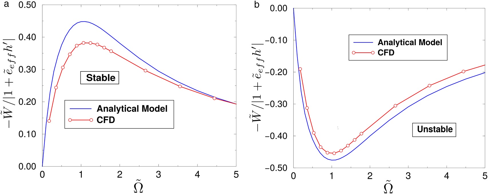
Figure 6 shows the comparison of the CFD results with the analytical prediction for two selected torsion centers. The simulations have been obtained for a pressure ratio of
Figure 6.
Nondimensional work-per-cycle for a two-fin straight seal for selected torsion centers and 0-th nodal diameter ( π T = 2 ) e ~ h ′ = 0.06 ( r / L = 1 ) e ~ h ′ = − 0.23 ( r / L = − 4 )
Work-per-cycle: Circumferential variations
The simulations of this section have been obtained by keeping the pressure ratio and the non-dimensional discharge time,
which is a generalisation of the expression derived in Corral and Vega (2018). The nondimensional group
Figure 7 shows the general stability map for a two-fin labyrinth seal operating at a pressure ratio of
Figure 7.
Dimensionless work-per-cycle contour plots as a function of the reduced frequency, St, e ~ h ′ , π = 1.5 Ω ~ = 3.35

Table 2.
Steady state data derived from CFD non-linear analysis. The pressure ratio and the nondimensional frequency are kept constant, π T = 1.5 Ω ~ = 3.35
| 0.23 | 0.97 | 0.93 | 0.83 | 21.000 | 3.32 |
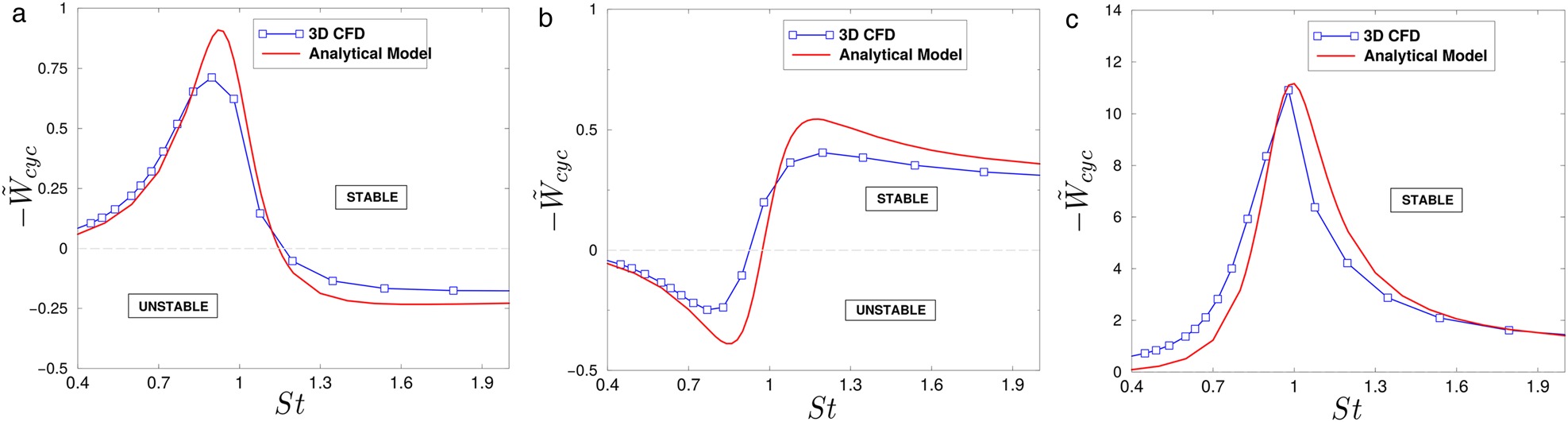
To check quantitatively the accuracy of the analytical model comparison with a selected set of CFD results is included. Figure 8 displays the non-dimensional work-per-cycle as a function of the non-dimensional frequency ratio,
Figure 8.
Dimensionless work-per-cycle as a function of the frequency ratio, St π T = 1.5 Ω ~ = 3.35 e ~ h ′ = − 0.4 ( r / L = − 4 ) e ~ h ′ = 0.05 ( r / L = 0.5 ) e ~ h ′ = 0.7 ( r / L = 7 )
Concluding remarks
The aeroelastic stability of labyrinth seals under different working conditions and vibration mode-shapes has been compared with the predictions of an analytical model. It has been found that it is essential to inform the model with the correct parameters derived from the steady-state numerical simulations, especially the effective gaps and the amount of kinetic energy carried over to the downstream seal, which are the most critical parameters to allow a proper comparison with the model. The non-isentropic perturbations described in the high-order model have been observed in the CFD simulations at low vibration frequencies as expected. The largest discrepancies between the numerical results and the model predictions have been obtained when the discharge time of the seal is much smaller than the characteristic time of the vibration
Nomenclature
Speed of sound in the cavity
CV
Corral and Vega (2018) Model
Seal pressure function
Fin clearance
HPS
High-Pressure Side
Seal cavity length
LPS
Low-Pressure Side
Mass flow rate
Nodal diameter
Cavity static pressure
Exit static pressure
Inlet total pressure
Cavity effective total pressure
Torsion center position
Cavity radius
Cavity height
Vibration-to-acoustic frequency ratio
Cavity center
Work per cycle