
Introduction
The world of power generation is changing rapidly. Analyses of future electricity generation predict renewables and natural gas to have the highest growth of all fuels in the coming decades. According to the reference scenario in the International Energy Outlook (2017), their combined share is increasing to 57% in 2040, 26% being covered by natural gas, i.e. gas turbines. As gas turbines are anticipated to play such a major role in the future energy mix, and in the change-over to renewables, it is of utmost importance to further enhance the efficiency and to reduce the emissions of gas turbine power plants. Additionally, gas turbines need to exhibit outstanding fuel and operational flexibility, in order to compensate for intermittent power production from renewables (Wang et al., 2012). In this context, fuel flexibility does not only include strongly varying compositions of natural gas but also less traditional fuels. Two such examples are hydrogen enriched fuels, derived from the storage of excess renewable generating capacity in form of hydrogen, and very low calorific value fuels from waste processes or biomass gasification.
Efficient, ultra-low emission gas turbines are key to meet the global challenges of reliable energy production and to minimise the environmental impact of power generation. The need for efficiency and power increase calls for increasing firing temperatures. This in turn requires extremely short combustion chambers and rapid mixing, so that the post-flame residence times are sufficiently low to keep detrimental NOx emissions below the limits. On the other hand, part-load carbon monoxide (CO) burn-out has to be guaranteed as well, which is diametrically opposed to having short combustors. To accomplish this goal, the reheat combustion principle is best suited. Ansaldo Energia's reheat gas turbines consist of two combustion chambers arranged in series (Güthe et al., 2008; Düsing et al., 2013; Pennell et al., 2017; Zahirovic and Knapp, 2017; Konduri et al., 2019). For such a reheat engine, the second combustor can be switched off allowing the engine to be parked at extremely low loads. This is an unbeatable advantage during the times the renewables satisfy the energy demand. In this scenario, the gas turbine can be operated at very low loads and when required is able to deliver power very fast because it does not need to be switched on first. In contrast to this, single combustor gas turbines cannot be turned down to similarly low levels and eventually would have to be turned off with the disadvantage of requiring longer time to get to base load and penalties in engine lifetime due to start-stop cycles.
In this paper, the reheat concept is explained in general and its benefit to burn highly reactive fuels and/or fuels of different reactivity is shown. In particular the capability of addressing a broad range of fuel reactivity with the same hardware is considered. Different steps in the combustor development process are described. Firstly, reaction kinetics is used to achieve a detailed understanding of the effect of different fuel reactivity on reheat flame stabilisation. This 1D assessment is further developed with CFD models to obtain full-scale burner geometries. Finally, high pressure combustion tests are conducted for validation of the full-scale engine geometry.
Reheat advantage for fuel flexibility
Ansaldo Energia's GT26 and GT36 gas turbines feature sequential combustion technology, enabling higher firing temperatures, lower emissions and increased operational and fuel flexibility.
In the GT26, sequential combustion is implemented with two combustion stages separated by a high pressure turbine: the first stage (EV) operates at pressures over 30 bar, while the second stage (SEV) operates at roughly half of the EV pressure (Güthe et al., 2008). In the GT36 no high pressure (HP) turbine was implemented, nevertheless the sequential combustion concept and its associated benefits were maintained. In this case, the two combustion stages operate at similar pressure (CPSC: Constant Pressure Sequential Combustion) (Pennell et al., 2017).
In a traditional premix gas turbine combustor, a change in fuel reactivity implies a change in flame location. In particular, higher fuel reactivity forces the flame to move upstream, increasing NOx emissions, and potentially overheating the burner, while lower fuel reactivity results in the opposite and pushes the flame downstream, increasing CO and unburned hydrocarbons emissions due to the insufficient burnout time.
Sequential combustion overcomes this issue by adapting the flame temperature of the first stage (FS) while keeping the overall combustor exit temperature constant (Figure 1):
Figure 1.
Flame position control: a change in fuel reactivity is compensated by a change in fuel distribution allowing optimal flame location on both first and second stages.
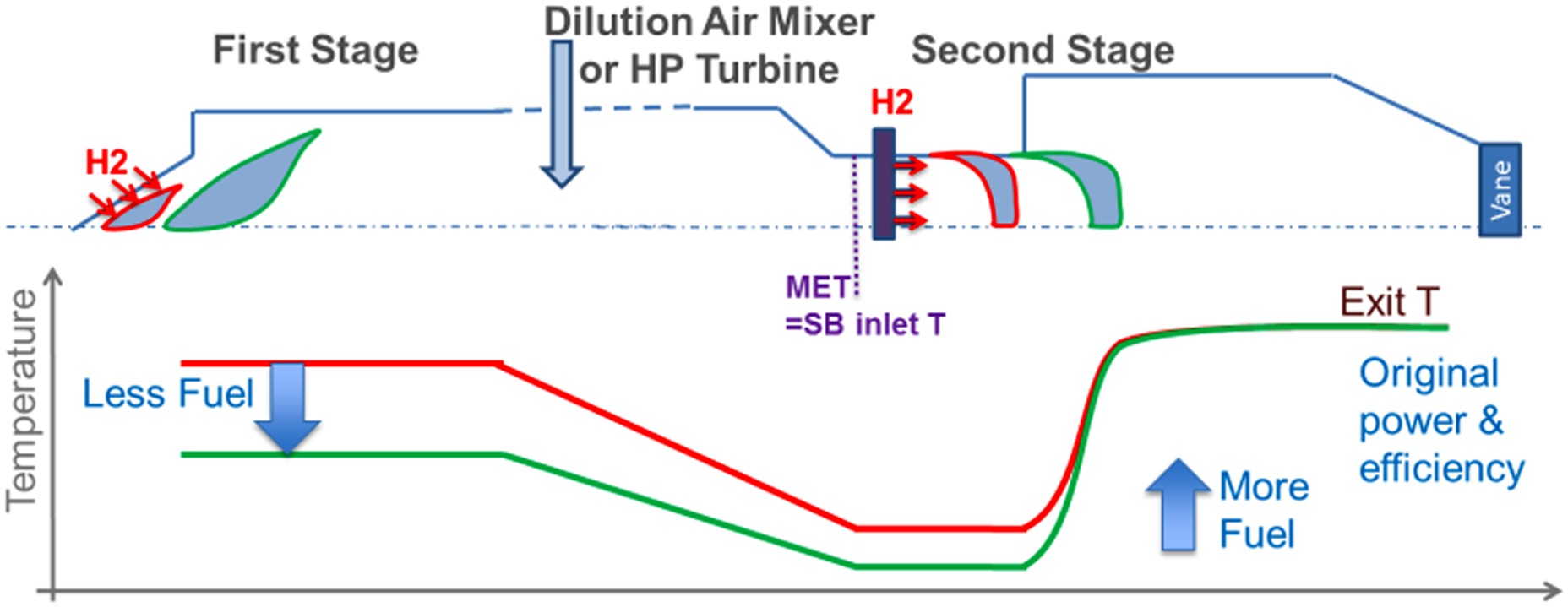
For a more reactive fuel (e.g. fuels containing large quantities of either higher hydrocarbons or hydrogen) the location of the flames would move upstream potentially being too close to the burner exit (the red curves in Figure 1). For a sequential combustion system this is avoided by dropping the first stage flame temperature (green curve). The effect of higher fuel reactivity is compensated by lowering the temperature and as a result the flame is maintained at its optimal location. Consequently, the lower first stage temperature causes also a drop in the second stage inlet temperature called MET = Mixer Exit Temperature (where dilution air mixes with first stage flue gases). Since the sequential burner (SB) flame is mainly auto-ignition stabilised, its flame position is driven by its inlet temperature and not its exit temperature, in contrast to the case of propagation stabilised flames. Therefore a drop of MET compensates the higher fuel reactivity, maintaining the optimal flame location and the original desired flame temperature without compromising engine performance. This also allows the turbine inlet temperature to be held constant.
For a less reactive fuel as e.g. natural gas with minimal or no hydrogen or higher hydrocarbons, the first stage can be operated at a higher temperature. Analogous to the case described above, the change of flame temperature in the first stage compensates the changed fuel reactivity on both first and second stages, again maintaining overall performance and emissions.
Adapting the fuel ratio between first stage and second stage for optimum combustion performance was also extensively applied to high hydrocarbons within GT26 fleet (Riccius et al., 2005; Wind et al., 2014).
Reaction kinetics
In this section chemical kinetic calculations are presented to show the impact of pressure and temperature on the auto-ignition time. It is the auto-ignition time that is the relevant parameter for the second stage operation and understanding its variation with fuel composition allows the targeted range of fuels to be burned in the existing CPSC hardware.
Model description
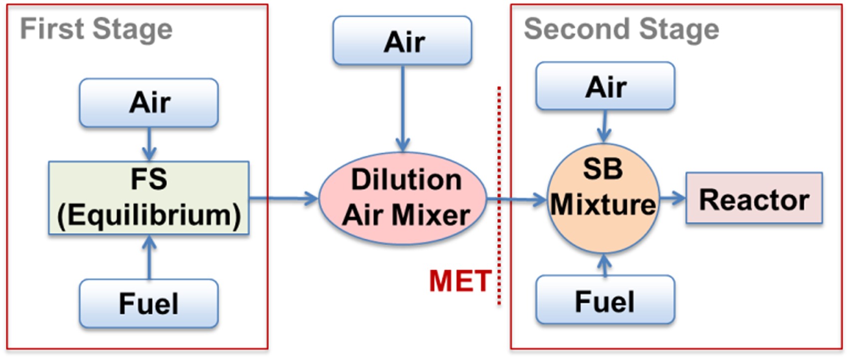
The behaviour of the auto-ignition delay time for various fuel types has been studied in the context of the GT36 CPSC system using chemical kinetic analysis. A reactor network was set up representing the CPSC system as shown in Figure 2. The FS exit temperature is obtained from equilibrium calculations. Mixing then occurs between the output of the FS calculation and dilution air injected downstream of the burner; the resulting mixture defines the MET (second stage inlet temperature). The second stage fuel and cooling air is added into this hot gas mixture for the auto-ignition delay time calculations (SB Mixture). In the situation where the MET changes and the reactor exit temperature is fixed, the air and fuel mass flow rates also change, thus the unburned mixture temperature in the reactor varies. The auto-ignition delay time in the second stage is obtained by running a perfectly stirred reactor (PSR) simulation using Cantera (Goodwin, 2009) with the AramcoMech1.3 reaction scheme (Metcalfe et al., 2013).
Chemical kinetics results
Pressure dependence
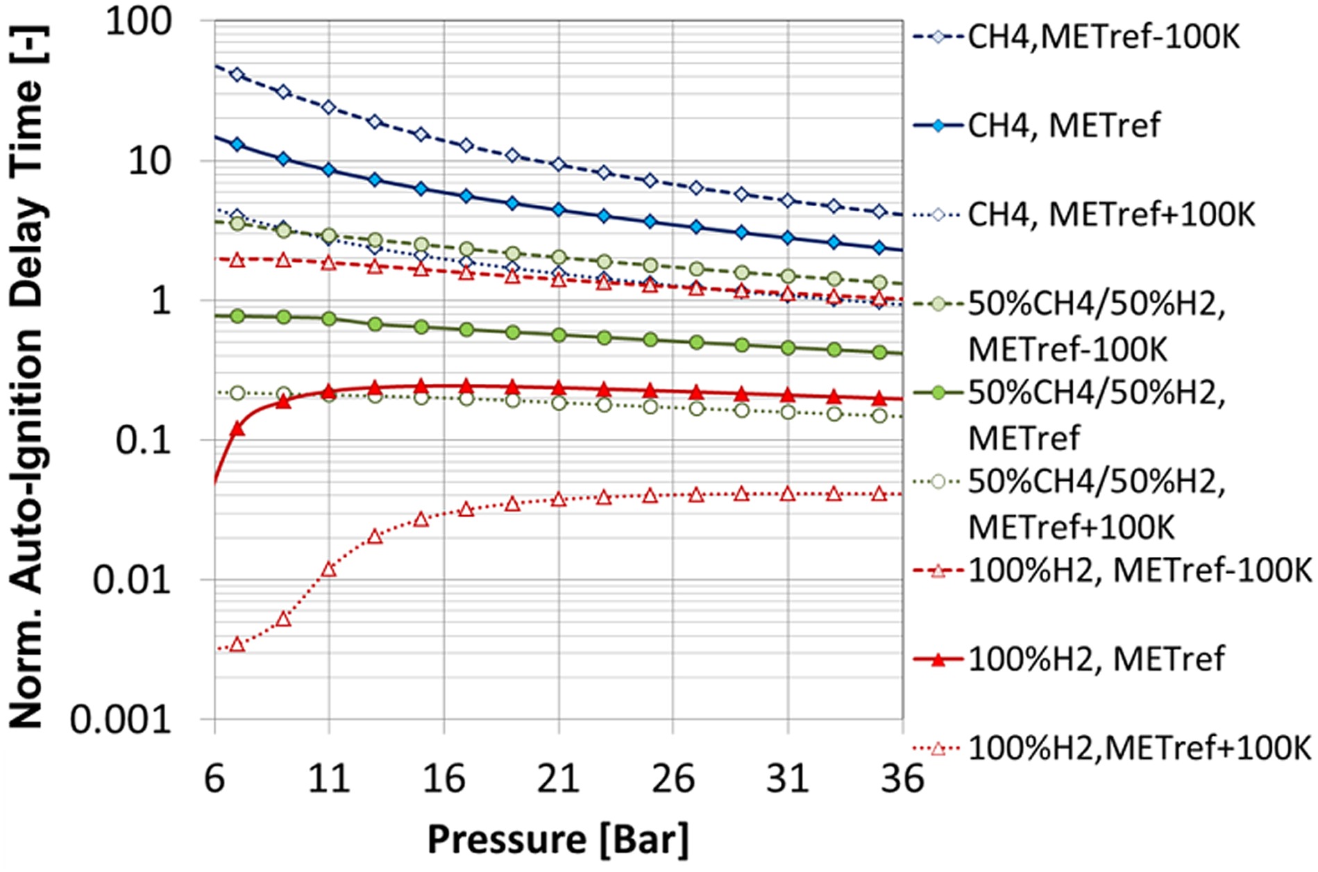
The influence of pressure on various fuel compositions has been thoroughly assessed to ensure robust burner operation over the entire engine relative load range. From Figure 3 it can be noted that for hydrocarbons, the auto-ignition delay time reduces with pressure; however, for fuels containing hydrogen, the trend is different. In particular, for elevated hydrogen contents, the auto-ignition delay time is lowest at lower pressures (<10 bar), corresponding to an engine relative load at which the second stage is not in operation. At higher loads (and pressures), the auto-ignition time increases again, becoming almost pressure independent beyond ∼16 bar.
MET dependence
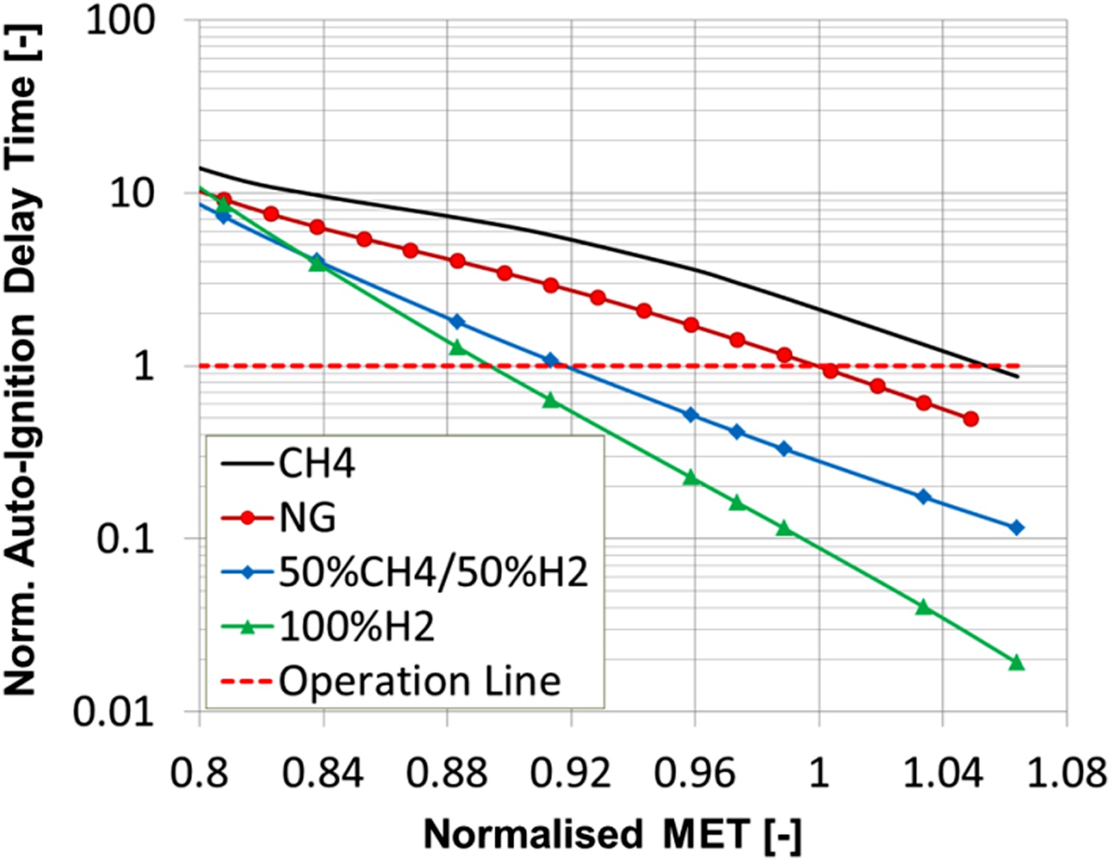
In sequential combustion, the position of the second stage flame is mainly driven by auto-ignition. To keep the flame outside of the burner mixing section, the auto-ignition delay time is used as a design parameter. In Figure 4, the design auto-ignition delay time is given as the operation line. The auto-ignition delay time varies for different fuels at given operating conditions. Pure methane is less reactive compared to fuels containing higher hydrocarbons, hydrogen, or methane/hydrogen blends. To compensate this difference in reactivity, the MET can be either increased or reduced to ensure operation at the target auto-ignition delay time as depicted by the operation line, so that the flame position can be held constant for a wide fuel reactivity range.
The MET control space for methane/hydrogen/higher hydrocarbon mixtures is shown in Figure 5. Fuels with high concentration of higher hydrocarbons and hydrogen can be robustly burned in the sequential combustion system at reduced MET.
Figure 5.
MET control space for varying hydrogen and higher hydrocarbon (C2+) fuel mixtures for the sequential burner operation line (optimum autoignition delay time).
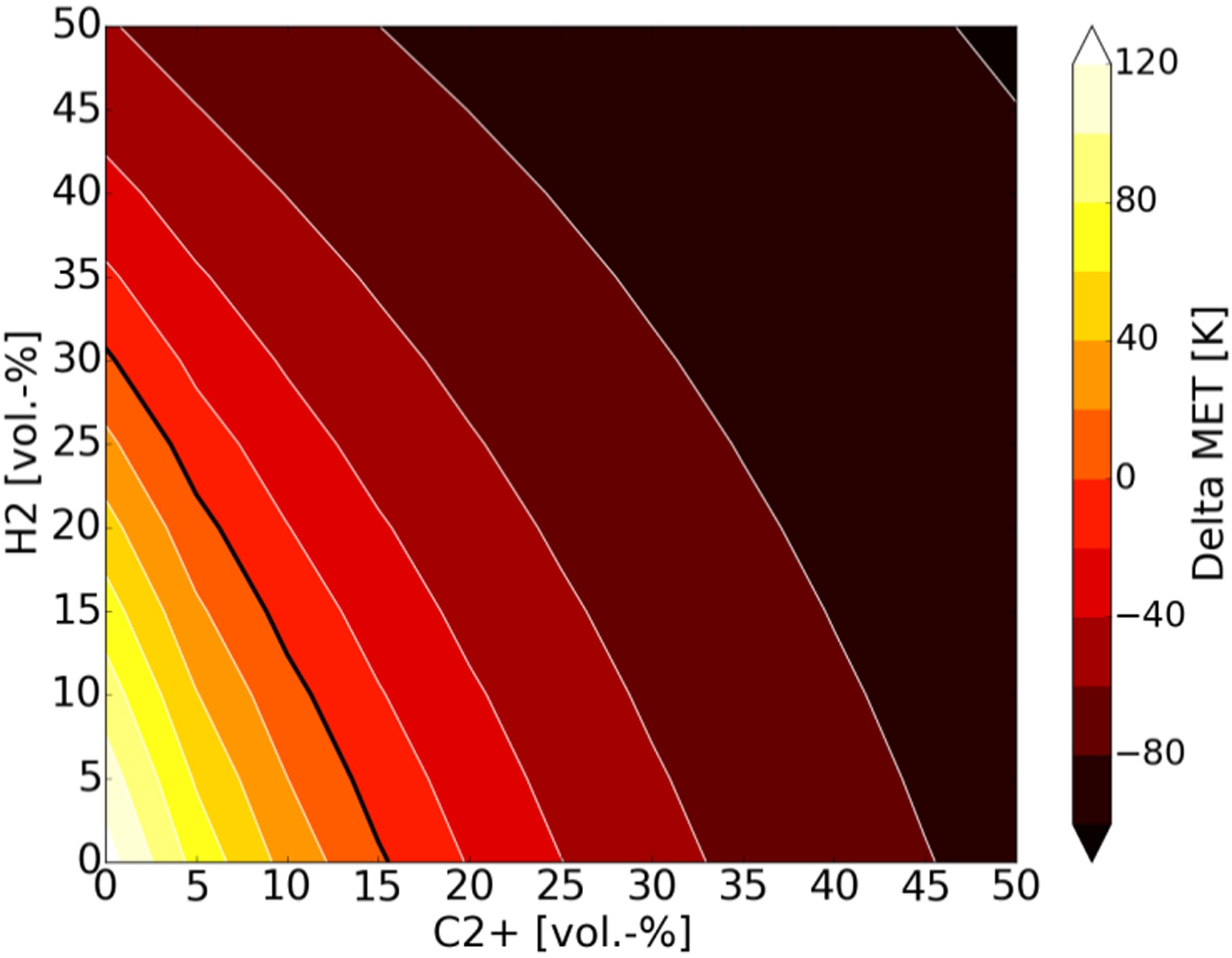
Alternatively, for low reactivity fuels (low concentrations of higher hydrocarbons and/or hydrogen) the MET is increased to maintain the target operational auto-ignition delay time (operation line).
A range of ±100 K from the nominal MET allows operation of the second stage with the entire methane/hydrogen fuel mixture range as depicted in Figure 5. For a given MET, the combustor exit temperature is maintained by adding or subtracting fuel to the second stage.
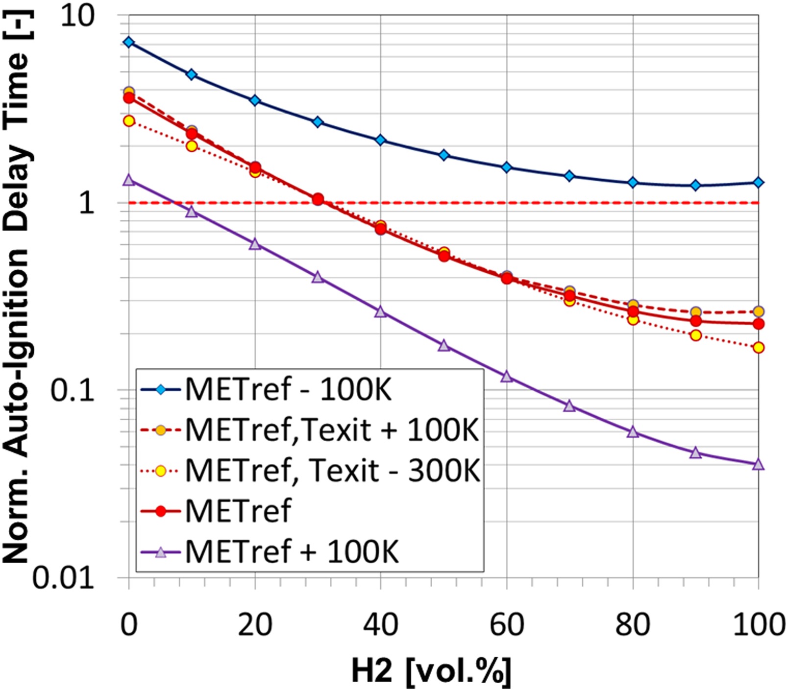
Figure 6 shows how the sensitivity of auto-ignition delay time to MET enables consistent burner operation for a wide range of fuel compositions. The horizontal dashed line shown in the figure represents the desired auto-ignition delay time, i.e. flame position, for optimal combustion performance, while the three solid lines represent the auto-ignition delay times at three MET levels. It can be seen from the figure that by adjusting the MET within this range it is possible to achieve the optimal auto-ignition delay time for the entire range of methane/hydrogen mixtures. The figure also indicates the insensitivity of the auto-ignition delay time to the flame temperature, represented by the red dashed curves, indicating that the combustor exit temperature, hence engine performance and efficiency, does not need to be adjusted to compensate a change in fuel reactivity.
Rapid mixing design
The use of inline injection combined with small scale mixing devices in the sequential burner (Pennell et al., 2017) allows the burner to operate on a wide range of fuel types without substantial change in the mixing quality. It has been shown that the mixing of an inline injector is largely independent from the momentum flux of the injected fuel (Poyyapakkam et al., 2012) and for this reason the performance of the burner, in terms of emissions, remains constant across a large range of fuel types and temperatures. By placing the mixing elements carefully in relation to the injectors it is possible to achieve rapid high quality mixing between the fuel and air. This optimisation of the placement of the mixing devices relative to the injectors means that the majority of the induced pressure drop is used to drive the mixing process; allowing high quality mixing for a moderate burner pressure drop. The careful design of the interaction between the induced vorticity field from these mixing elements and the fuel jet ensures mixing is maintained as the fuel type changes. The development of such a burner concept is considered in more detail in a previous paper (Poyyapakkam et al., 2012).
Analysis of the sequential burner has been performed using computational fluid dynamics for various fuel compositions and heating values (Table 1). The reacting flow was assessed with FLUENT 18.2 using Ansaldo Energia's reheat combustion model (Kulkarni et al., 2014, 2015) including further developments to predict propagation effects as suggested in (Kulkarni et al., 2017). The combustion model utilises a progress variable approach with tabulated chemistry derived from auto-ignition reactors and the “presumed pdf” method for turbulence-chemistry interaction. To model the turbulence, the realisable k-ε model is used (Shih et al., 1995). A representative two injector domain was modelled with an unstructured hybrid hexahedral mesh incorporating prism layers in the near wall region that was sufficiently refined to ensure accurate representation of the mixing process. The flow of vitiated oxidant into the burner is modelled with a velocity boundary while the fuel enters the domain by mass flow boundaries. The temperature of the oxidant stream (MET) is adjusted for the different fuel streams in the simulations in order to maintain the flame location.
Table 1.
Fuel compositions and heating values of assessed mixtures.
| Fuel composition [% vol] | Lower heating value [MJ/kmol] |
|---|---|
| Methane | 800 |
| Hydrogen/methane 50%/50% | 520 |
| Hydrogen | 240 |
| Hydrogen/nitrogen 85%/15% | 204 |
Figure 7, shows the evolution of the mixing along the length of the burner. It is shown that for the majority of the fuels studied, covering a range of heating values of almost a factor of 3.5, the impact on the mixing quality is negligible. Only for the lowest heating value fuel is the mixing significantly impacted by the fuel type.
Figure 7.
Progression of unmixedness along the SB for various fuel compositions, normalised by the unmixedness of the methane case at the exit of the burner.
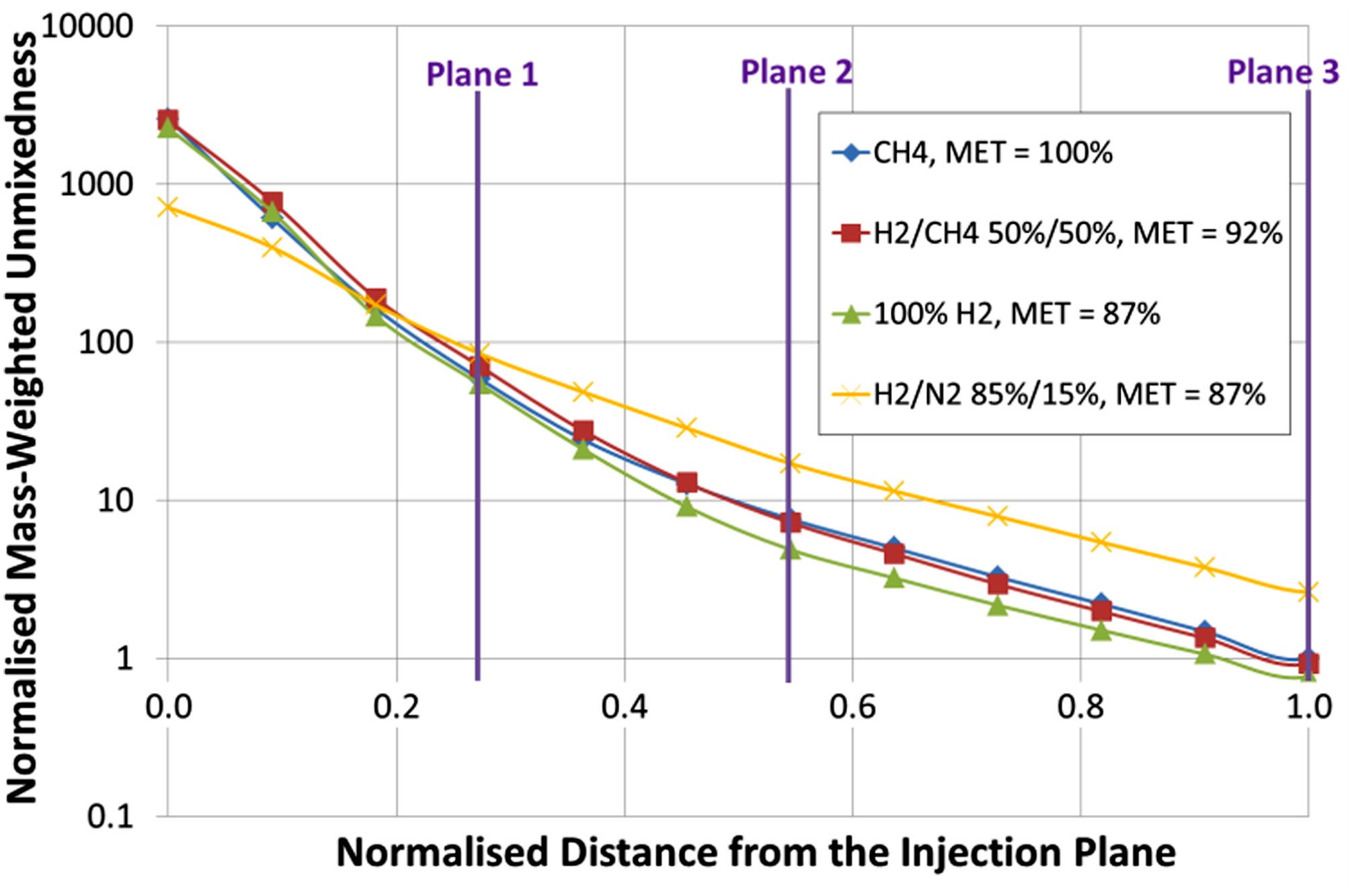
Figure 8 shows contour plots of the fuel mixture fraction at three axial locations within the mixing section of the burner (as indicated in Figure 7). The first column of contours are taken at a location close to the injectors and show the initial interaction of the fuel jet with the vortices introduced for mixing. The fuel is stretched laterally across the mixing channel, and this distribution is similar for all four fuel types.
Figure 8.
Contours of mixture fraction at three planes along the burner (Figure 7). Red shows fuel and blue oxidant.
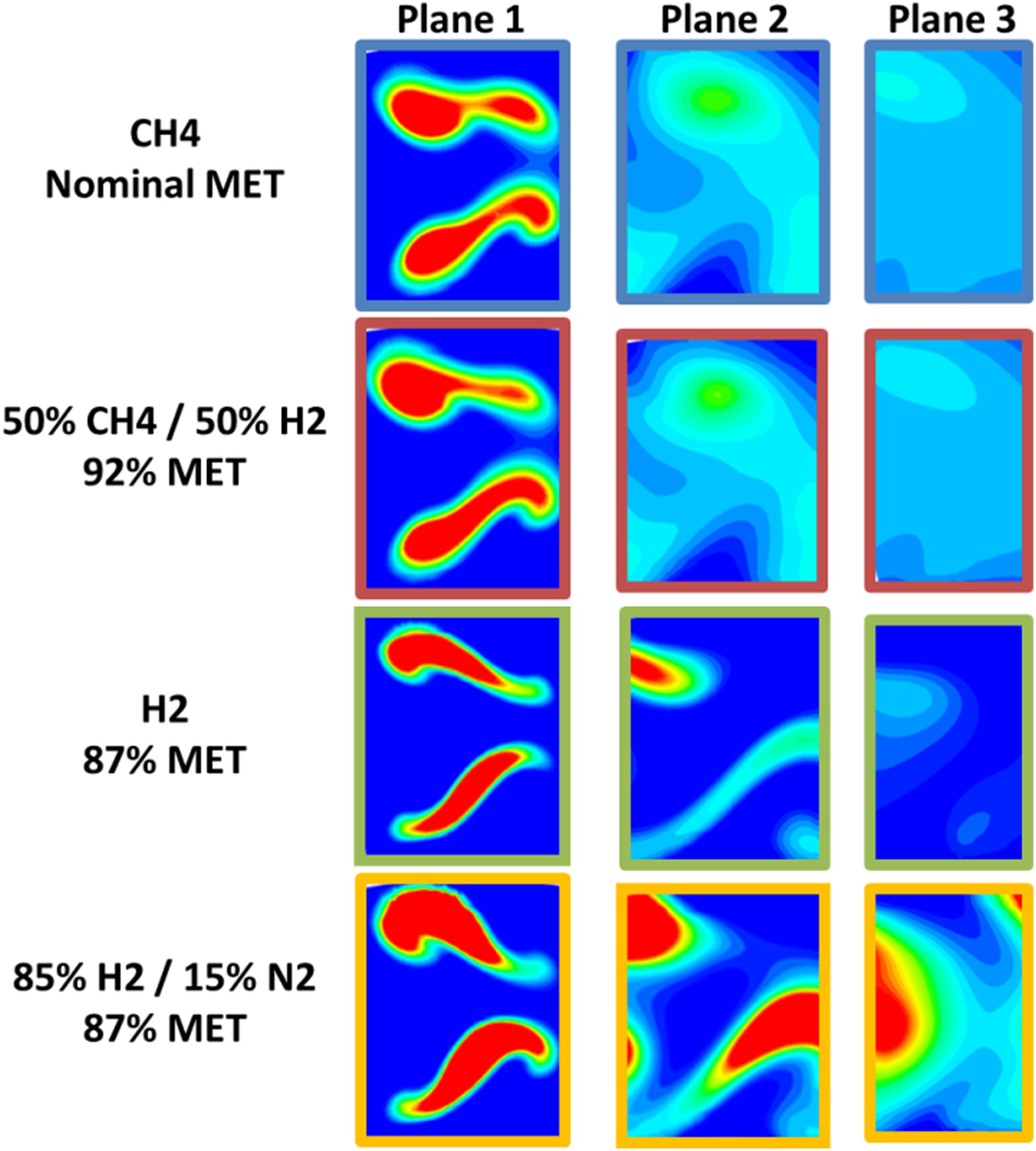
The second column of contours illustrated in Figure 8 is positioned towards the middle of the mixing section. These contours show that the fuel is already well distributed over a wide part of the channel. When going from methane to a 50% volumetric mixture of methane and hydrogen it is demonstrated that the mixing is not significantly impacted. However, for the other two fuels the mixing is more influenced, most notably for the hydrogen nitrogen mix.
The final column of contours shows the mixing near the exit of the mixing section. At this location, it can be seen, as expected from the previous discussion, that there is very limited difference for the methane and hydrogen/methane mix. Although differences can be seen for the pure hydrogen, it is, nonetheless, still well mixed and shows a distribution very similar to the other fuels. Again it is only the diluted hydrogen where the mixing can be seen to be significantly impacted.
Combustor validation at high pressure
High-pressure full-scale combustor tests, performed at the German Aerospace Center (DLR), Cologne, constitute one of the key validation steps in Ansaldo Energia's technology and product development. The tests reported here aimed at an extension of the flame position control by MET adjustment to a larger range of fuel reactivity. In particular, the practicality of operating a standard GT36 CPSC combustor with higher hydrogen content fuels and methane was validated. More information about measurements in the high pressure test rig can be found in (Pennell et al., 2017).
Operation with fuels containing hydrogen
When considering flame position control for application to fuels containing high hydrogen contents, it is fundamental to demonstrate the complementarity of the first and second stages on a quantitative basis, i.e. ensuring that the optimum inlet temperature of the second stage could match the operation concept of the first stage. For this purpose, the test campaign was structured into two parts as depicted in Figure 9:
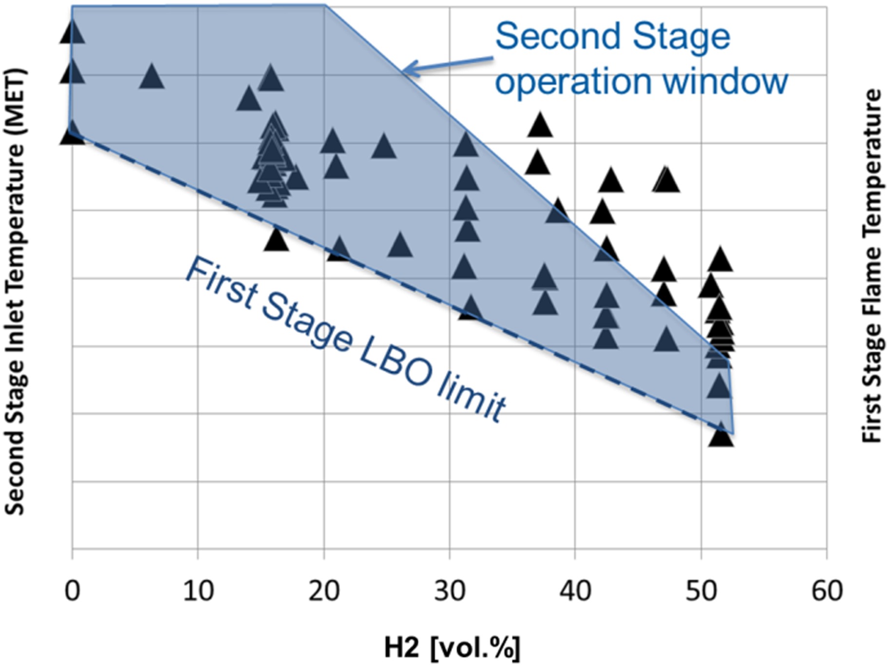
In the first part, only the first stage combustor was mapped keeping the second stage unignited. As expected, the first stage was proven to have a wide operation window, with increased hydrogen content extending the Lean Blow Out limit due to the increased fuel reactivity. This enables the targeted operation with a lower first stage temperature (black triangles).
In the second part of the testing, the combustor operation range was mapped including the sequential combustor (shaded area). During this testing it was demonstrated that the impact of the higher fuel reactivity on the sequential combustor can be fully compensated by derating the first stage. For all the illustrated mappings the exit temperature of the combustor was maintained constant.
The broad overlap between the first and second stage operation windows, confirmed the reaction kinetics predictions presented above, ensuring robust operation at engine level.
Figure 10 shows how key parameters, including hydrogen content, were changed during testing. The maximum burner metal temperature (red line) is used as monitoring parameter for flashback. While increasing the hydrogen content (green line), the MET was lowered (blue line) allowing the flashback margin to be maintained as indicated by the maximum metal temperature.

Operation with low fuel reactivity
The benefits of the CPSC combustion concept, in terms of fuel flexibility, have been presented in terms of chemical kinetics. This flexibility has primarily been considered in the context of more reactive fuels (i.e. high hydrogen content fuels) and validation of this flexibility has been presented in the previous section.
It is also clear from Figure 5, however, that the same CPSC flexibility can be applied when operating with lower reactivity fuel (i.e. methane). In this case fuel can be moved to first stage, increasing MET, to maintain the same flame position, ensuring unchanged combustion performance. This is particularly relevant to ensure sufficient residence time to fully burn out carbon monoxide at part load and to ensure similar thermoacoustic behaviour at base load.
This capability has also been validated during full-scale single burner tests at representative engine conditions both at base and part load. In Figures 11 and 12 the measured emission of NOx and carbon monoxide are shown normalised by their respective test limits. These test limits are set during single burner high pressure tests to ensure the engine guarantees will be achieved across the machine's entire lifetime. The data shown in Figures 11 and 12 compare the emissions measured during operation with methane (labelled 0% C2+ as it contains negligible higher hydrocarbon components) with emissions measured with the standard test fuel (labelled 7% C2+).
Figure 12.
NOx and CO emissions, part load operation, for fuels containing 0% & 7% C2+: the impact of the lower reactivity on emissions can be compensated by adjustment of the MET.
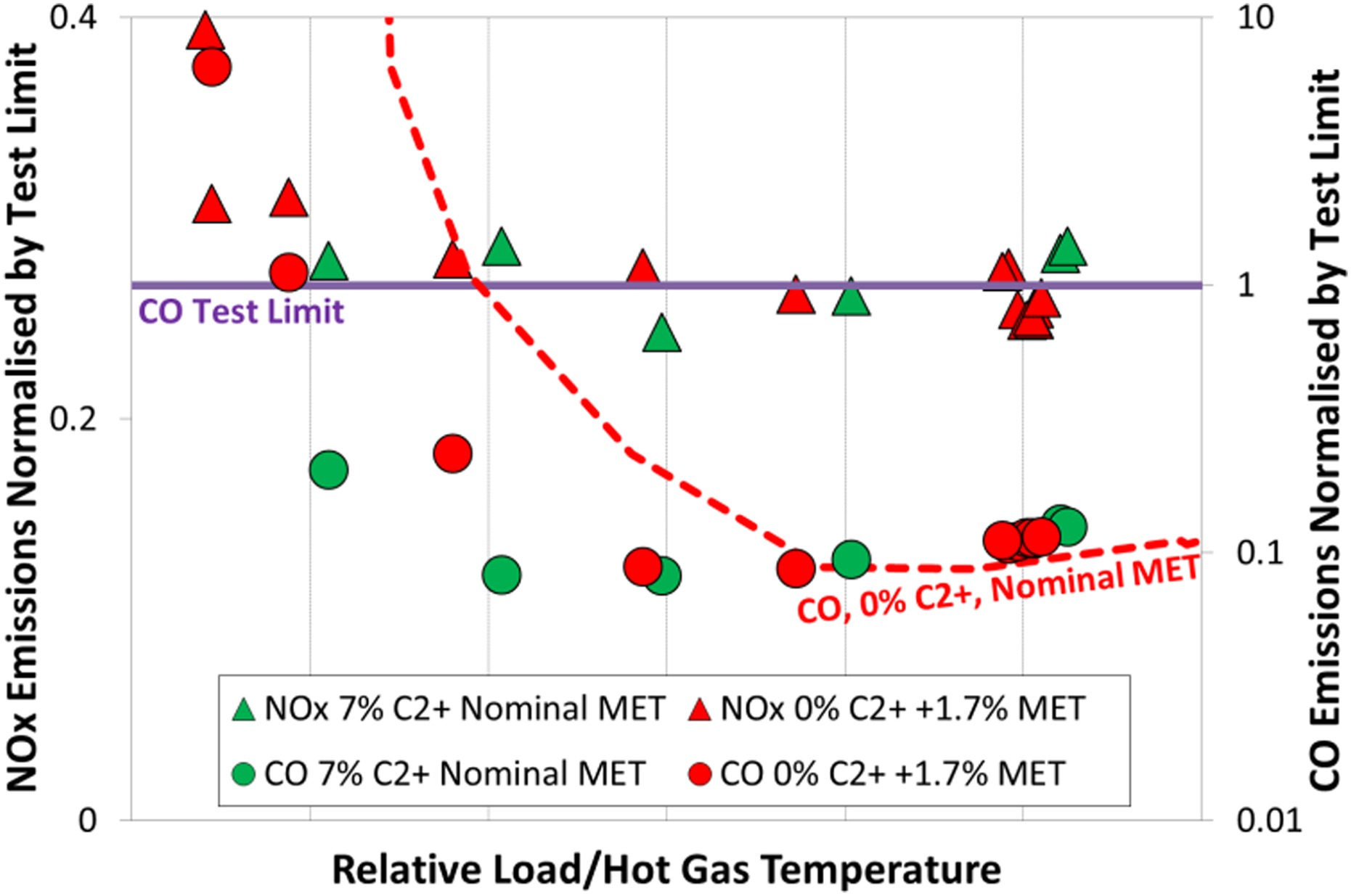
Figure 11.
NOx and CO emissions, base load operation, for fuels with 0% & 7% C2+: the impact of the lower reactivity on emissions can be compensated by adjustments of the MET.
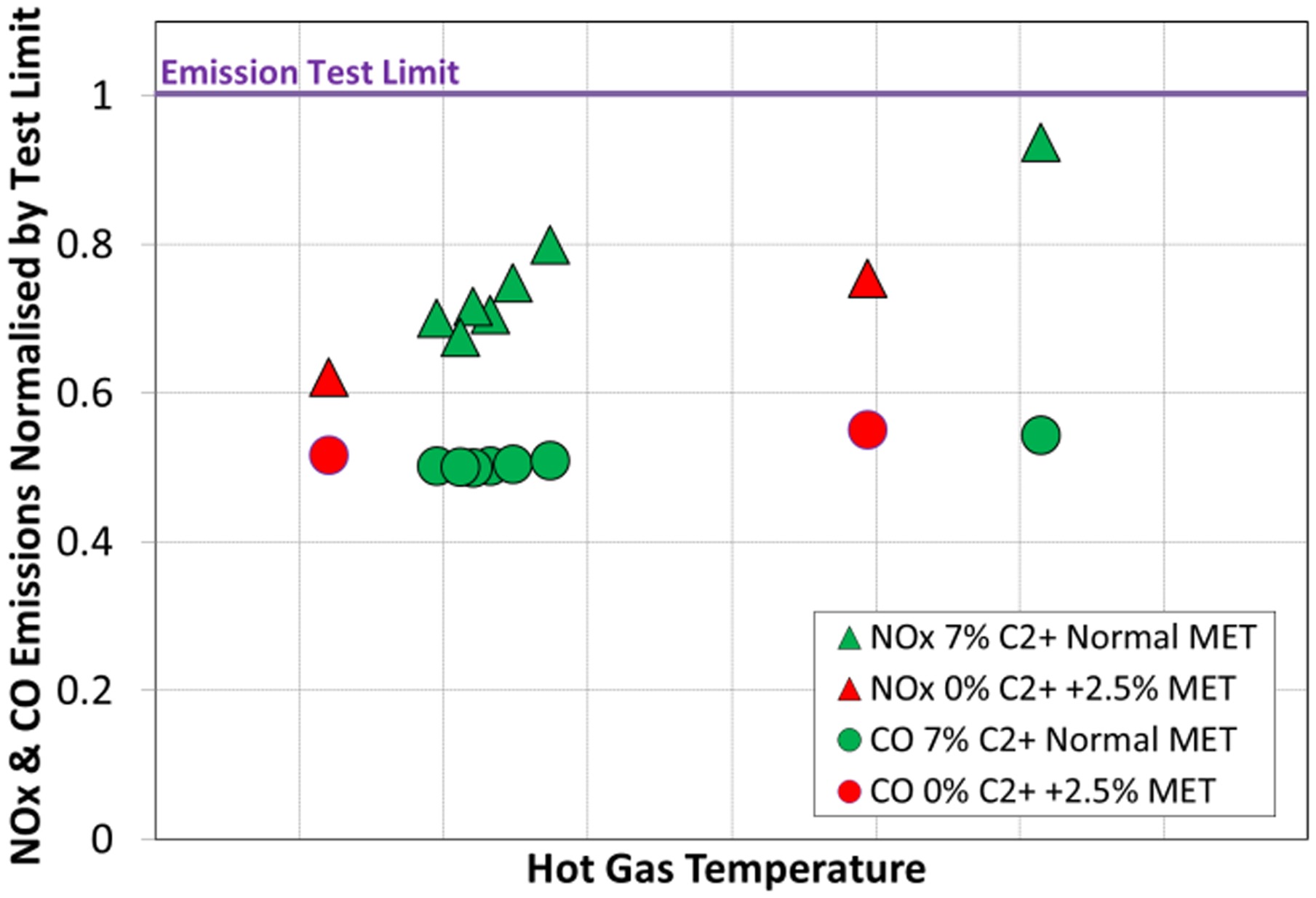
Figure 11 shows that the base load performance can be achieved with a moderate increase in MET. The specific challenge with a low reactivity fuel though is the ability to maintain the part load emissions of carbon monoxide.
Considering Figure 12, it can again be seen that a minor adjustment of the MET allows the same performance in terms of carbon monoxide to be achieved during part load operation. It is also shown that without this adjustment the turndown of the engine operating with methane would be compromised. Furthermore, it is shown that the required change in MET is not at the detriment of the NOx emissions.
Conclusions
Sequential combustion in gas turbines has an intrinsic advantage for fuel and operational flexibility: Ansaldo Energia's GT26 and GT36 engines benefit therefore from an additional tuning parameter: MET. This enables the adaption of engine operation to the widest fuel range and at the same time it minimises the penalty on engine performance due to combustion exit temperature derating, which is normally associated with less conventional fuels in low-emission premix combustion.
The fuel ratio between first and second stages is used to adjust the MET and therefore to optimise the flame location of both combustion stages. It has been demonstrated that this is an effective route to burn high volumetric blends of hydrogen with natural gas, at full combustor exit temperature. The high-pressure validation of the combustor fuel flexibility confirms the prediction from reaction kinetics and CFD calculations.
With the latest high pressure tests, the C2+ operation concept could therefore be extended to high hydrogen fuels. This allows the GT36 to be operated all the way from pure methane up to 50% volumetric hydrogen content with stable combustion on all stages without any modification of the standard hardware.
Based on this result, a further increase in hydrogen content is envisaged in the short term future (Bothien et al., 2019) and 100% hydrogen operation is considered feasible.
Nomenclature
CPSC
Constant Pressure Sequential Combustion
CO
Carbon Monoxide
C2+
Hydrocarbons with at least two carbon atoms
EV
EnVironmental (GT26 First Stage)
FS
First Stage
HP
High Pressure
LBO
Lean Blow Out
MET
Mixer Exit Temperature = Second Stage inlet temperature
NOx
Oxides of Nitrogen
SB
Sequential Burner/Second Stage
SEV
Sequential EnVirnomental (GT26 Second Stage)