
Introduction
Shortened civil aero engine intakes could lead to fuel burn savings by reducing the weight and drag of the nacelle (Hoheisel, 1997). This effect is especially important given the ongoing trend towards lower pressure ratio, larger engine fans which increase the nacelle diameter required for a given engine thrust. However, short intakes deliver a more distorted flow to the fan, which can influence its performance especially at off-design conditions.
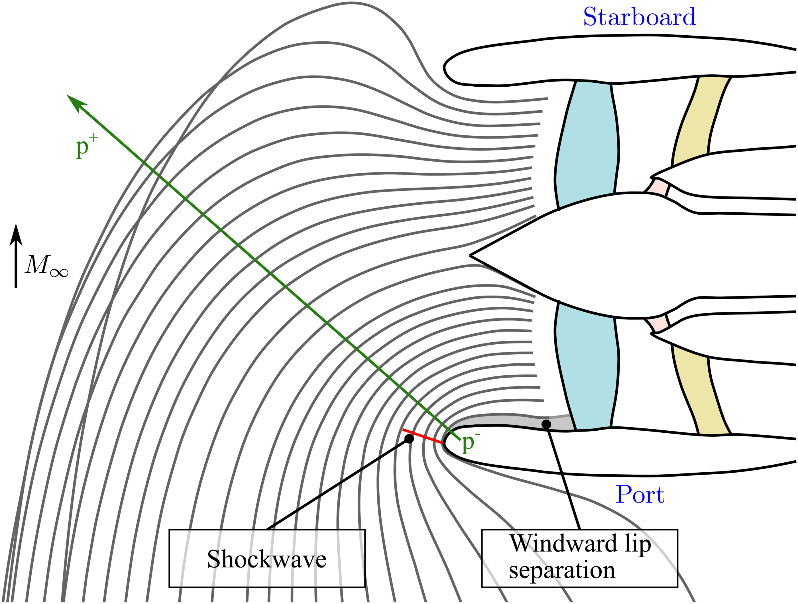
Crosswind is here defined as the operating condition where the freestream vector is parallel to the ground plane and normal to the engine axis. Figure 1 presents a sketch showing a section of the fan and intake system for a plane parallel to the ground that passes through the engine centreline. The figure shows ingested streamlines that pass through this plane just upstream of the fan for a strong crosswind from the right. This operating condition is characterised by the following features:
The captured streamtube area far upstream of the engine,
As the intake aligns the captured streamtube with the engine, a region of high streamline curvature appears near the intake windward leading edge. The curvature diminishes with distance from the leading edge, resulting in the static pressure gradient shown in Figure 1.
At high mass flow conditions, the streamline curvature around the windward lip creates a patch of supersonic flow, which can terminate in a shockwave and separate the boundary layer.
The intake diffuser imposes an adverse pressure gradient downstream of the intake throat. This gradient can separate the boundary layer from the windward lip or act to prevent reattachment if the boundary layer has already been separated upstream by a shock.
A short intake cannot fully turn and align a strong crosswind with the engine centreline, leading to angular distortion at the fan face.
Figure 1.
Top view of engine section symmetry plane and ingested streamlines for crosswind from the right.
For a given fan rotational direction, the ground vortex can be either co-rotating or counter-rotating relative to the fan. The sense of rotation of the ground vortex is determined by the crosswind direction. The ingestion of a counter-rotating ground vortex has been linked to increased fan pressure ratio and reduced isentropic efficiency, whilst the opposite trend holds for a co-rotating vortex (Castillo Pardo et al., 2014). The interaction of the fan with tip-low total pressure distortion has been found to rise the work and pressure rise (Allen et al., 2021). However, both studies prescribed the distortion and no upstream effect of the fan on the distortion generation was accounted for.
The remainder of this paper is structured as follows. We first introduce the fully coupled numerical model of the low pressure compressor system of the prototype UHBPR turbofan. We then describe the different test cases that are used, focusing on two different intake designs and both crosswind directions. The resulting intake flow field is then analysed in detail, emphasising the interaction between the nacelle separation, ground vortex ingestion and the resulting distortion present at the fan face. We then consider the fan stage flow field for all cases, showing that the fan response changes significantly for left and right crosswind and for each intake design. Finally, the implications of crosswind operation on overall performance and loss are quantified for each part of the low pressure compressor system.
Test cases
Figure 2 presents a schematic of the numerical domain used for the coupled crosswind simulations. The fan and installation system comprises: (i) a conventional intake with
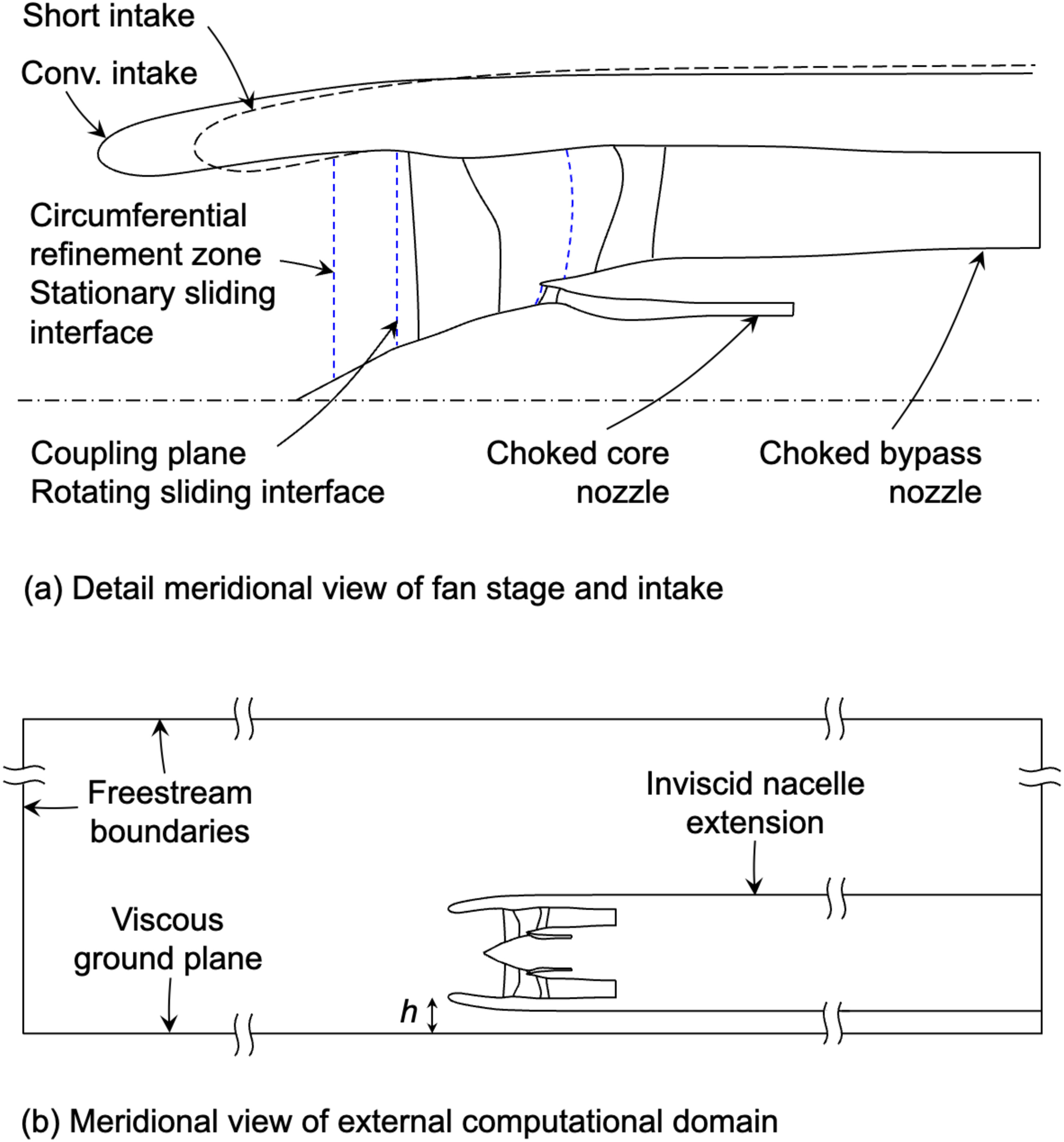
Table 1.
Fan and intake design parameters.
Table 2 presents a summary of the main crosswind operating conditions studied in this paper. Two different crosswind angles are analysed:
Computational methods
Full annulus, unsteady simulations were carried out using the GPU-accelerated Reynolds-averaged Navier Stokes solver Turbostream (Brandvik and Pullan, 2011). Boundary layers were modelled as fully turbulent and the one-equation Spalart-Allmaras (SA) turbulence model (Spalart and Allmaras, 1992) was used for all simulations along with adaptive wall functions on all solid walls. The helicity-corrected version of the SA model (Liu et al., 2011) was applied, based on previous work showing its suitability for predicting separated and stalled flows in fans (Lee et al., 2018; Kim et al., 2019). Jameson’s dual time stepping method (Jameson, 1991) was used to march the simulation in time with 2880 time steps per revolution. This temporal resolution has been used and validated successfully in Turbostream for the prediction of stall inception in low pressure ratio fans (Kim et al., 2019).
The boundary conditions are defined at sea level conditions, representative of a beginning of runway condition. Freestream static properties
Within the fan stage, a long converging choked nozzle is used to set the core exit boundary condition. The area of the core nozzle is adjusted to obtain the mass flow at the reference operating condition, and it is later held constant for crosswind, fixing the non-dimensional outlet core mass flow. A converging choked nozzle is also used to set the bypass exit boundary condition. The bypass nozzle area for the simulations was determined by first running a single-passage, steady characteristic where the bypass nozzle area was varied to control the fan operating point. This characteristic intersects the sea level static fan working line at a particular nozzle area. This area was then applied to the simulations. This mimics the behaviour of a choked engine nozzle. When crosswind is introduced, the fan performance changes compared to the design point and its operating point moves along an operating line defined by a constant non-dimensional exit flow function. In reality, the nozzle of a low pressure ratio fan at a sea level static condition is likely to be unchoked. In this case, the fan operating point would move along a different operating line to that shown here, determined by the nozzle geometry and far field static pressure. This line would have a lower slope and bring the fan closer to its stability limit. The larger the deviation from the design point, the larger the difference between choked and unchoked conditions. The results shown here represent small excursions from the design condition, despite the large distortion, so this behaviour would not affect the findings shown. The unchoking behaviour of a real nozzle could be modelled by including the rear nacelle and exhaust geometry directly in the simulation.
Multi-block structured grids were generated for the fan stage and intake domains using NUMECA Autogrid (NUMECA International, 2016) and Pointwise (Pointwise Inc, 2023), respectively. A
A mesh independence study of the external domain was performed with the procedure proposed by Celik et al. (2008). An isolated engine installation subjected to 35 kt of crosswind was assumed, with uniform and constant pressure boundary condition at the fan face. Three levels of mesh refinement were studied: level 1, 2 and 3. These correspond to
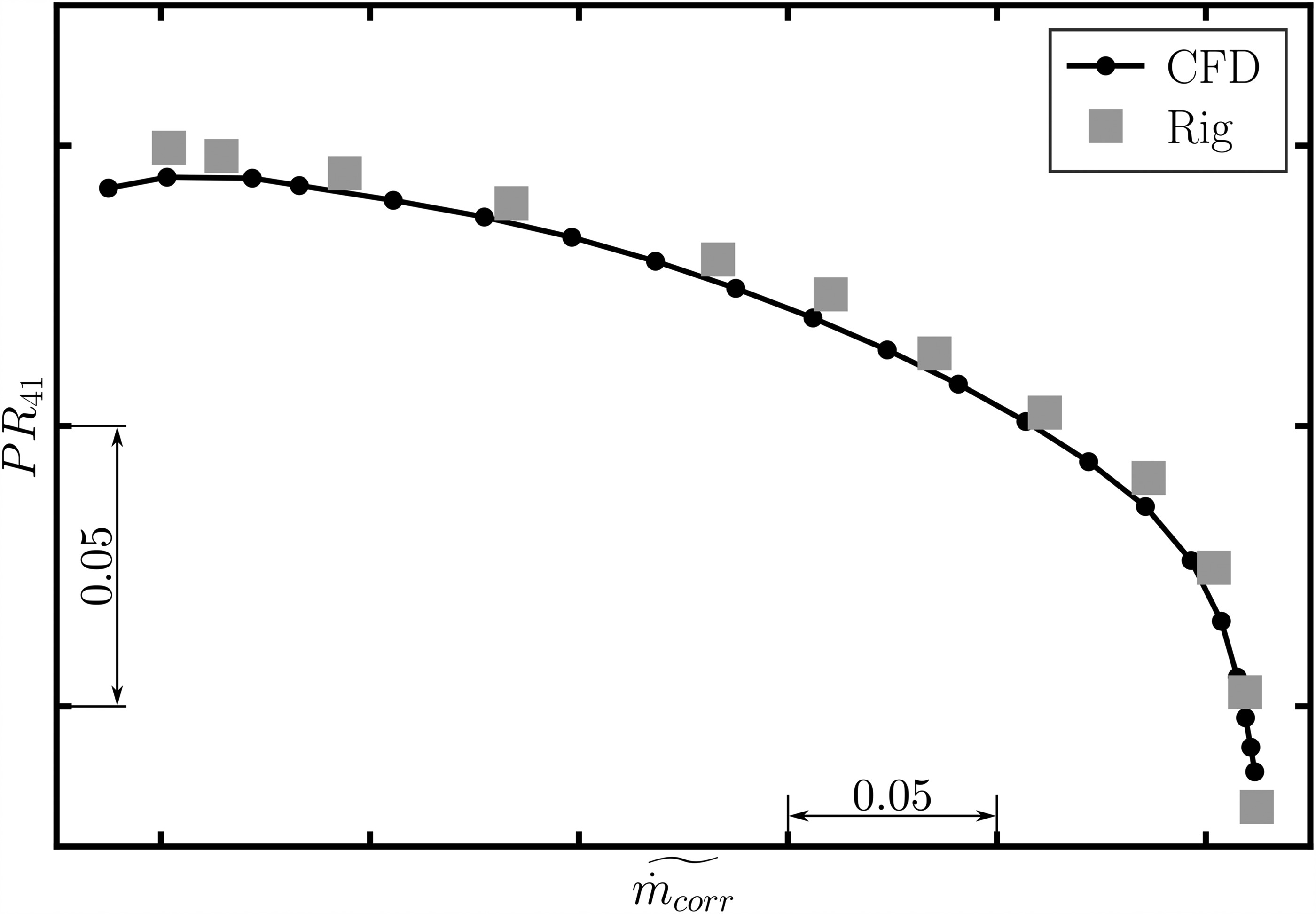
A subscale version of a similar transonic fan stage was experimentally tested to validate the numerical model. Single-passage steady-state simulations of an isolated fan stage were performed for this validation. The simplified domain comprises a fan blade connected to a long straight intake duct and axisymmetric ESS and OGV vanes attached to their respective choked long nozzles. Figure 3 shows close agreement between numerical predictions and rig measurements of the design speedline.
Intake flow field
The flow under crosswind has two additional complicating factors compared with regular operation. Firstly, the intake droop plane is normal to the direction of the freestream flow. Secondly, the intake and fan are influenced by the presence of the ground, which modifies the potential field and leads to ingestion of a ground vortex. Some of the resulting effects are sketched in Figure 4.
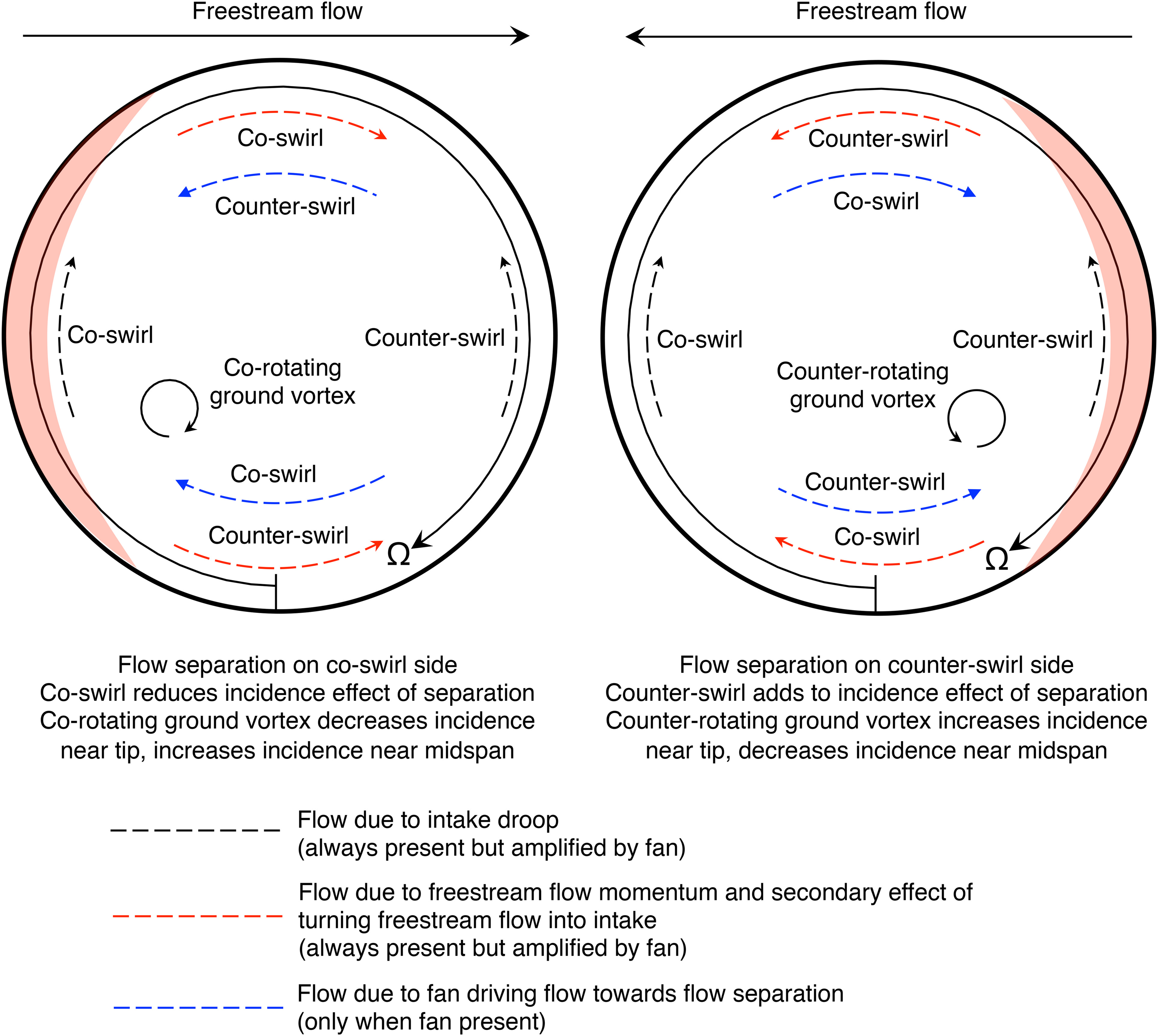
The droop and freestream flow directions are orthogonal, creating two secondary flow components. The centripetal pressure gradient created as the flow is turned into the intake leads to low static pressure and a mass flow increase on the windward side. As the flow returns to a more uniform mass flow distribution, it migrates downwind across the annulus. The fan amplifies this effect. However, this effect acts in opposition to the fan’s tendency to drive flow towards the separated area on the upwind side. This is shown by the opposing blue and red arrows. The intake droop also creates a tendency for flow to migrate upwards, generating a different secondary flow component under crosswind.
Both of these flow features can create co-swirl and counter-swirl in different locations relative to the intake flow separation depending on the freestream and fan rotational directions. The potential for different freestream and fan rotational directions also creates two possible senses of rotation of the ground vortex relative to the fan. The fan response to crosswind is therefore highly asymmetrical. The results presented here are shown with the fan rotating clockwise in all cases and the freestream flow is either from the left or right, as shown in Figure 4. These effects also lead to spanwise flows, which have been shown to be important at high angle of attack operating conditions (Mohankumar et al., 2021). In the present work, the freestream component of momentum is lower and the dominant effects were found to be explained by the way that these flow features superimpose to create non-uniform inlet axial velocity and swirl patterns.
Prior to running the simulations it is not obvious how these effects will combine or what the final flow field will look like. It will depend on the detailed balance of the freestream flow speed, intake design and fan design. This creates an additional reliance on the CFD to make the right prediction and is likely to complicate the challenge of designing the system for this flow field.
Figure 5 shows top-down views of the time-averaged intake flow field under crosswind. Figure 6 shows corresponding fan inlet axial mass flux distributions. The streamlines show that the fan captures flow from well round the outside of the engine cowl. This leads to higher streamline curvature and acceleration around the upwind lip compared with other flight conditions such as high angle of attack operation. In all 4 high mass flow cases considered here, a shock wave sits on the highlight around the upwind side of the intake, which separates the boundary layer immediately downstream.
Figure 5.
Contours of time-averaged Mach number and streamlines on a cut through the thickest part of the intake flow separation for coupled fan-intake operation under crosswind.
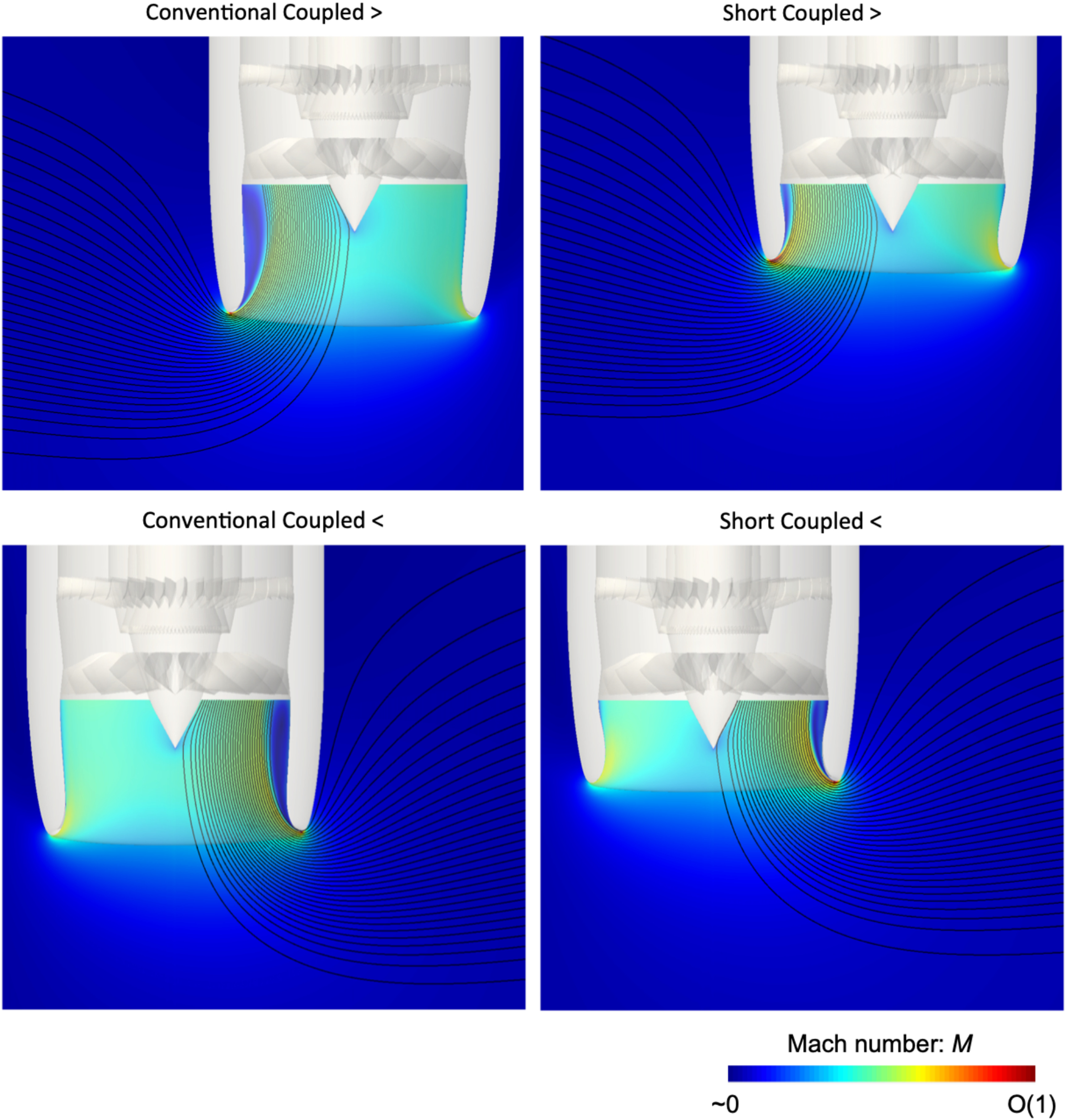
Figure 6.
Contours of axial mass flux at fan inlet for coupled unsteady calculations under crosswind.

For both conventional and short intakes, and both freestream directions, the overall streamline pattern and initial location of the separation is similar. However, the downstream development of the separation differs because of the change in proximity to the fan pressure field with intake length and due to the relationship between the separation, potential field and fan rotation.
In the conventional intake, the separation grows to a larger spanwise height than that in the short intake, but the fan causes reattachment before the flow reaches the leading edge. This is shown by positive axial mass flux in Figure 6. The influence of the fan means the separation stays at a smaller size in the short intake, but the steeper diffuser angle prevents full reattachment. There is still reversed axial flow just upstream of the fan.
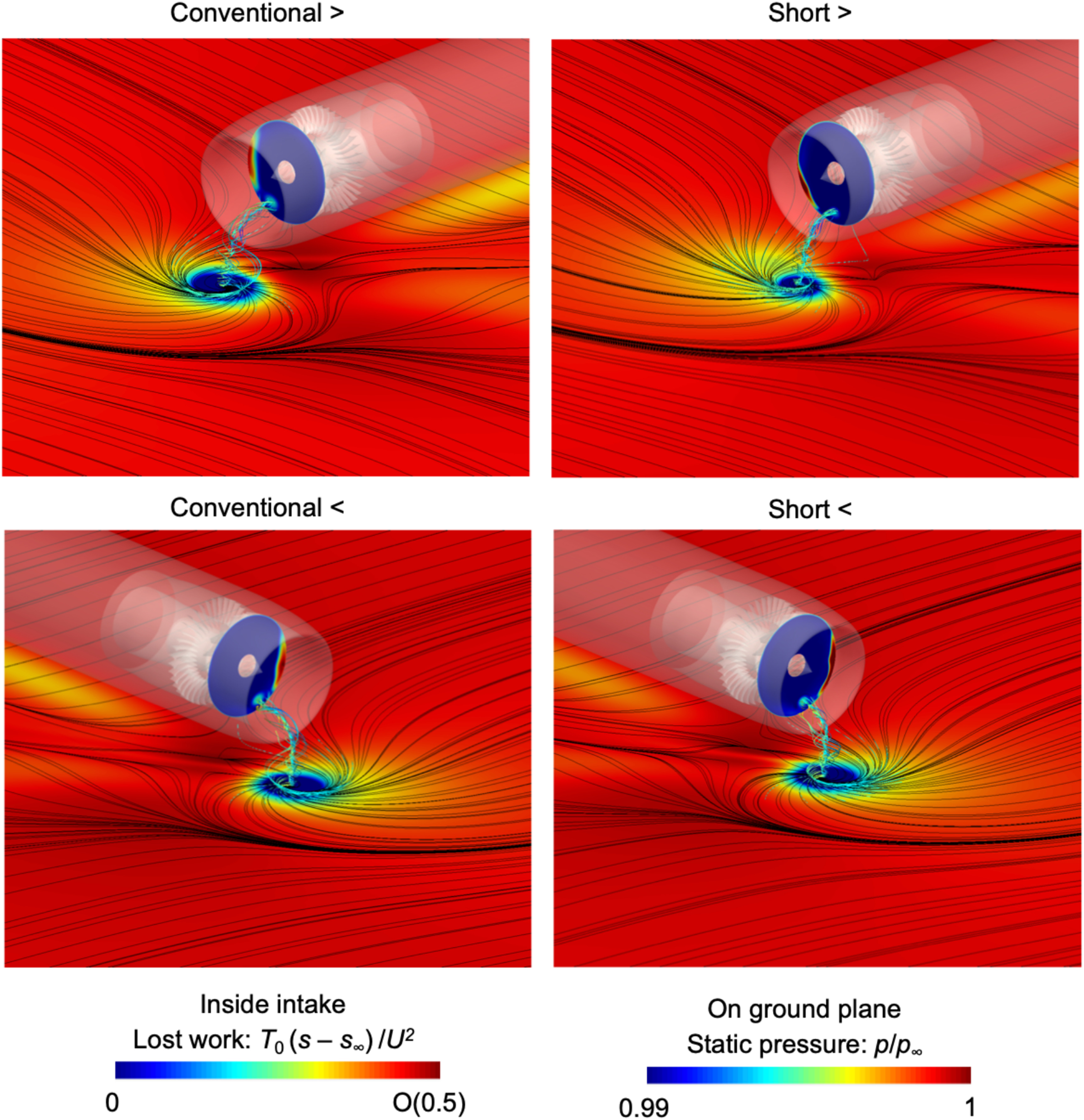
The ground vortex appears as a region of slightly reduced mass flux, but it is not as low as the intake separation. Figure 7 shows that the origin of the ground vortex is similar for both flow directions and both intakes. This can be explained by the fact that the separation point on the ground is relatively far away from the fan in all cases, of the order of one fan diameter. The separation is therefore driven by the bulk suction from the engine, which at this distance will be determined mainly by the 1D fan operating point alone rather than the detailed fan flow field. These results suggest the origin of the ground vortex is relatively unaffected by flow direction and intake length. Previous findings on the ground vortex in the literature should be equally applicable to short intake designs. In particular it will be shown below that the direction of the vortex is important for the fan performance.
Fan inlet flow field
Figures 8 and 9 show the time-averaged fan inlet Mach number and swirl angle distributions. Figure 10 shows the resulting fan inlet incidence for the crosswind cases relative to operation in clean flow on the working line at the same fan speed. The dominant long length scale effect is for a general trend of high Mach number on the upwind side of annulus relative to the downwind side. This is exacerbated by acceleration around the blocked area of the flow separation. There is an additional, but smaller, trend of high Mach number at the bottom of the annulus due to the droop.
Figure 8.
Contours of time-averaged Mach number at fan inlet for coupled unsteady calculations under crosswind.
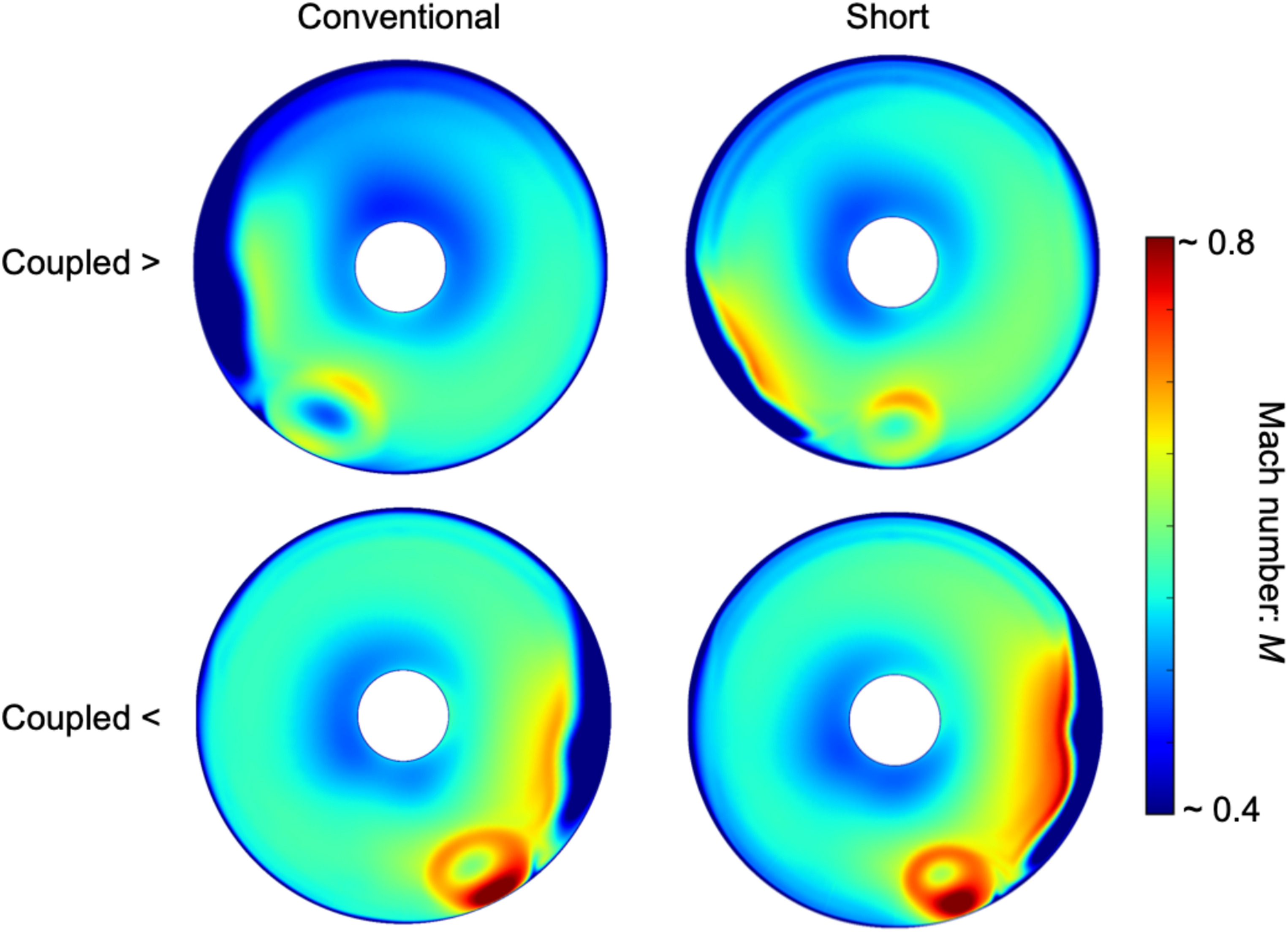
Figure 9.
Contours of time-averaged absolute swirl angle at fan inlet for coupled unsteady calculations under crosswind.
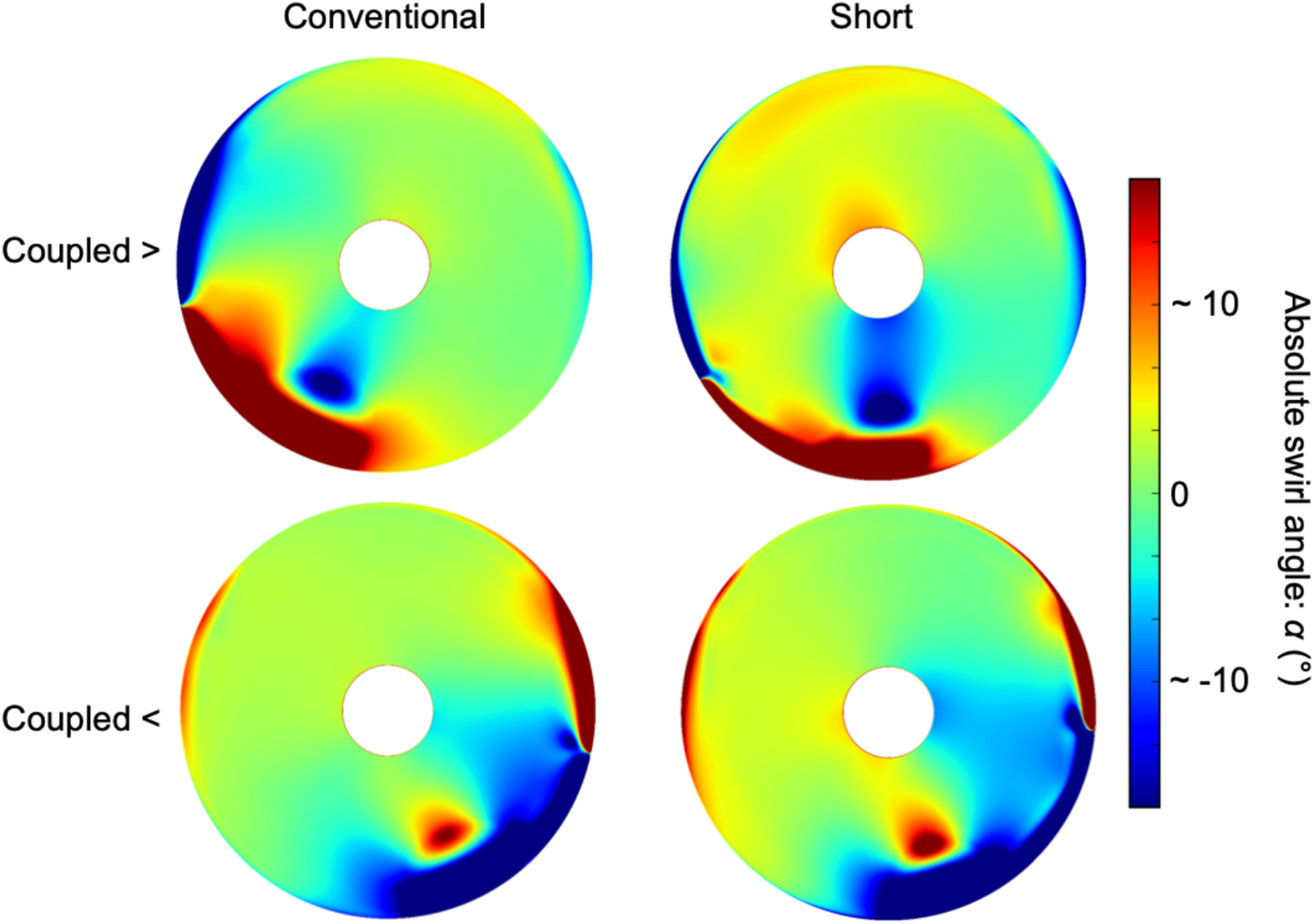
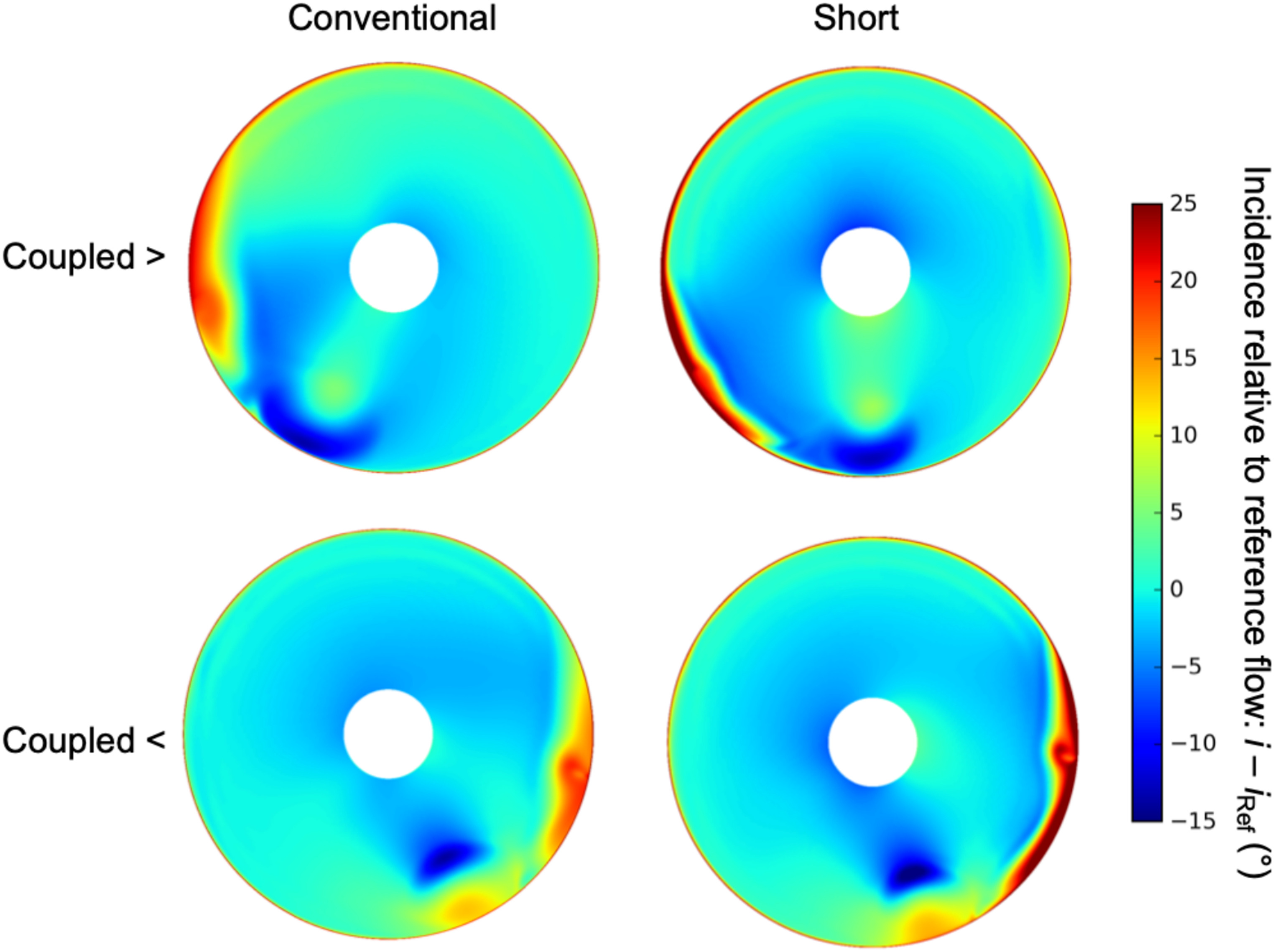
Figure 10.
Contours of incidence at fan inlet relative to clean fan-alone flow field for coupled unsteady calculations under crosswind.
Below the separations there are large regions of strong co-swirl or counter-swirl at the casing. The flow direction in these regions is against the freestream direction. They are primarily caused by the local rotation of the ground vortex, which tends to be ingested near the upwind separation location. This effect occurs with a similar intensity in both intake lengths, consistent with the fact that even in a short intake, the fan is relatively far removed from the source of the ground vortex so does not influence its creation or angular momentum. These casing swirl regions are also partly caused by the redistribution of flow towards the separated area. This can be seen by the presence of opposing, but significantly smaller, mirrored regions above the separation.
At around midspan the ground vortex rotation creates a region of swirl in the opposite sense to that above. This is a smaller length scale effect than the bulk flow distortion but still affects the flow over the full blade height and a width of several blade passages.
When the separation is on the right side of the annulus, it coincides with counter-swirl created by the droop (discussed below). It also coincides with an area of counter- swirl from the ground vortex. All three effects tend to increase the fan suction. For a left side separation, the suction effect imparted to the separation is moderated by co- swirl from the droop and ground vortex. The upstream acceleration effect is therefore stronger for a right-side separation than a left-side one, so the strength of the fan coupling effect depends on the freestream flow direction.
An additional, longer length scale component of swirl affects the flow away from the separation and ground vortex. The flow in the bottom half of the annulus is dominated by the ground vortex, so this additional effect is only noticeable in the upper half.
As a rough guideline, the long length scale swirl effect leads to co-swirl in the upper annulus half for freestream flow from the left and vice-versa. Independently of the freestream direction, the droop creates counter-swirl on the right side and co-swirl on the left side. However, the effects are asymmetrical under a change in freestream direction. They are driven by the balance between opposing effects in Figure 4 and altered by the response from the fan and location of the separation.
The above effects are all reflected in the fan inlet incidence distributions in Figure 10. These plots show a peak-to-peak incidence fluctuation of
The combination of the ground vortex, separation and 3D intake shape creates complex 3D flow distributions near the casing. Note the large incidence variations at around 85% span. These are due to the additional secondary flow components in Figure 4 combined with the ground vortex. The superposition gives different results for the different freestream directions. The combination of counter-swirl from the ground vortex and low axial velocity from the separation gives very high relative Mach number and incidence near the casing for flow from the right. For flow from the left, the combination is such that the flow is only just supersonic. This helps to explain why flow from the right leads to significantly higher fan loss, as will be shown below.
Fan stage flow field
Figures 11 and 12 show the instantaneous and time-averaged rotor and stator exit flow fields respectively. In all cases the intake flow separation creates further flow separations around the tip of the rotor blades immediately downstream. The details change depending on both intake length and freestream flow direction and the discussion below is divided by direction.
Flow from the left
For a left-side separation the main set of rotor tip separations is larger in the conventional intake. This is despite the fact that the flow reattaches before reaching the fan for the conventional intake, but remains separated in the short intake. One of the key reasons for this is that the short intake leads to stronger co-swirl in the upper half of the annulus (Figure 9). This creates a region of negative incidence (Figure 10), reducing the turning required in the rotor immediately after it leaves the separated region. The rotor blade flow is quickly “cleaned up” and reattached after leaving the intake separation, in contrast to the conventional intake where separations persist around the upper annulus.
The intake separation in the conventional intake also occupies a larger fraction of the blade height, causing large corner separations in the rotor. In the short intake the rotor flow does not form full corner separations. Instead there are distinct patterns of separated casing flow (which in fact is the intake separation itself convecting through the rotor, not a new separation in the rotor) and smaller, two-dimensional separations further down the rotor span.
For flow from the left, the ground vortex is distinct from the intake flow separation so its effect on the fan can be seen clearly. It creates counter-swirl around midspan, leading to an isolated separation on one rotor blade. The flow quickly reattaches as the blade leaves the vortex. This is a very small effect compared with the effects from the intake separation and potential field influences on the flow. This is partly due to the short length scale of the ground vortex and partly because it is acting to reduce the tip incidence, which somewhat alleviates the effect of the blades entering the intake separation. It is better for the ground vortex to raise the incidence near midspan where the blades are otherwise unaffected.
For flow from the left onto the conventional intake, the fan inlet flow field and loss were found to vary unsteadily. Of the four cases tested, this was the only one where significant unsteadiness occurred. It will be shown below that this case has the highest average fan loss so it is possible that this case is brought closest to stall and the unsteady fan-intake interaction is indicative of an almost-stalling behavior, which has been observed in real engine tests (Freeman and Rowe, 1999).
Referring to Figure 12 the OGV is affected by further flow separations near the casing, downstream of the corresponding separations in the rotor. An additional area is affected by the upstream ground vortex. Wherever the ground vortex is co-swirling the rotor work input is reduced, lowering the OGV inlet stagnation pressure. The resulting low energy flow separates in a group of blades downstream of the vortex. This effect is similar in both intakes. The ESS is relatively unaffected for this freestream flow direction, as the rotor loss and ground vortex influences tend to remain confined to the casing, but does experience regions of increased corner separation size which lie downstream of enlarged rotor hub corner separations (Figure 11).
Flow from the right
For flow from the right, the ground vortex acts to increase the tip incidence and is located near the intake separation. Its effect merges with that of the separation, making the rotor flow separations larger and tending to form corner separations extending down the span.
In this case it is the short intake that leads to larger flow separations in the fan, although the difference between the two intakes is smaller than it was for a left-side separation. Figures 9 and 10 show that outside the separation, the short intake has stronger counter-swirl and greater positive incidence in this region. This increases the loading elsewhere on the blade, allowing the separations to grow larger.
This is essentially the opposite of the beneficial co-swirl effect created by the short intake for freestream flow from the left. This observation helps to explain the performance results in the next section, where the short intake leads to better fan rotor performance than the conventional intake for flow from the left, but worse performance for flow from the right.
The impact on the OGV (Figure 12) is also more severe for this freestream direction and this is largely a secondary consequence of the increased rotor loss. A large group of separations is present at the bottom of the annulus for both intakes, immediately downstream of the large rotor tip separations. Again, for this flow direction the ground vortex influence on the loss merges with the influence of the intake separation so the OGV separations are grouped into one area instead of being split. The ESS is affected in the same way due to the presence of large rotor hub corner separations (Figure 11).
Performance
Figures 13 to 15 break down the overall effect on stage performance. Pressure ratio and mass flow rate are reduced compared to their clean-flow values on the working line. However, the mass flow rate remains well above the stalling value. The finding is that there is a steady reduction in thrust rather than full instability.
Figure 13.
Time-averaged rotor and full stage total pressure ratio for steady rig-alone and unsteady coupled calculations. Full stage values include the intake, rotor and a mass average of the bypass and core streams.
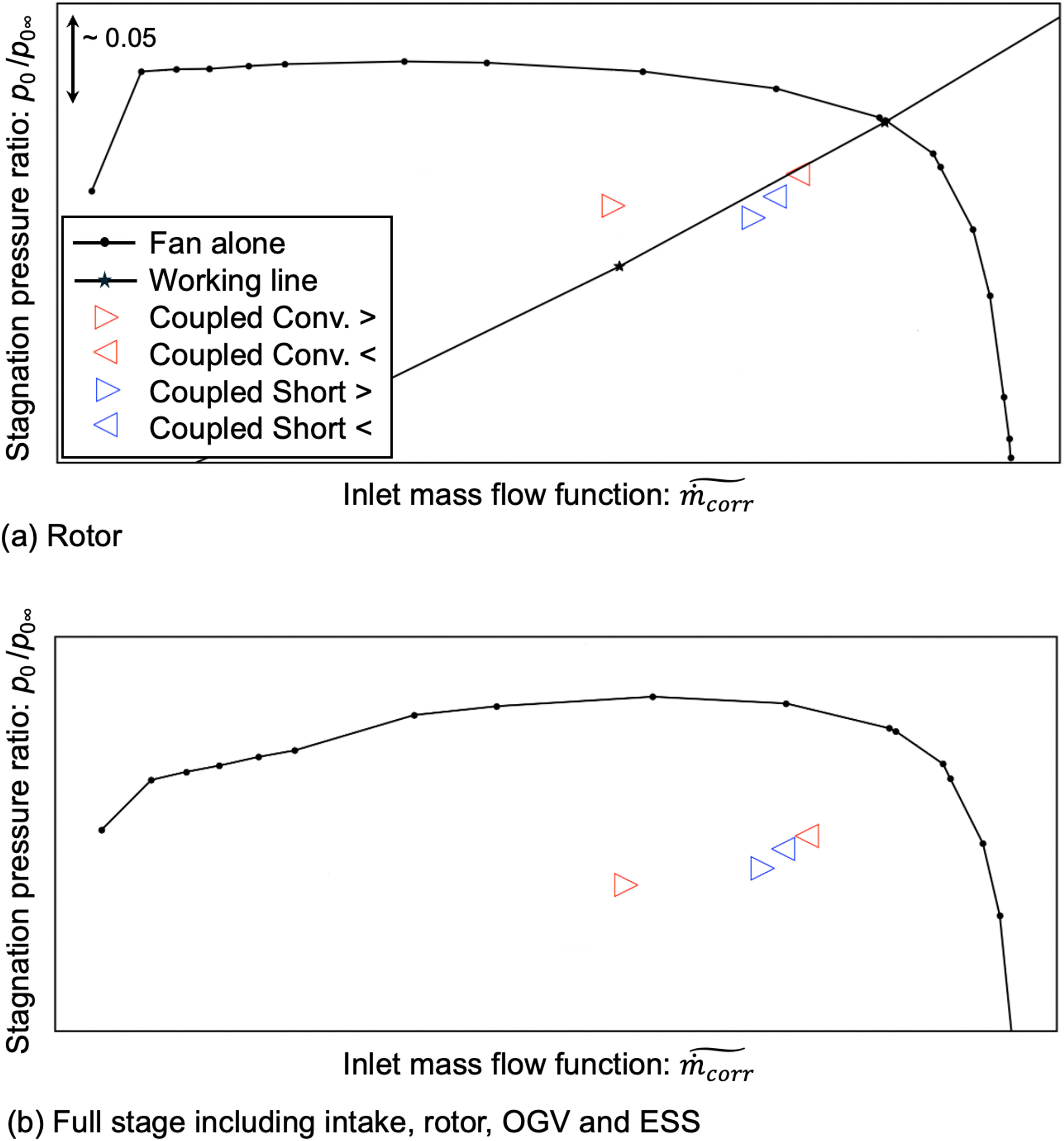
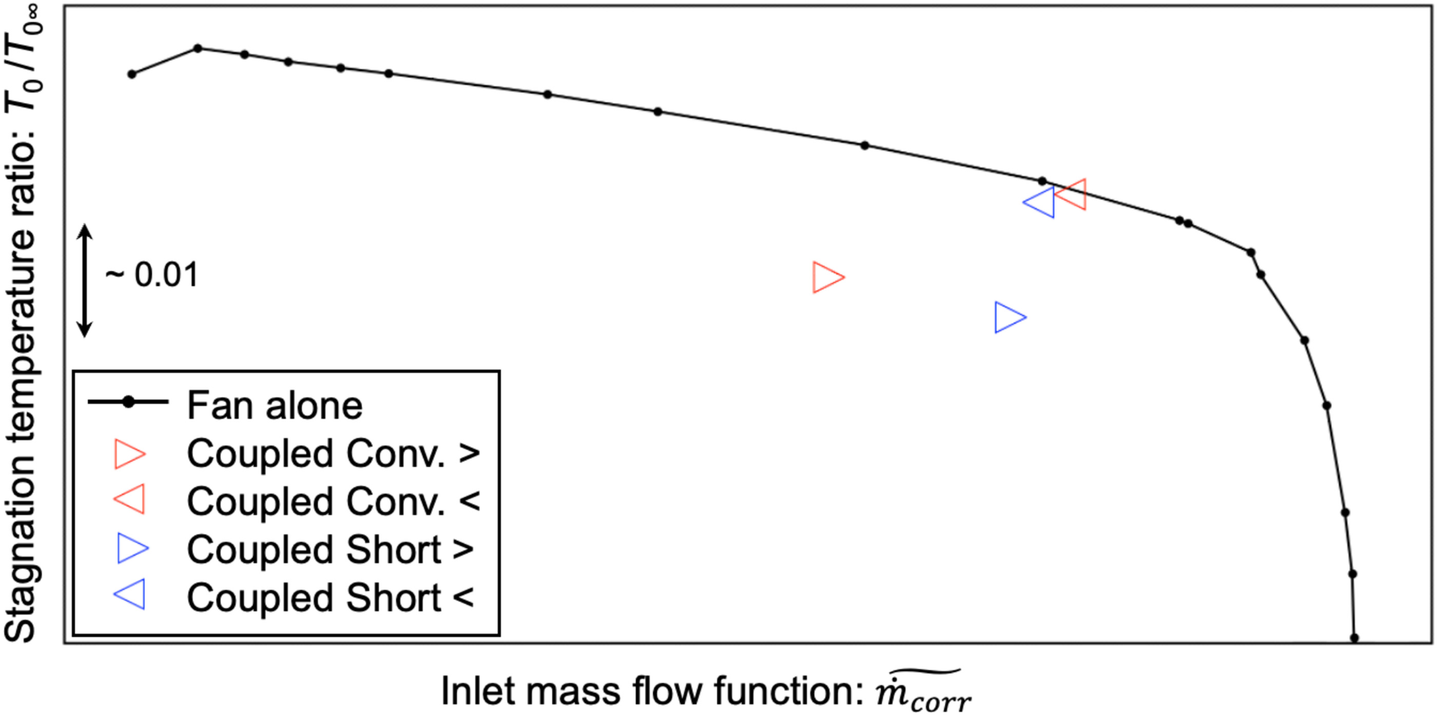
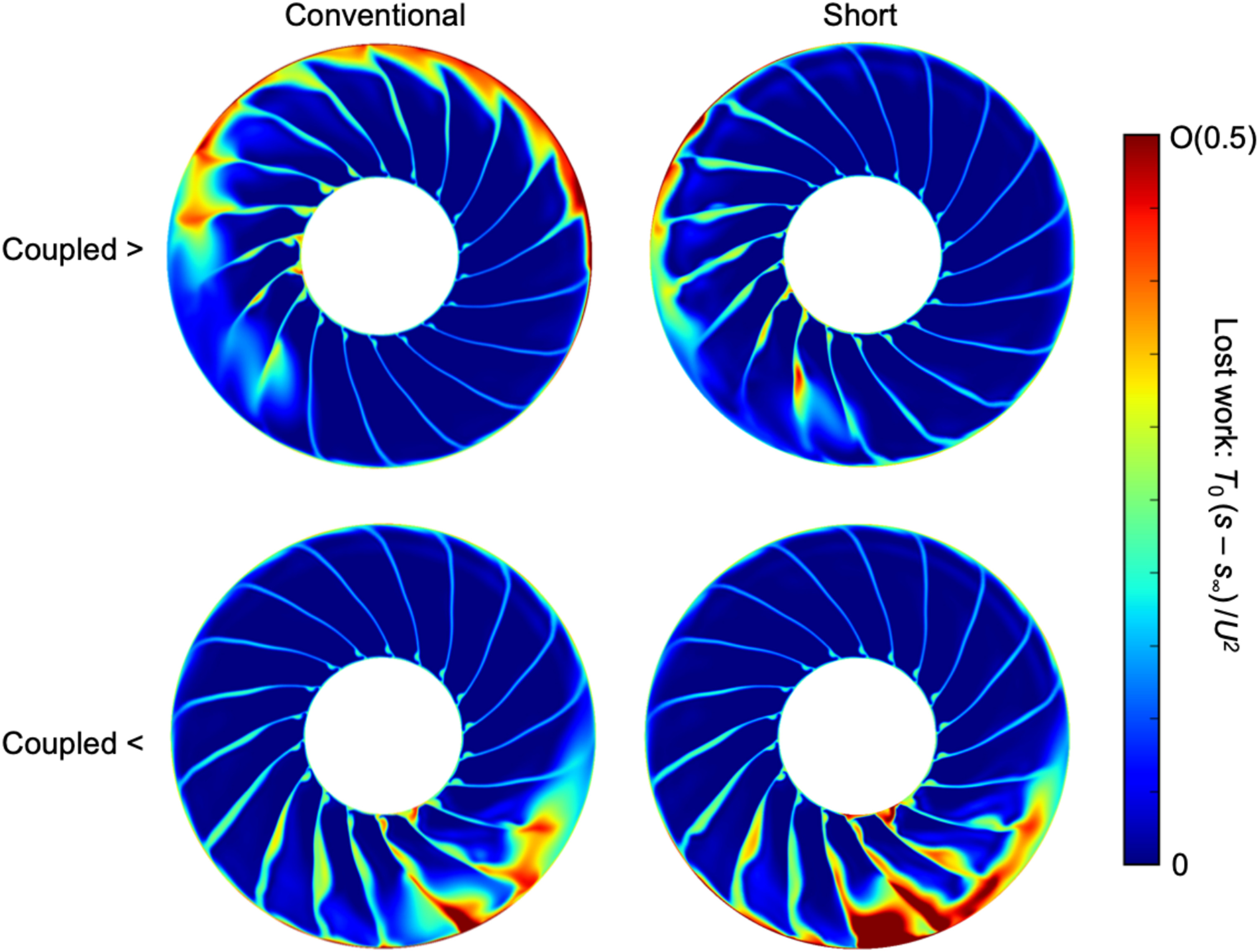
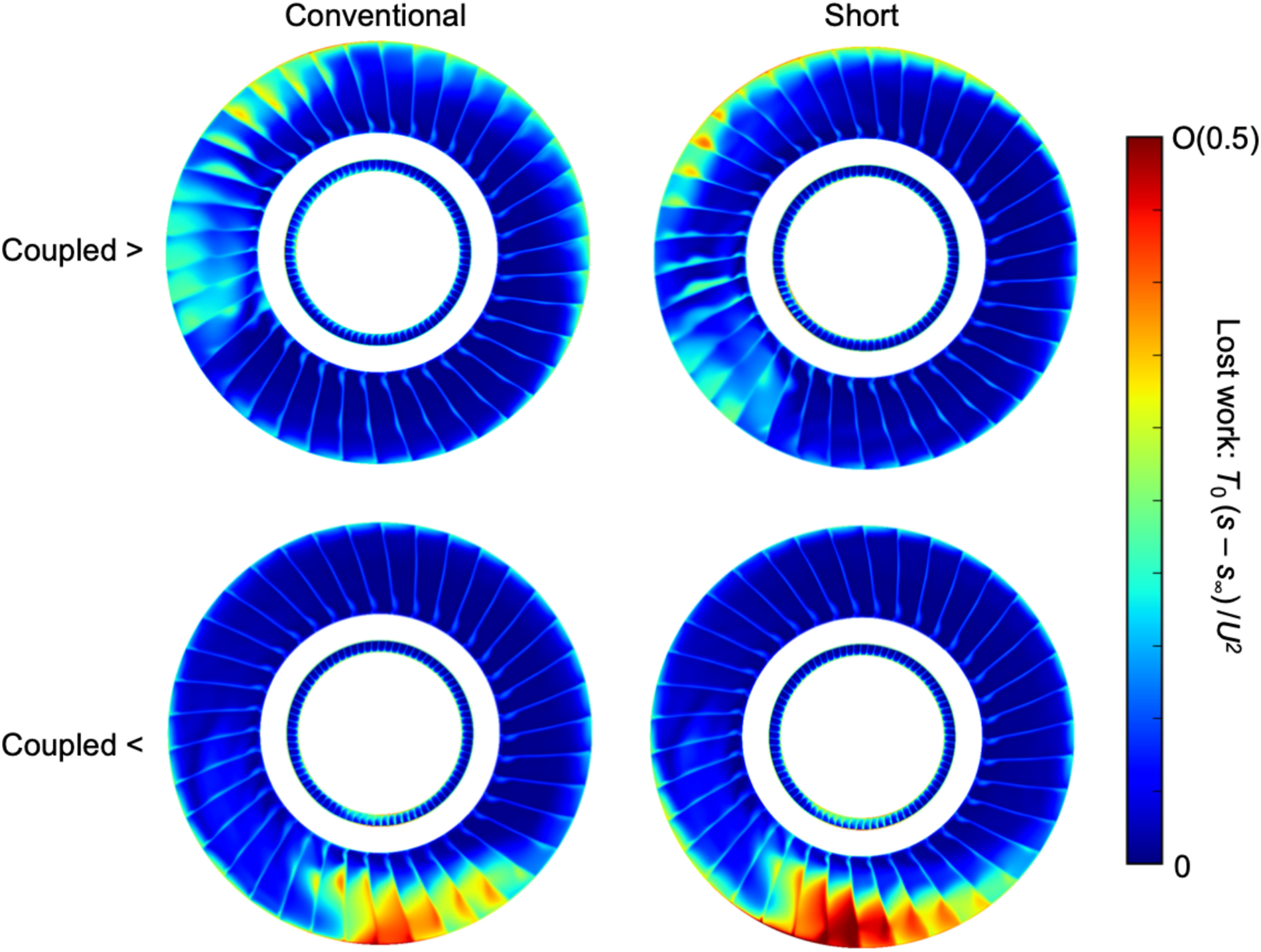
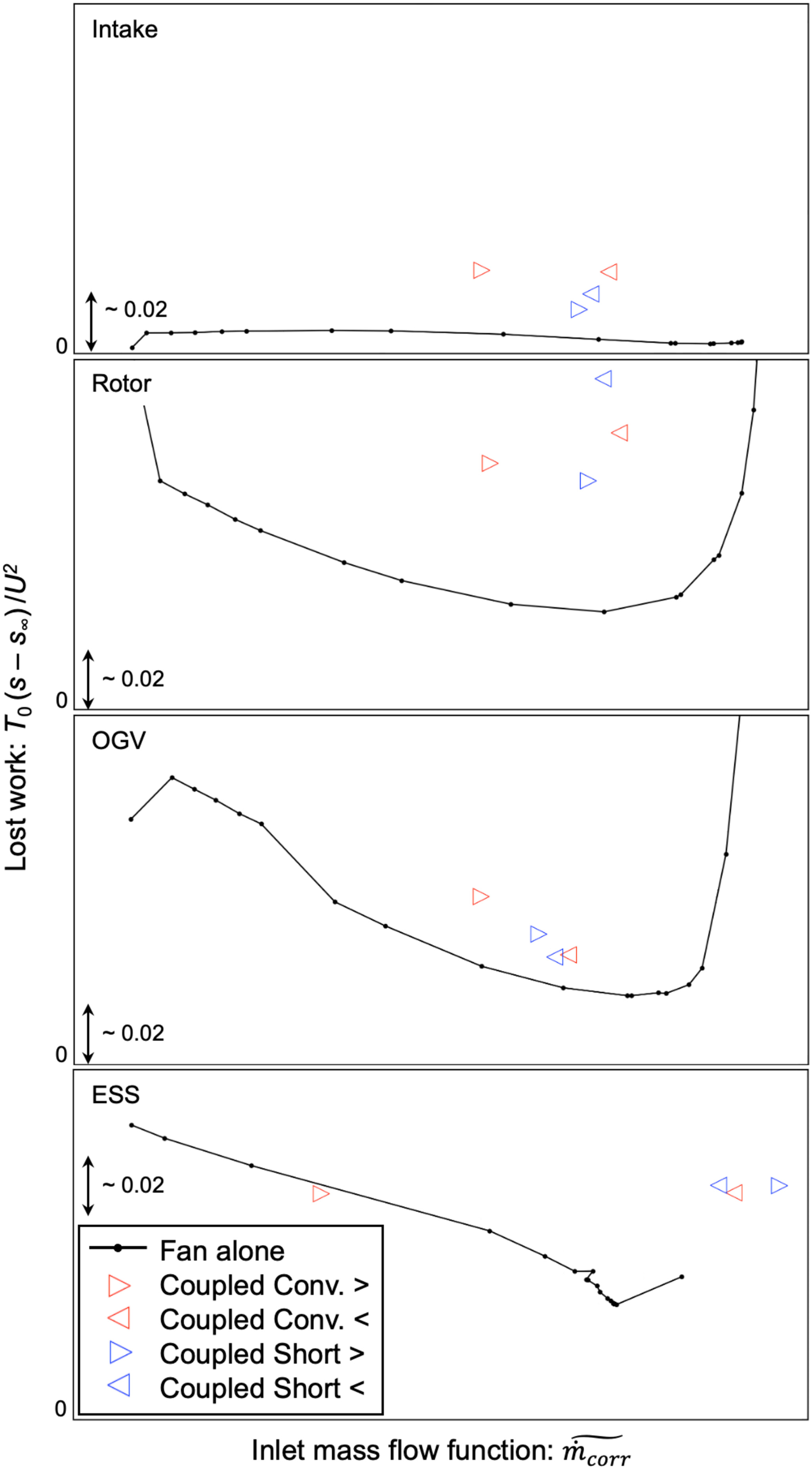
Figure 15.
Time-averaged intake, rotor, OGV and ESS lost work for steady rig- alone and coupled unsteady calculations. All plots have the same vertical axis range such that they show a true loss breakdown.
At this separated crosswind condition, there is little difference between conventional and short intakes in overall full stage performance. It was shown above that in both intakes the flow separates in a similar way at a similar location: shock-driven separation from the highlight. At severe crosswind conditions, the intake can be assumed to be separated. If the separation mechanism is similar in both intake designs, it is to be expected that the impact on the fan will in turn be similar in both cases.
The fan work input is significantly lower when the freestream flows from the left. This effect is large enough that the fan has lower stage pressure ratio for flow from the left than from the right, even though the latter is actually the condition with higher fan loss (c.f. Figures 13 and 15). This is mainly caused by the change in sense of the ground vortex rotation relative to the fan. For freestream flow from the left, the vortex is co-rotating with the rotor, creating an average co-swirl at rotor inlet, and vice-versa. This is superimposed on an ever-present bulk swirl pattern due to flow redistribution, but this component of swirl is irrotational so it does not affect the average rotor work.
Due to the summations of these work and loss effects, the full stage performance shows little bottom-line difference between the two directions of freestream flow. However, this belies the fact that there are considerable differences in the detailed flow field, fan loss sources, overall fan loss and fan work input. It is therefore possible that the different crosswind directions lead to different remaining amounts of stability margin at this condition. This has not been tested here but would be an important consideration and motivates a full assessment of the stability range. It is also possible that different fan designs would react to in a different way; the work input effect depends on the ground vortex but the loss effect is likely to be more sensitive to fan design. It is therefore important to consider these results in the context of the detailed flow field, not just the 1D numbers.
The rotor is the single most severely affected component in terms of loss generation. Nevertheless every component is affected and the stator loss should not be neglected. The loss incurred in the intake itself due to the flow separation is higher for the conventional intake than the short intake due to the additional distance available for mixing before the fan redistributes the separated flow.
Conclusions
The flow field at crosswind depends on multiple features including the freestream momentum and direction, intake droop, ground vortex and fan aerodynamic response. The equilibrium flow field can only be determined by coupled unsteady CFD of the fan, intake and external domain.
The local combination of total pressure and swirl distortion drives the response of the fan in terms of work and loss.
For crosswind from the left (looking into the engine with a clockwise rotating fan) the ingested ground vortex is co-rotating and reduces the fan work. For crosswind from the right, the ground vortex is counter-rotating, which increases the incidence as the fan leaves the windward lip separation. This leads to higher work and casing separations with greater spanwise extent.
A short intake has a more aggressive diffuser reducing the ability of any separated flow to reattach before reaching the fan. The variation of swirl at the fan face is also greater with a short intake, which contributes to a stronger separation for crosswind from the right. However, for a short intake the close coupling of the fan and intake suppresses separation and reduces the loss for crosswind from the left.
Despite the severe fan-distortion interaction, this paper has shown for both short and conventional intakes the low pressure ratio fan considered can operate stably in strong crosswinds without a significant drop in performance.
The physics of the fan-distortion interaction with crosswind can be applied to other fan and intake designs. For example, in the case of an anticlockwise rotating fan, crosswind from the left will lead to a high work and high loss configuration. However, the detailed impact of a different design on the flow-field is unknown and would require further study.