
Introduction
The stability limit of a transonic compressor stage is typically determined by flow effects in the rotor blade tip region, where tip leakage flow leads to a strong secondary flow structure, which forms the tip leakage vortex that travels through the blade passage 1. At transonic blade speeds, this vortex intersects with the passage shock of the subsequent rotor blade and tends to increase in size 12. Intense blockage and inhomogeneous blade loading are caused by highly throttled conditions.
Numerical and experimental investigations have shown the significant influence of the tip leakage vortex behavior on the aerodynamic stability limit of the compressor stage 22.
A rotor is called tip-critical when stall initiation occurs close to the casing wall. Effects, such as breakdown of the tip leakage vortex 21, 10, and spill of fluid around the blade leading edge, are described in literature 23; Bergner, 2007), but were not measured directly in a transonic rotor stage.
Numerical and experimental investigations of subsonic rotors showed that periodic separations of vortices from the blade leading edge occur shortly before the inception of rotating stall. The vortices may be the initiator of a spike 8, i.e., a short-length scale disturbance with high circumferential velocity (>70% rotor speed depending on the setup), developing into a rotating stall cell. The shape of the structures is described as a tornado-like vortex, with one end attached to the rotor blade and the other bound to the casing and traveling towards the adjacent blade 14, 18.
The operability limit may also be determined by mechanical vibrations occurring at highly throttled conditions. Especially at part-speed conditions, the unsteady forces produced by rotating stall cells can lead to large vibration amplitudes 9. For the rotor under investigation, non-synchronous vibrations have been measured across the speed range. A numerical study, using time-linearised computational fluid dynamics, has recently linked these vibrations to the convective transport of tip leakage fluid in the tip region 17.
Measures that influence the structure of the tip flow directly, such as casing treatments, affect the stability limit independently of the aerodynamic or aeroelastic failure mechanism, even though the exact working mechanism is still under investigation 6.
The development of such stabilizing methods requires exact understanding of the phenomena at the stability limit that lead to the breakdown of stable flow conditions.
The literature mentioned indicates that the transient phenomena are located close to the casing wall above 90% span [e.g., 14] and may lead to a convective coupling between adjacent rotor blades. Furthermore a significant influence of tip leakage fluid and it’s spillage around the blade leading edge is described in many publications.
Main objective of the current investigation is to analyze the structure of transient aerodynamic effects prior to full span rotating stall, particularly the occurrence of tornado-like radial vortices separating from the blade leading edge, which were expected from available literature but never resolved directly in experiments, yet. The contribution of tip-leakage fluid to these vortices, indicated by simulations of 24 is analyzed as well.
In order to increase understanding of suspected flow structures, the current investigation aims to achieve the following results:
a) Derivation of the structure of small scale leading edge separations and resulting radial vortices from transient flow field measurements.
b) Detection of the contribution of tip-leakage flow to radial vortices through tracking technique without intake seeding.
c) Analysis of the coherence of radial vortices and non-synchronous blade vibrations prior to rotating stall.
Previous investigations have shown that it is possible to identify the size and structure of the flow at steady operating conditions along the whole design speed-line using ensemble-averaged Particle Image Velocimetry (PIV) 5.
The PIV-System that was already established for steady measurements in this area is used within the current investigation to resolve the described transient flow structures during throttling processes into rotating full span stall.
In a typical setup, seeding particles are homogeneously spread in the inflow of the compressor stage to investigate their movement in the measurement area. In this investigation, the method is supplemented by measurements taken without intake seeding, shortly after regularly seeded measurements. It is possible to investigate the spreading of tip leakage fluid that has picked up deposited seeding particles from the casing wall to show its contribution to the observed radial vortices.
Methodology
The experimental tests were carried out on the Transonic Compressor Test Rig at TU Darmstadt. The rig contains a one and a half stage compressor, which is representative of a modern HPC front stage. The test rig is electrically driven at a maximum speed of 20,000 rpm, reaching tip Mach Numbers of up to 1.4. The operating point is controlled by a variable exit throttle. Steady and unsteady instrumentation is used to measure thermodynamic and mechanical conditions during transient throttling procedures. The rotating strain gauge instrumentation on the rotor, which is sampled via a telemetrical system at a frequency of 100 kHz, is relevant to the results presented here. The presented strain gauge signal comes from a sensor that is sensitive to the first torsional blade Eigenmode.
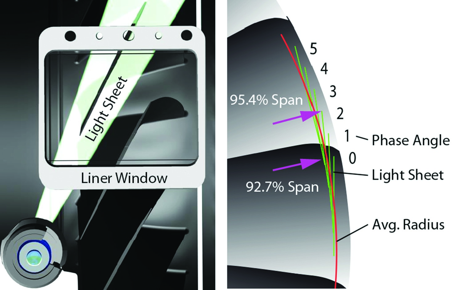
PIV measurements were carried out to analyse the flow in the tip region of the rotor: a tangential light sheet plane parallel to the blade chord, at a minimum of 93% span at the leading edge, was introduced. A stereoscopic camera setup (Figure 1) was used to capture double frames of the flow, which was seeded with oil particles, through a window in the rotor liner. The system was triggered to phase lock the rotor relative position for ensemble averaged measurements. One relative position of the light sheet against the rotor blade is shown in Figure 2. At steady operating conditions, one rotor passage was subdivided into six equally spaced phase angles, as shown in Figure 2.

Petroleum-based smoke oil with a droplet diameter below 600 nm was introduced into the settling chamber as seeding material to capture the high velocity gradients 20. At each phase angle, several hundred images were recorded and evaluated separately using common parameters (e.g., sliding background subtraction, magnification 20px/mm, multigrid correlation with final window size 24x24px/50% overlap, sub-pixel image deformation, Whittaker reconstruction, histogram filtering, no smoothing, [19]). Details of the calibration and evaluation algorithm and further information on the test rig and instrumentation are described by 5. An analysis of the measurement accuracy can be found in 4. For the in-plane velocity shown in this paper, the uncertainty approximates up to 4% of the measured value.
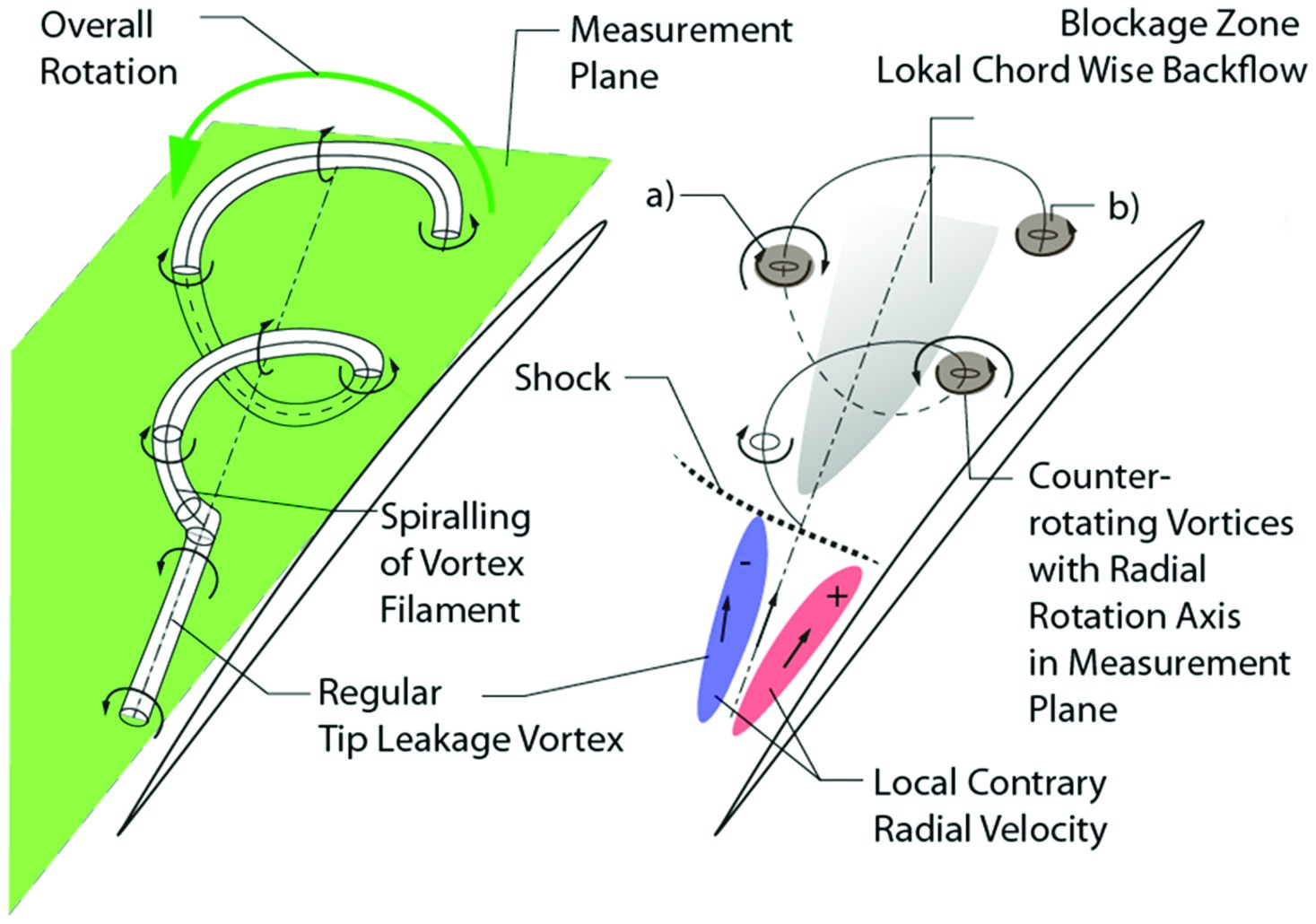
Due to the comparably small diameter of the stage, the 6 independently recorded measurement planes span up in a fan shape, as depicted in Figure 2. Each plane reaches from 92.7% (tangent) to 95.4%. For the iso-surfaces within the blockage zone shown in Figure 4, a volume has been interpolated between the measurement planes on a structured polar grid.
The methodology described by , based on streamline integration vector placement, was applied to improve the visualization of instantaneous vector fields. The algorithm published by 11 was used to identify local vortex structures in the two-dimensional velocity fields. The blade tip displacement was detected using image intensity gradient based edge detection in the PIV images. The local throat width was derived by measuring the perpendicular distance towards the adjacent suction side from the leading blade.
Results and discussion
Steady PIV measurements
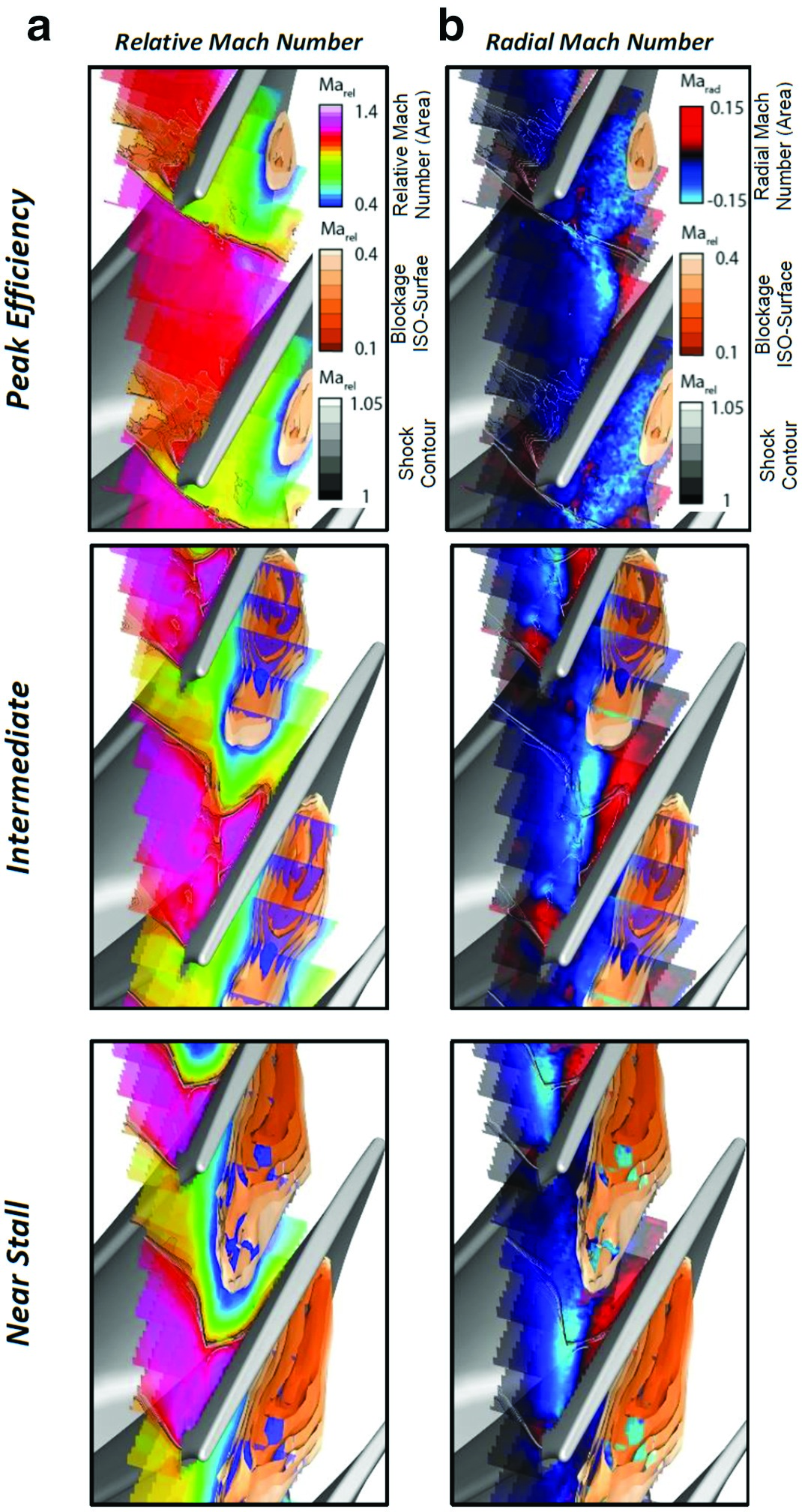
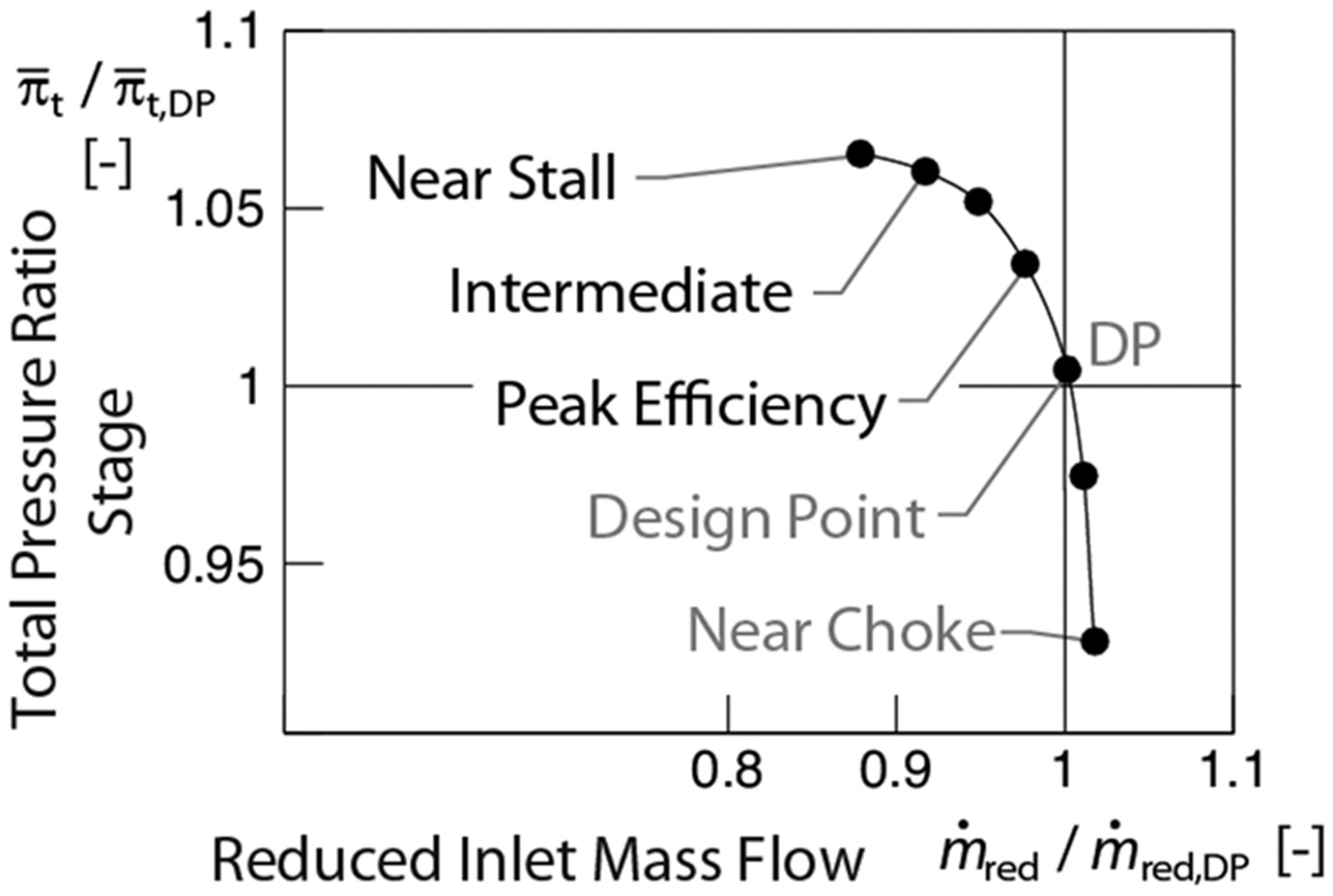
Ensemble averaged PIV measurements were carried out at three operating points (Peak Efficiency, Intermediate and Near Stall) on the design speedline shown in Figure 3.
The relative Mach-Number in the light sheet plane (Figure 4) is compared to the radial Mach-Number (Figure 4). The relative Mach-Number shows the position and the structure of the shock around Marel = 1 and the blockage zone with low velocities Marel < 0.4. The contours of the shock position are superimposed (grayscale legend) on the radial Mach number results for orientation. Within the three operating points shown, consistent detachment of the leading edge shock correlated to the throttle degree can be observed.
The blockage zone simultaneously increases in size and moves upstream. The orange shaded iso-surfaces of constant low relative Mach Number show that the center of the blockage zone is located in the downstream part of the passage, where the measurement plane reaches radial positions over 95% span (compare to Figure 2).
The time averaged secondary flow structure can be derived by analyzing the zones of contrarian radial velocity, shown in Figure 4. The tip leakage fluid enters the measurement plane in the blueish zones in negative radial direction and rolls up around the blockage zone. Close to the suction side, the fluid of the resulting vortex appears in the measurement plane with positive radial velocity. These ensemble averaged measurements show that there is no negative axial velocity within the blockage zone at all steady operating points 5, whereas evaluation of individual frames at near stall highlights local backflow regions.
Transient PIV measurements
Figure 5 shows raw images of the rotor section under various conditions. Seeding particles were inserted into the stage intake during measurement (Figure 5). They appear in the entire illuminated area inside the blade passage and upstream of the rotor. Figure 5 to Figure 5 are images taken while the intake seeding was being shut down, where particles only appear within the tip leakage vortex and not upstream of the rotor. Condensed fluid was previously carried away from the casing wall by the tip flow and transported to the measurement section at 93%–95% span.
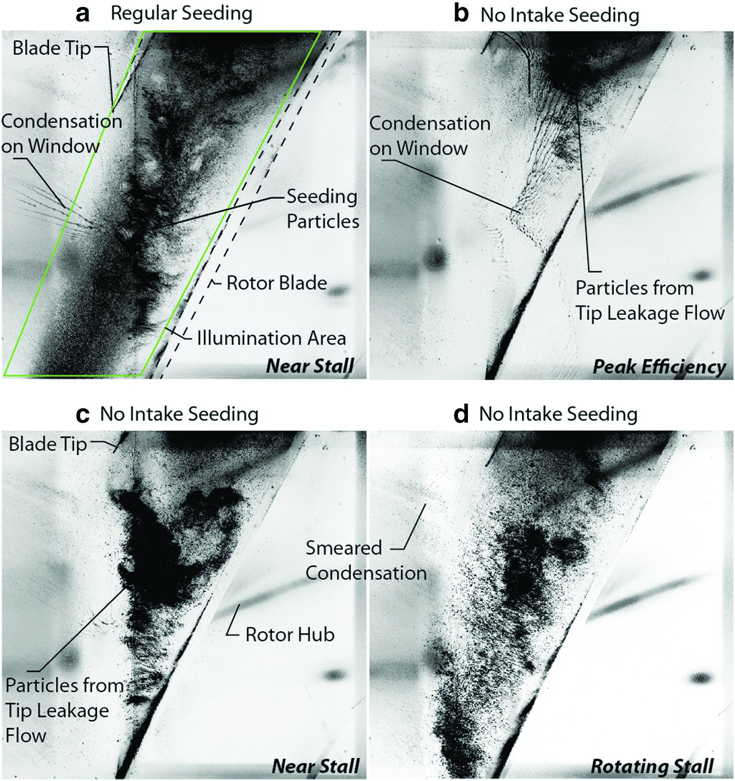
These particles can be used to track tip leakage flow. It is not possible that fog from condensing intake air humidity is responsible for the observed particles due to the thermodynamic circumstances (rel. intake humidity 34%, 286 K, 988 mbar) during measurements.
Both measurement types could be evaluated using conventional PIV algorithms to analyze the flow field.
Several transient runs to rotating stall were carried out, with both setups at different rotor phase positions at a recording frequency of ~10 Hz. It is not possible to analyze the time resolved development of the occurring structures but to get several snapshots during the transient throttling procedures, which took about 8 seconds from steady near stall condition to rotating stall. The initial condition and the throttling speed were kept constant within each run.
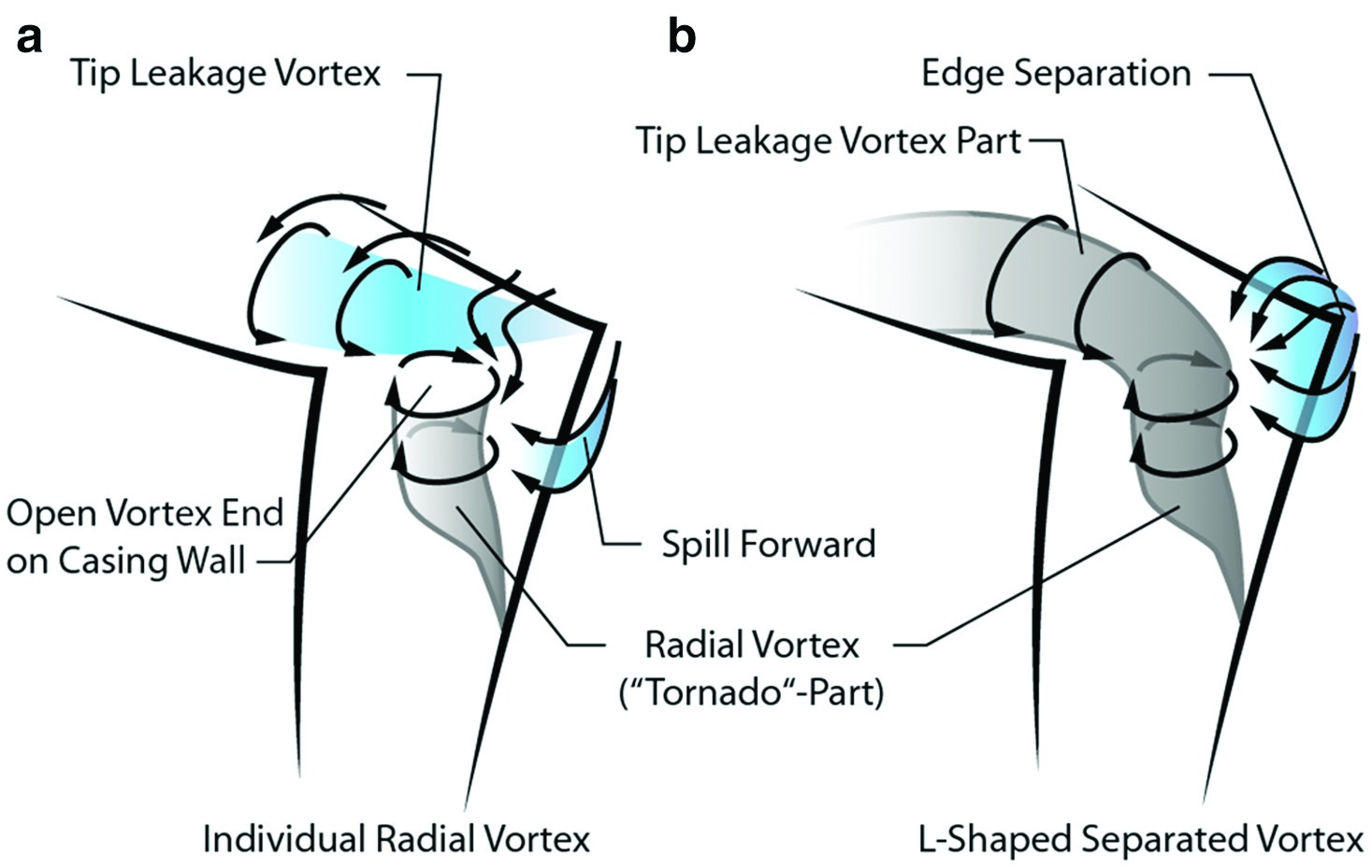
Figure 6 shows a typical flow field as it occurs at steady, near stall conditions. The tip leakage flow spreads uniformly throughout the whole blade passage and reaches the next blade. Downstream of the shock, a blockage zone with low relative velocity develops. Within this blockage zone, a small area with chord-wise backflow appears, which is strongly time dependent between several snapshots. The fluid that enters this backflow region comes from counter rotating vortices located in the boundary of the blockage zone. The presented results clearly show that a breakdown of the tip leakage vortex as described in literature 16, 10 is present in the compressor under investigation. The initial tip leakage vortex filament eventually bends at a specific point and rolls up around a core region with local backflow. This system is cut by the measurement plane, where the vortices are as depicted in Figure 7.

Under steady operating conditions, seeding material is only present within the tip leakage vortex region. During the transient throttling procedure, strong fluctuations in seeding density are visible in the upstream part of the suction side. Figure 8 shows how fluid from the leading blade passage is spilled around the blade tip and draws seeding material from previous tip leakage flow (spill forward).
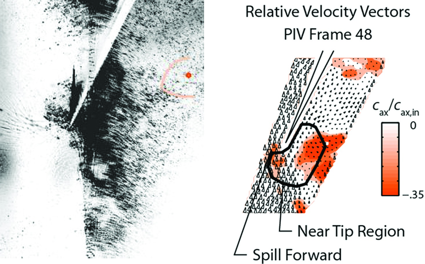
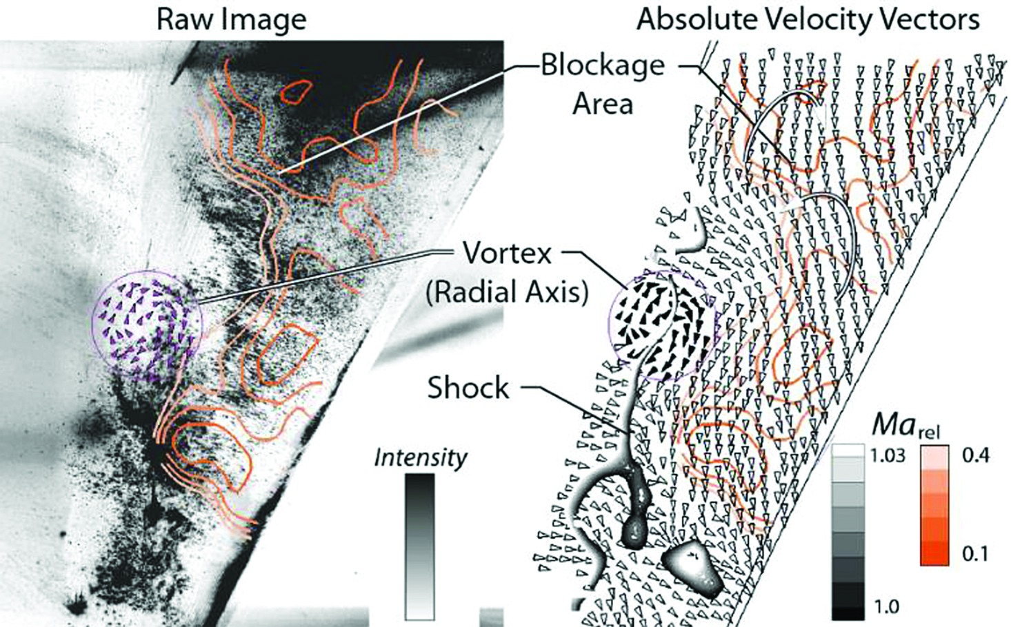
As a result, a small subsonic zone develops at the blade suction side upstream of the passage shock, which is caused by a leading edge separation, depicted in Figure 9. In this interaction region, a vortex with radial rotation axis is developing near the suction side (Figure 9) and clearly visible in mid-passage (Figure 10).
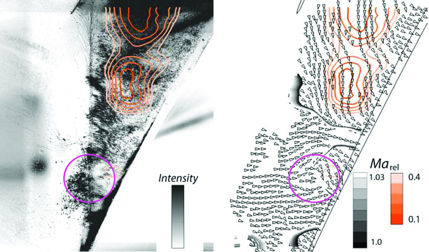
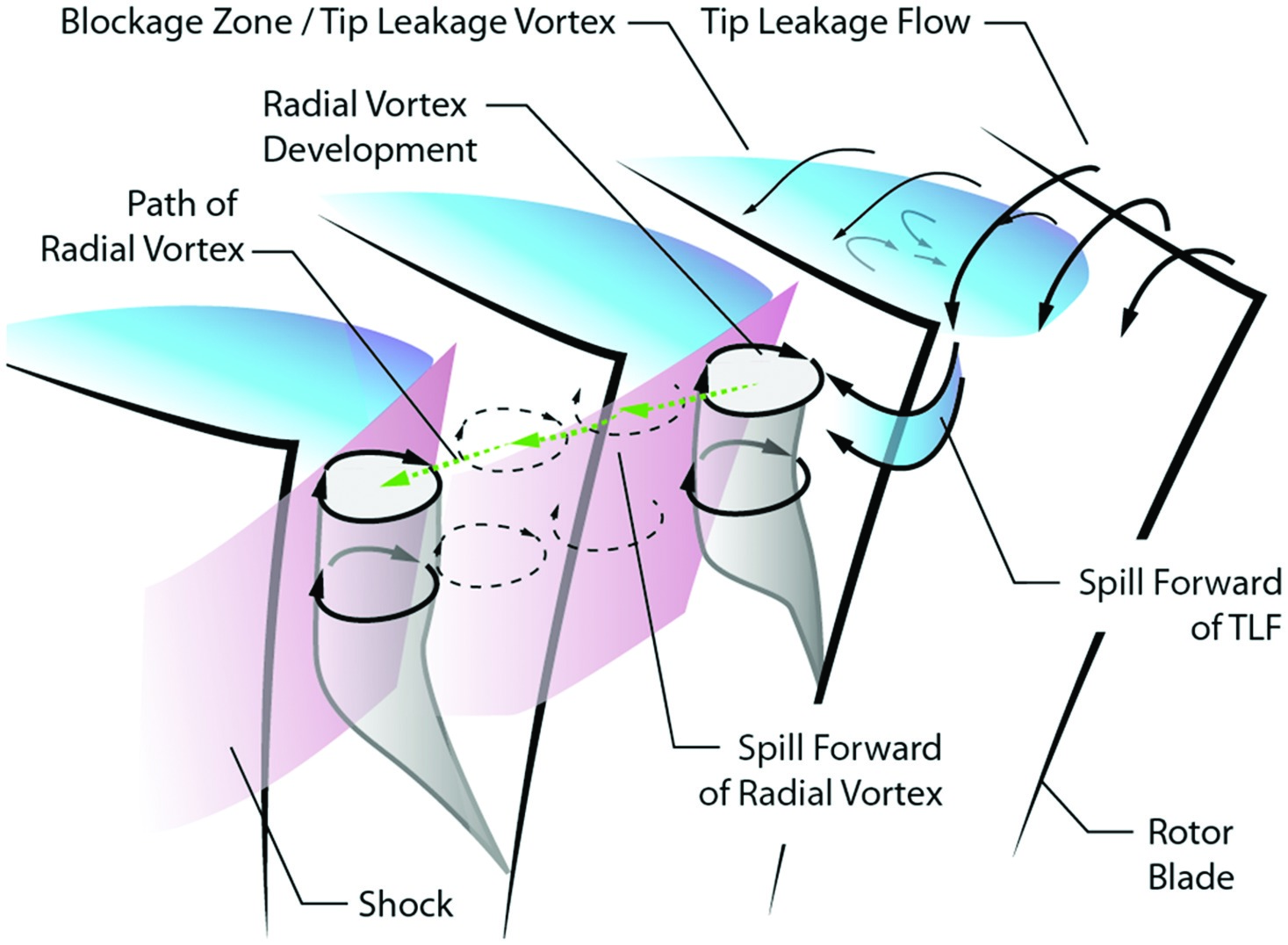
The radial vortex was observed in several frames during the transient throttling process. Several snapshots are depicted in Figure 11. The vortex travels around the blockage zone towards the leading edge of the next blade. Its geometrical size exceeds the previously described structures in the boundary of the blockage zone. When impinging on the leading edge, the vortex causes significant variations in the flow direction and velocity in the tip region. It influences the local blade loading, eventually leading to another spill forward and subsequent flow separation.
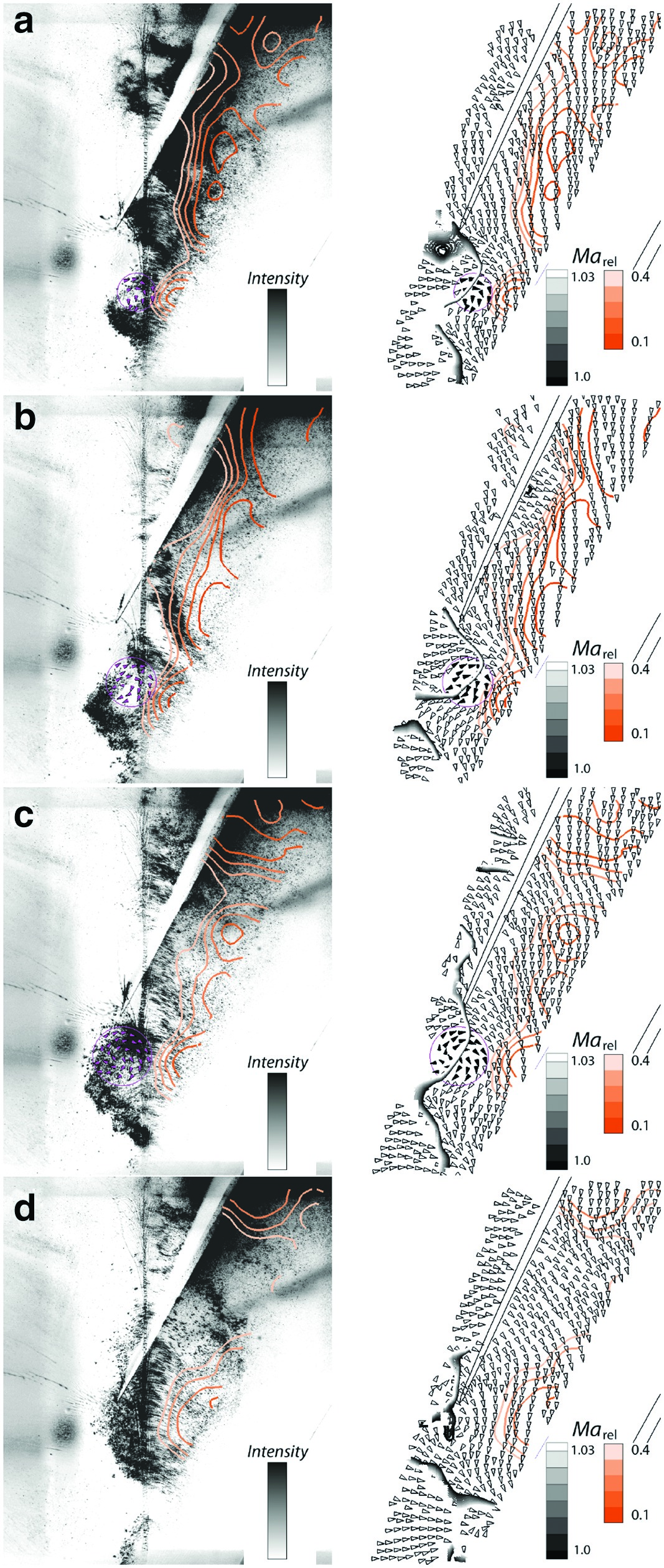
Figure 9 to Figure 11 show raw-images and the corresponding absolute velocity vector field with superimposed contours of the shock (grayscale, Marel 1:1.03) and the blockage zone (orange Marel 0.1:0.4). Radial vortex regions are highlighted.
Once the described pattern has established, it is self-sustaining and travels around the circumference, as depicted in Figure 12. This agrees with the system described by 14, and was recently documented by 18 for a subsonic compressor. The measurements cannot be used to determine whether the tip leakage vortex is part of the shed radial vortices or remains attached to the blade. It is assumed that the radial vortex merges with new tip leakage flow in the interaction region with the passage shock (Figure 13). A further possible vortex separation schematic is shown in Figure 13, which depicts how an L-shaped separation across the blade tip leading edge could occur. Further investigations are necessary to determine the exact separation shape, whereas the first one is more likely to occur due to the significant forward sweep of the rotor blade.
The investigation shows that radial vortex structures appear due to local flow separations from the blade leading edge. In numerical investigations (e.g., [18]) these vortices quickly develop into a spike, which then grows to a rotating blade stall cell within a few revolutions.
For the compressor under investigation, the radial vortices occur alongside large blade vibrations over a longer period of time until a rotating blade stall cell with massive backflow appears as discussed in the following section. In the period, when the traveling radial vortices are observed, the rotating strain gauge instrumentation shows continuous growth of stress amplitudes.
Comparison to blade vibration
Figure 14 shows the frequency analysis of the transient strain gauge recording during a throttling procedure. Before rotating stall occurs at revolution 0, a significant rise of the non-synchronous blade vibration amplitudes in Engine Order 5.8 occurs, which coincides with the first torsional Eigenmode of the blade 6. The band-passed filtered amplitude of this frequency in Figure 14 shows the continuous growth of the vibration, starting around 700 revolutions before rotating stall (detected via synchronously measured unsteady wall pressure).
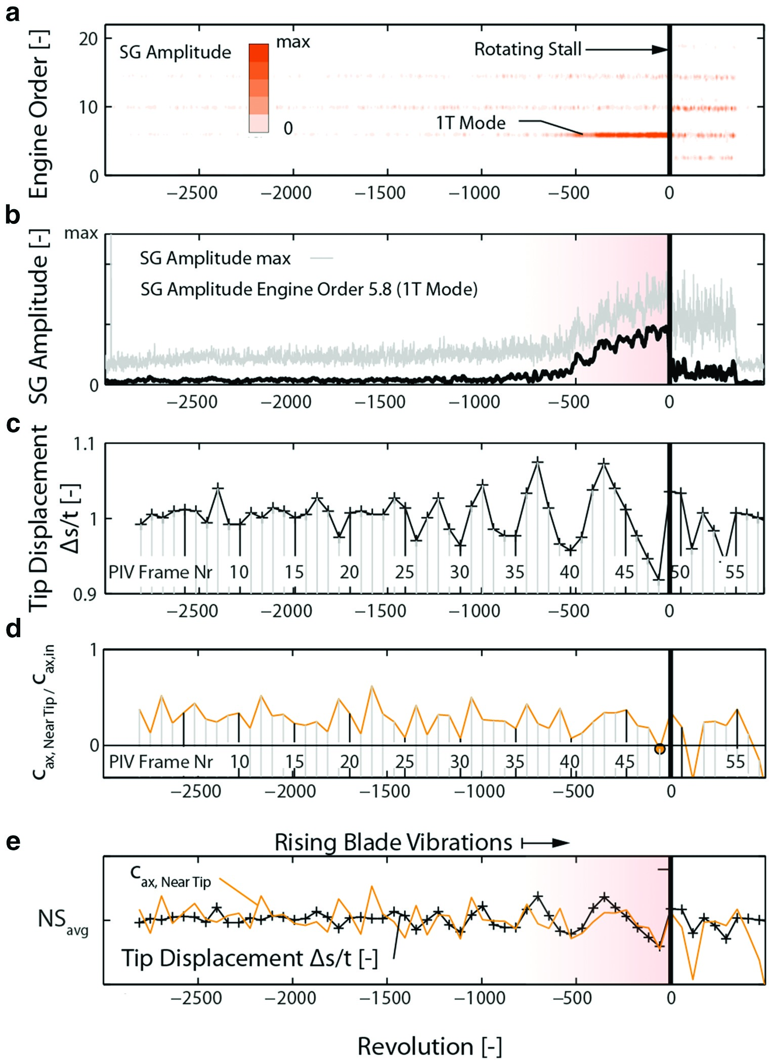
The tip displacement was measured via edge detection in the transient PIV images, showing the normalized throat width at the blade leading edge in Figure 14. Due to the low sampling rate, this signal is heavily aliased. The measured tip deflections amount to over 7% of the rotor pitch during the last 1,000 revolutions before stall.
The average axial velocity in the region around the blade tip (Figure 8) where the previously described vortices impinge is depicted in Figure 14. During the whole recording, several frames show very low axial velocity close to axial stagnation. For frame 48 (Figure 8), the average axial velocity around the tip drops below zero, leading to fluid spill around the leading edge around 50 revolutions before rotating stall.
Figure 14 shows a large negative tip deflection for this frame, corresponding to the reduced blade loading because of the forward spill separation at the leading edge. The combination of the deflection signal and the axial tip velocity in Figure 13 shows that this correlation is present in the last 1,000 revolutions before stall. At steady, near stall operation and during revolutions −3,000 to −1,000 in the measurement, significant variations of the tip flow occur but are not correlated with blade vibration.
The radial vortices travelling around the circumference in the leading edge region are responsible for deflections of the blade tip but do not directly lead to stall. However, the results suggest that there is a feedback mechanism between the aerodynamic fluctuations, i.e., the transport of radial vortices, and the mechanical vibrations. The local rise in incidence, due to vibration in the first torsional mode, promotes leading edge separation and leads to the formation of radial vortices. Aerodynamic disturbance and vibration thus become phase-locked. This mechanism is very prominent since the mechanical damping of the rotor blisk and the variation of the torsional eigenfrequency between the blades is very low. Thus, a coherent structure between travelling vortices and a mechanical blisk mode establishes.
This phenomenon is not self-induced by blade vibrations but depends on the time-scale of the vortex transport.
These findings imply that it will be very difficult to predict compressor behaviour near the stability limit. Modelling the aeroelastic interaction between the blade vibrations and the radial vortices requires sophisticated, full circumference simulations with bi-directional coupling. The large size of the involved vortex structures allows the use of relatively coarse grids in the passage, making such simulations feasible in principle. The currently widespread approach of predicting aeroelastic stability using the energy method, which computes aerodynamic damping from the work input to the blade at constant (small) vibration amplitude, should be used with caution since it does not allow feedback from the fluid to the structure. Reduced domain models with periodic or phase-lagged boundary conditions artificially fix the wave number and propagation speed of the aerodynamic disturbance and may give misleading results.
Nevertheless the results may be very helpful during the design process of compressors. The described self-sustaining aeroelastic process of separating vortices exciting torsional mode blade vibrations is enhanced by a symmetric system. Intentional mistuning of the rotor blades could be beneficial to suppress the coherent amplitude rise of aerodynamic disturbances and blade vibrations. Furthermore, measures like casing treatments which inject fluid near the casing wall are suitable to either prevent the radial vortex separation or their propagation in order to improve the operating range of a compressor showing this type of instability.
Conclusions
A combination of optical and mechanical measurement systems was successfully applied to investigate transient effects that occur prior to rotating stall in a transonic compressor test rig.
The structure and breakdown of the tip leakage vortex at near stall condition could be resolved by sequential measurement with shut down flow seeding. The main findings of the investigation regarding the observed transient flow structures are:
a) For the first time, radial vortex structures, which may lead to spike-type stall inception, were visualized inside a transonic rotor and located on a path between the rotor leading edges.
b) It was experimentally confirmed, that former tip-leakage fluid contributes to the radial vortices and is spilled around the subsequent blade’s leading edge. As a result, the flow separates from the leading edge whereupon a new radial vortex is shed.
c) Through the combination with blade vibration measurements, correlation of axial velocity around the blade tip and tip deflections was derived and used to interpret a non-synchronous vibration mechanism that could be misinterpreted as typical flutter 15. When the spill of fluid around the blade tip first occurs, the blade vibrations are at a comparably low level and no strict circumferential pattern is determined. Within several hundred revolutions, the vibration amplitudes reach safety critical levels and blade stall occurs. Based on these findings, the rise of blade vibrations prior to rotating stall correlates with the rotating vortex separation mechanism, which leads to a circumferentially distributed disturbance with a specific convective propagation velocity. The structure reacts in a specific vibration pattern with each blade vibrating in the first torsional mode and a nodal diameter determined by the aerodynamic disturbance. When the vibration amplitudes are large, a significant feedback from the structure can trigger the vortex separation whereas structure and aerodynamics are phase-locked (Figure 14, ca. rev. −500 to 0) and the mechanism is self-sustaining. However, the initial excitation is an aerodynamic forcing mechanism.
Further investigations will include time resolving instrumentations in the steady and rotating frame to identify resulting wave characteristics at part and design speed.
Furthermore, the dependency on tip clearance, part-speed operation and eccentricity will be addressed. The presented methods have proven suitable for the described investigation, whereas great potential lies in the combination with time resolving measurement systems to detect statistical quantities of the relevant phenomena.
Nomenclature
cax
Axial velocity
cax,in
Average axial velocity at stage inlet
cax,Near Tip
Average axial around leading edge (Figure 8)
DP
Design point
EO
Engine order
Marel
Relative Mach-Number
Marad
Radial Mach-Number
PIV
Particle image velocimetry
SG
Strain gauge (rotor mount)
t
Circumferential blade spacing (pitch)
1T
First torsional blade Eigenmode
vchord
Relative chordwise velocity