
Background and conventional wisdom
Due to its high pressure, high temperature, and high speed operating conditions, the complex OTL flow in the gap between unshrouded rotor blade and casing in HP turbine stages has been the focus of turbomachinery research community over the past decades. Reviews of the past understandings and conventional wisdom have been provided by 5, 6, 11 and 13 in the VKI Lecture Series in the early 2000s. Some conventional wisdom and general practice are briefly reviewed here.
Typical modern unshrouded tip design concepts were mostly initiated by the aerodynamicists with the primary goal to control the OTL losses. According to 4 and 9, the OTL loss could account for as much as one third of the total losses in a HP turbine stage. The primary driver of the OTL flow is the pressure difference between the pressure side and suction sides of a turbine rotor blade, and it is the “pressure driven” mechanism which has formed the basis of conventional understanding of the tip leakage flow and the starting point of consideration of controlling it. Accordingly, modelling and reducing tip discharge coefficient has been the focus of many past studies (to name a few, 3, 16, 1). Squealers and winglets have been used as typical tip designs to decrease driving pressure gradients, reduce the leakage mass flow and overall OTL loss 14, 31.
The high contribution of the OTL loss to the overall HP turbine performance gives the dominance of aerodynamic considerations in tip designs and performance optimizations. Also in line with the common practice for turbine blade main flow path, tip aerothermal designs thus have a clear hierarchy (and sequence): (1) Design/optimize a blade tip configuration without cooling; and (2) Add cooling to the “designed/optimised shape.” The two parts of the sequential design also have seemingly well-defined functions respectively: the uncooled shape design selection is aimed at reducing the OTL flow and its losses for performance. And the cooling part is simply aimed at achieving a desired durability for the given aerodynamically designed configuration.
Tip thermal management has been treated similarly to the cooling designs of other hot components, such as main path blade surface and end-walls. The primary intention of film cooling is to supply a passive coolant “film” to the surface without altering the baseline flow. Tip cooling design has been following the same philosophy. For example, a series of film-cooling holes are often placed on the pressure side of the near-tip region 19. In this design, the coolant is expected to passively follow the incoming flow and effectively cool the pressure side edge (rim) with minimum influence on the leakage flow. The cooling hole placement strategies within the tip cavity region remain unclear due to limited understanding of the three-dimensional flows. It has been admitted that, in practice, most blade tip film cooling designs are still achieved through experiences, not pre-test analysis 6. In general, a conventional aero-to-thermal “additive” sequential approach has been adopted in the past tip research and design process, with a default assumption that the aerodynamic ranking established for an uncooled blade tip geometry will not be markedly altered by the following cooling design.
Another common observation, largely based on well-established experimental results at low speed conditions, is a close “correspondence” between aerodynamic loss and heat transfer: larger tip gaps result in more OTL loss, and higher heat transfer 34. In a simple and basic term, this should be regarded as being in keeping with the Reynolds analogy. For a given tip configuration, a larger tip gap is inevitably associated with a larger OTL flow with higher bulk flow velocity. The corresponding higher shear stresses should lead to higher heat fluxes, thus higher heat load for a given surface area. This aero loss-heat transfer “correspondence” should also somewhat underline the aerodynamics-dominant considerations in a tip design, albeit changes in surface area between different tip configurations.
Our basic understanding on OTL flow physics began with many low speed or subsonic cascade experiments (2, 16; “super-scale” linear cascade by 27, 28, 18; etc). These tests simplified the problem with relatively lower costs. Database with greater details and relatively low experimental uncertainty was provided to validate the numerical tools, and to reveal the governing loss generation mechanism and related heat transfer. The blade loading, Reynolds number and key geometry parameters are generally matched during the scaling process from high speed to low speed conditions. A redesign of the blade profile is required, particularly for HP turbine blade, reducing the Mach number usually means a relatively “thicker” blade. It is questionable how the resulting local pressure gradient for OTL flow can still be closely matched with the same loading (pressure difference) but a changed tip geometry. This leads to an additional compromise in addition to the compressibility effects in a high speed flow.
High speed full-scale rotating facilities have been another major source for validation and evaluation of OTL aero-thermal performance for gas turbine manufacturers 23, 10, 29, 35, 17. The majority of these facilities are of a short-duration type. It has been a challenging task to obtain truly full-coverage data with point measurements such as pressure taps and thin-film gauges.
Based on the experimental and numerical efforts the authors have been involved in high speed flows during the past ten years, this overview will purposely highlight the new findings with clear contrast to some of the conventional wisdoms. Emphasis is placed on some fundamental OTL flow physics particularly in a high speed condition. Attention is directed to how these newly established understandings have led to new aerothermal management concepts, and future prospects with respect to blade aerothermal design and analysis. The overview begins with aerothermal characteristics of uncooled blade tips, followed by discussions on the aero-cooling interactions. Finally, a research outlook is given.
Aero-thermal performance of uncooled blade tip
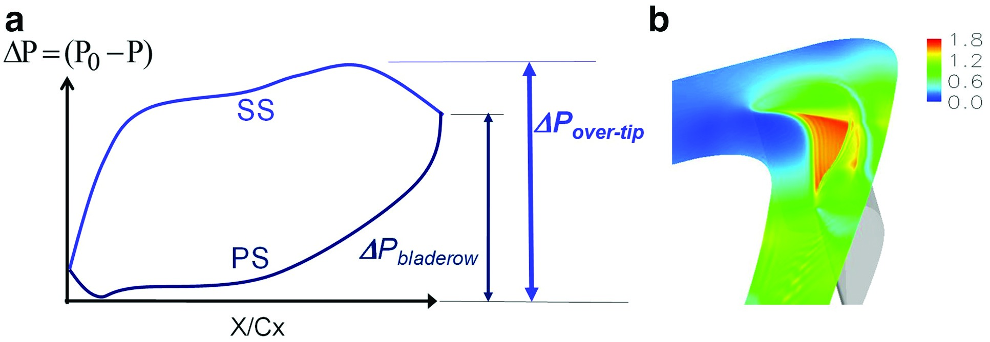
It is common for a modern HP turbine blade to have a passage exit Mach number around one or even higher. In such cases, the maximum driving pressure difference for OTL flow is set by the low pressure peak on the suction surface, which should be always larger than the blade row pressure difference at the passage exit (Figure 1). Therefore, the OTL flow should start to become choked before the blade passage becomes choked 40. Figure 1 shows that a very large portion of OTL flow is supersonic and the peak Mach number can go up to 1.8 39. The transonic nature of OTL flow has also been recognized by some previous work 24, 7, 13, 12; etc.).
Figure 1.
(a) Typical pressure distribution for a turbine blade (Zhang and He [24]), (b) Mach number contours along mid-gap plane (Zhang and He [25]).
Shock wave signatures on heat transfer
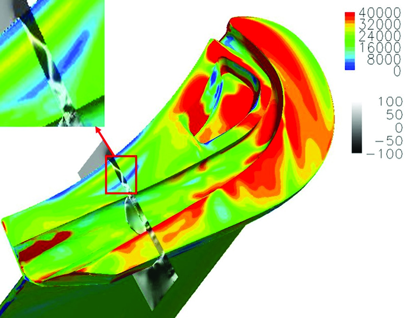
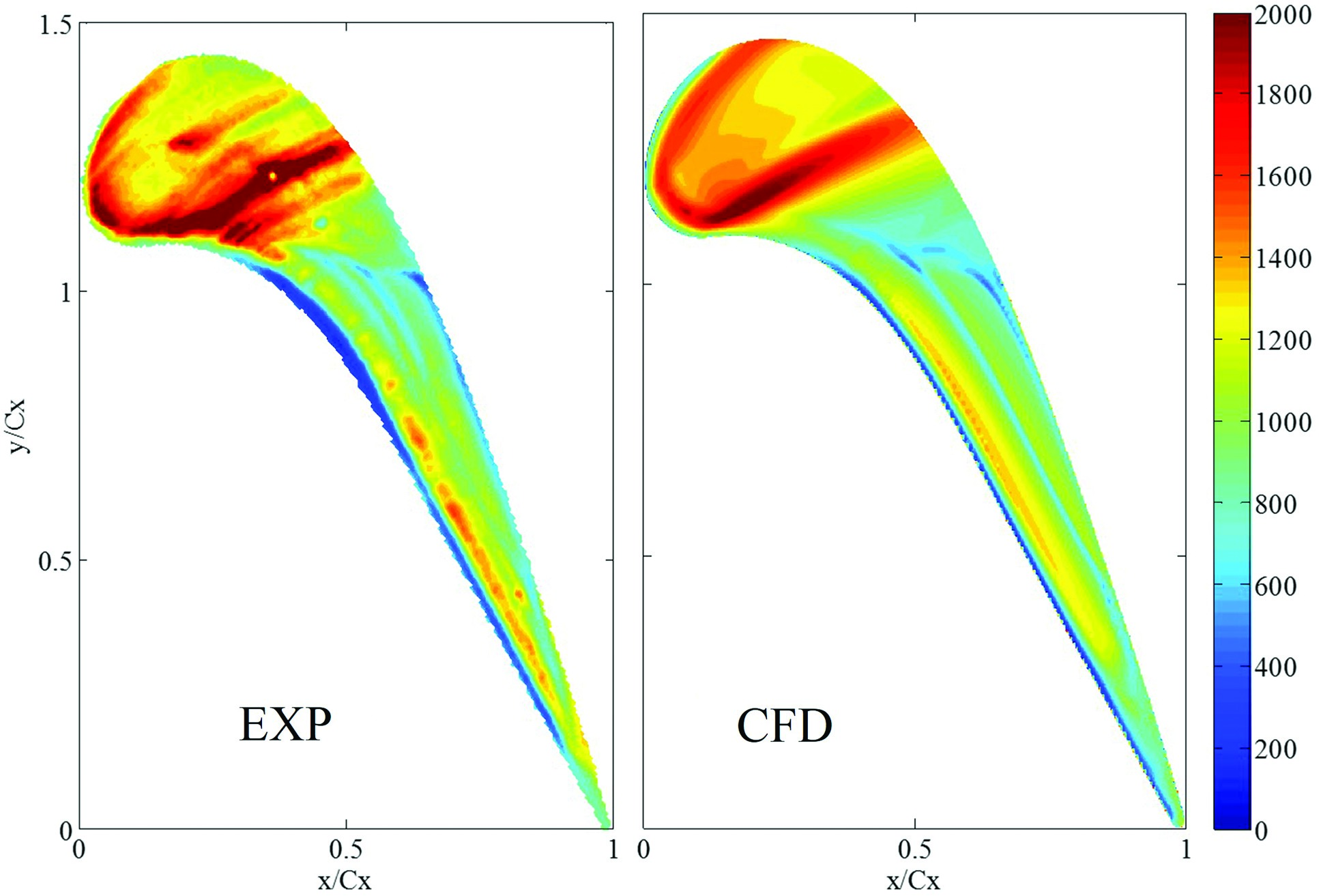
39 reported the first-of-the-kind detailed experimental evidences of the heat transfer stripe distributions caused by shock wave structures over the tip. Figure 2 presents spatially-resolved heat transfer data obtained using the transient infrared thermography technique in a high speed linear cascade facility. Most of the spatial heat transfer variations on the tip surface are well-captured by Computational Fluid Dynamics (CFD) (S-A turbulence model), as shown in Figure 2. Virtual Schlieren visualizations from the CFD analysis demonstrates that the stripe variations of heat flux after the mid-chord correspond to those flow features associated with the over-tip shock wave boundary layer interactions (Figure 3, 39). Similar shock wave signature on heat transfer was also identified for a winglet tip design (Figure 4, 26).
Figure 4.
Tip surface heat flux contours and density gradient contours over a winglet tip surface. (O’Dowd et al. [31]).

Overall heat transfer characteristics in high speed flow
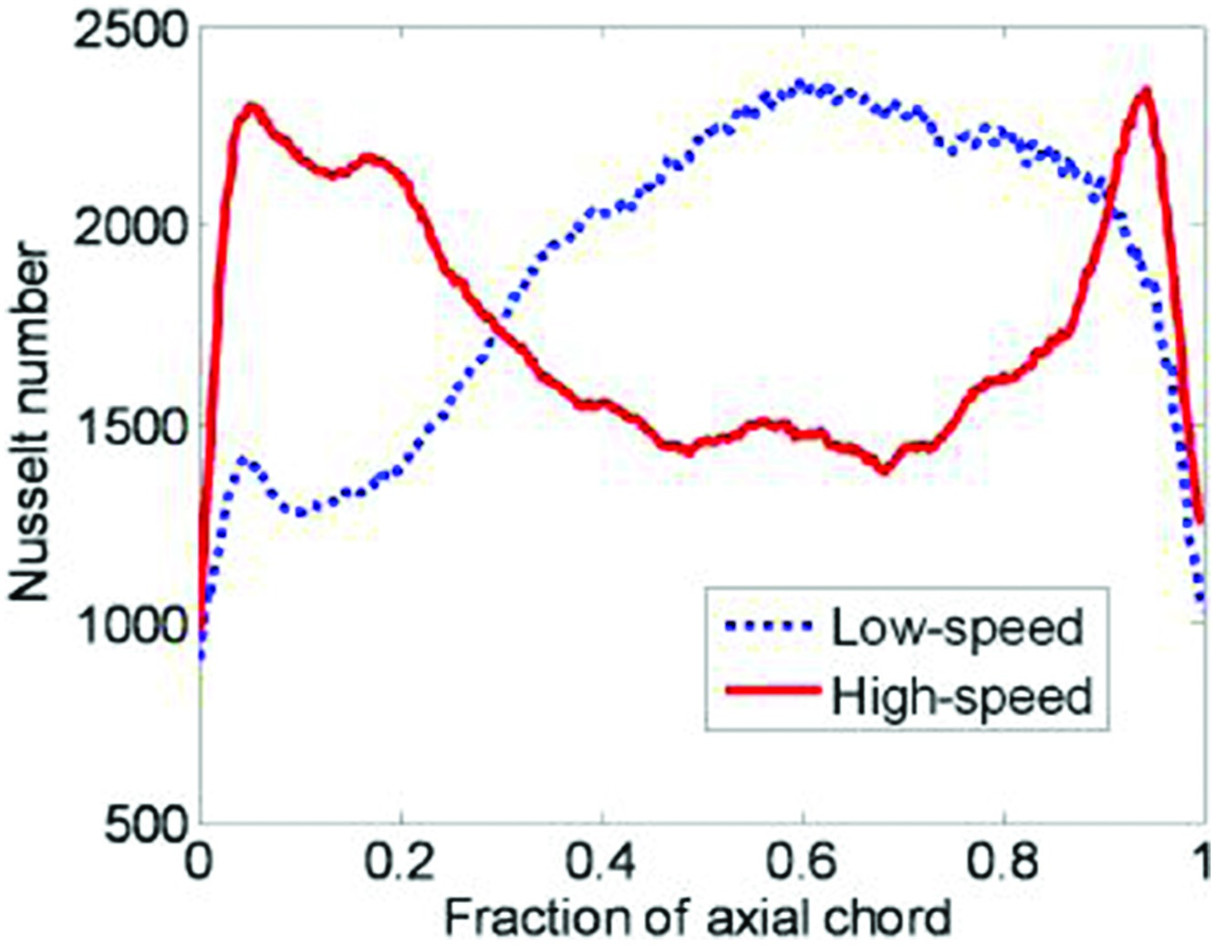
Figure 2 reveals another quite general trend for high speed tip heat transfer. Both experimental and CFD results show that the heat load is high in the frontal region where the OTL flow speed is low, and low in the rear region where the flow is transonic (shown in Figure 1). This overall trend is completely opposite to what has been observed in low speed conditions in the previous research.
Figure 5 demonstrates this qualitative difference by comparing the circumferentially-averaged Nusselt number distributions along the axial distance for a same blade tip at high and low speed conditions 25. Effect of Mach number on local heat flux distribution is illustrated in Figure 6. Note that the high speed blade profile was redesigned for low speed condition to match the blade loading for comparison purposes 38. The results clearly demonstrate that tip heat transfer is a strong function of Mach number with a marked reduction in the heat flux over the rear portion of the tip as the Mach number is increased. The primary cause of this qualitatively different behaviour is attributed to the effective convergent-divergent ducting within a tip gap as the result of the separation bubble at the entrance due to the sharp turning of the flow from the pressure surface side. The opposite pressure gradients in the divergent part of the con-div duct flow between a subsonic and a supersonic flow seem to be chiefly responsible for the differences observed.
Figure 6.
Normalized tip heat flux for blades in high and low speed conditions. (Wheeler et al. [33]).
The qualitatively opposite trends in heat transfer with respect to the flow speed regimes as shown in Figure 5 also provide a direct challenge to the commonly accepted correspondence between flow speed and heat transfer. It is clearly indicated here that a higher speed (higher wall shear stress) does not necessarily lead to a higher heat flux as one would otherwise expect from the Reynolds Analogy.
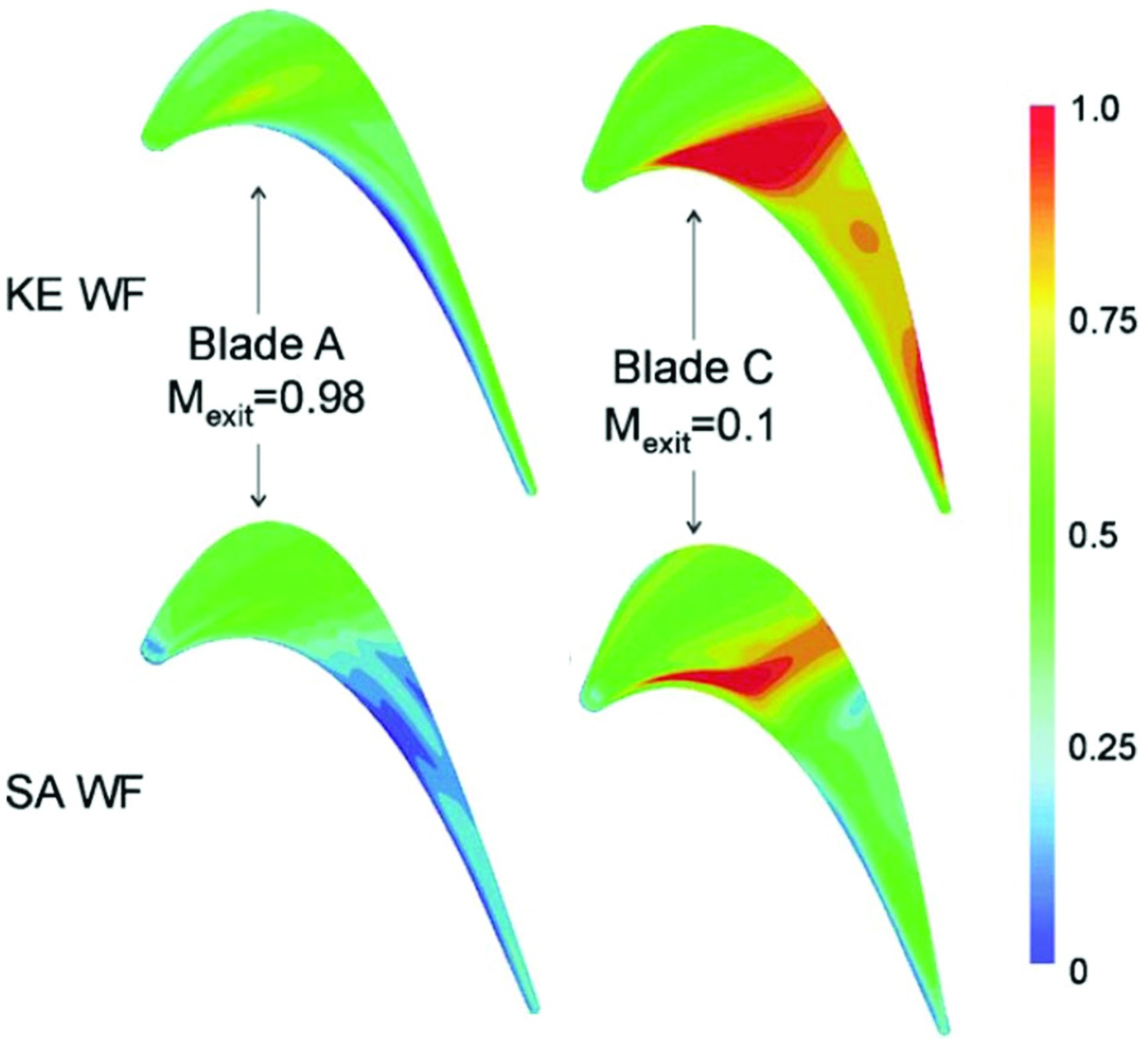
Figure 6 also indicates the high speed tip flow is less sensitive to the choice of turbulence models. This may also be attributed to the favourable pressure gradient (likely to suppress turbulence generation) in the divergence part of the ducting above the separation bubble in a transonic flow.
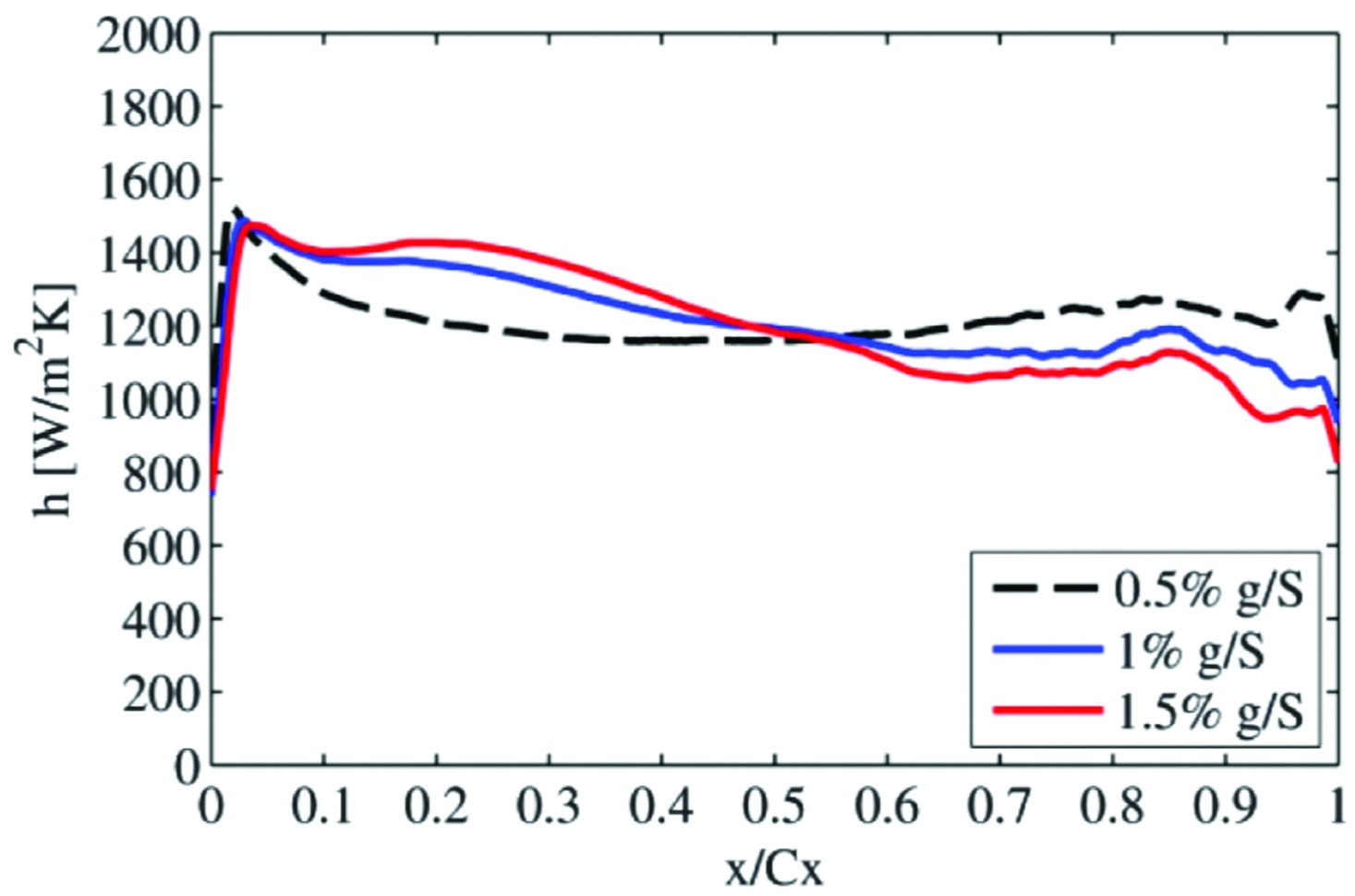
The dependence of heat transfer patterns on OTL flow regime can be further examined by studying the sensitivity of the flow to tip gap size. Circumferentially averaged heat transfer coefficients (HTCs) along axial chord for a transonic flat tip are shown in Figure 7 36. The subsonic flow part (x/Cx<0.5) shows a classic trend of decreasing heat transfer with smaller tip gaps. However, this trend is reversed for the transonic part. Such an opposite trend of the HTC–gap dependence for the subsonic and transonic regions can be linked to the marked reduction of heat transfer in transonic flow as discussed earlier. As the tip gap reduces, the size of the rear transonic region is reduced. The flow regime change from a supersonic state to a subsonic one has seemingly been more influential to the local heat transfer in this case.
All the above studies consistently demonstrate that the conventional wisdoms at low-speed conditions need to be re-examined while the OTL flow reaches a transonic speed. A basic trend and very useful feature for a transonic tip is revealed in Figure 5–Figure 6: high speed OTL flow can be beneficial in terms of heat load.
Tip-shaping for heat transfer management
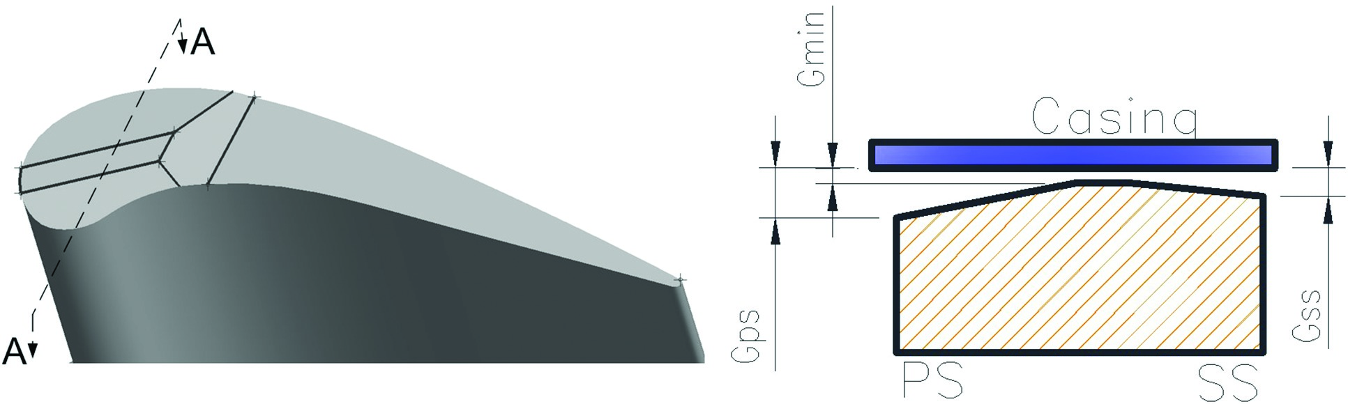
Based on the understanding described in the previous session, a new tip-shaping design was proposed by 15 and reported in detail by 40. The key feature of the design concept is that, around the high heat transfer region over the tip, the tip geometry can be shaped locally to accelerate the over-tip leakage flow to a transonic state. Heat load reduction is expected to be achieved by the local flow acceleration. The shaping is applied to the frontal portion of the blade tip where the heat load is higher and flow is originally subsonic with a flat tip geometry. A shaped tip 3D model and a sectional view are presented in Figure 8. Figure 9 shows the Mach number contours with and without the shaped feature. The tip-shaping design partially forms a convergent-divergent ducting for the local over-tip flow path. The local flow is effectively accelerated and a large portion of the flow field around and after the minimum throat becomes transonic. Figure 9 illustrates a large reduction in local turbulence in the accelerated transonic flow, which seems to be responsible for the low heat transfer behaviour.
Figure 9.
(a) Mach number and (b) Turbulent viscosity ratios on a cut-plane near leading edge (PS on left, SS on right). (Zhang and He [24]).

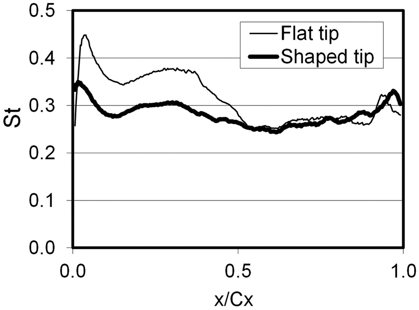
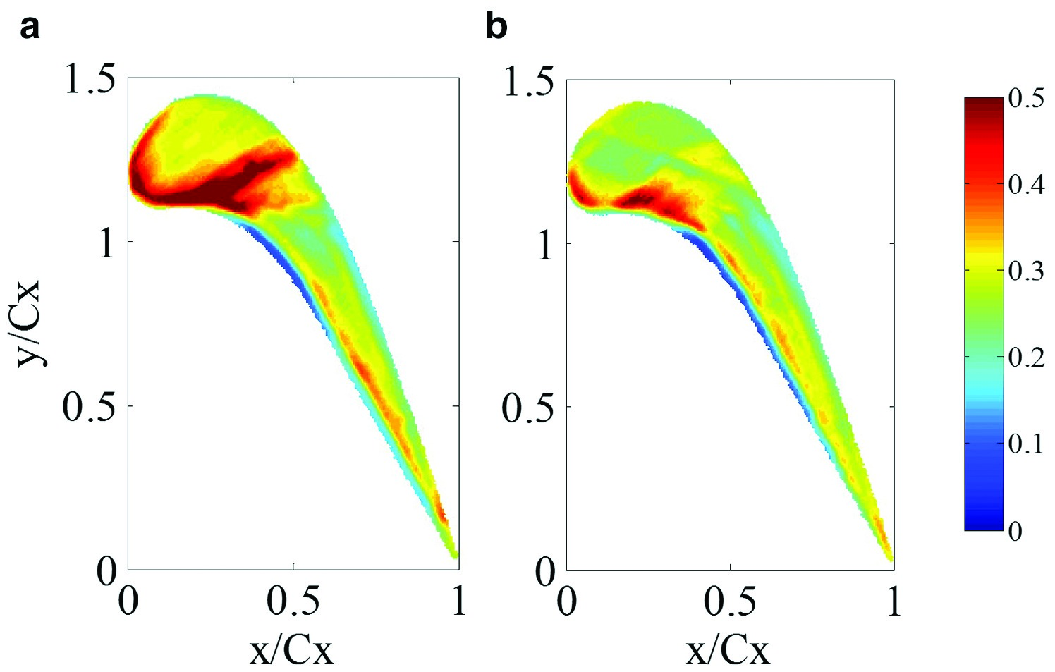
The benefit of tip-shaping has been confirmed by the experimental heat transfer data shown in Figure 10–Figure 11. The high heat load regions in the front part of the flat tip are reduced both in size and intensity with the shaped tip design, as shown in Figure 10. Figure 11 highlights an over 20% overall heat load reduction for the frontal part of the blade, where the shaped feature is provided and the flow is accelerated from a subsonic to a transonic/supersonic state.
Making use of choking to limit OTL flow loss
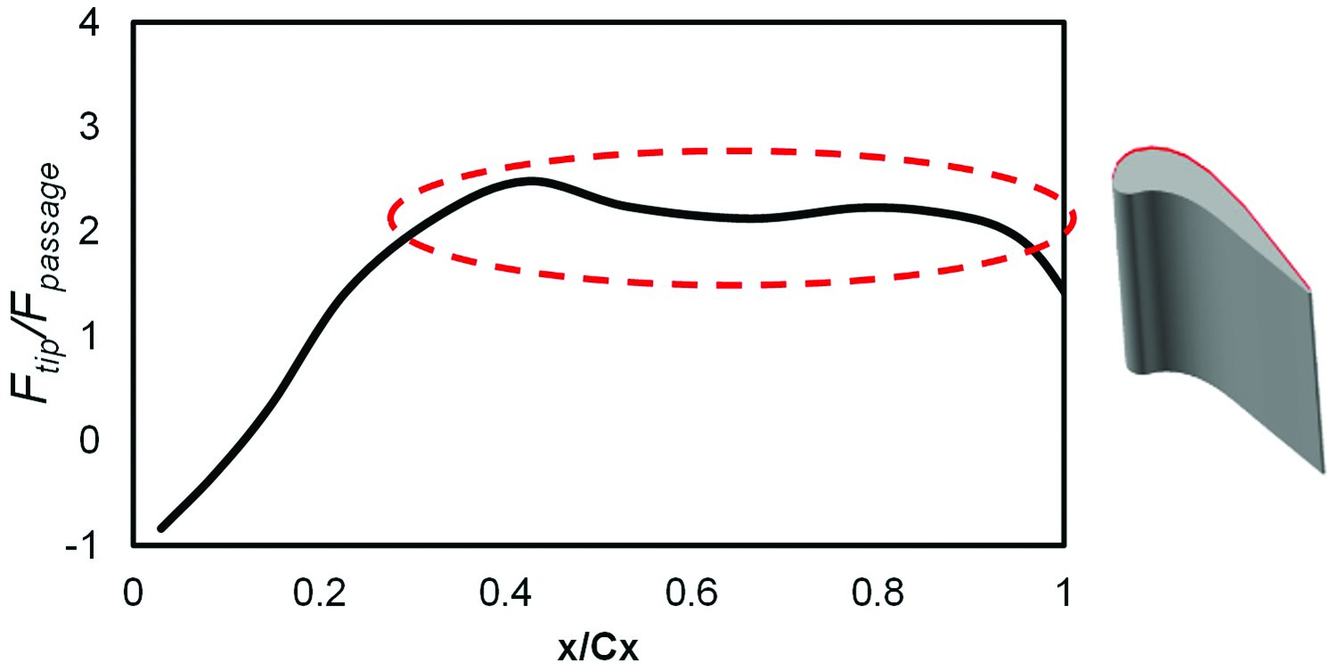
The fact that a large portion of the OTL flow can be supersonic (Figure 1) raises a question on the applicability of the conventional pressure-driven wisdom in tip aerodynamic designs. A choked OTL flow becomes capacity-driven: it is only the pressure surface side total pressure and total temperature which determine the tip leakage mass flow, the influence of the suction surface side is effectively blocked. Figure 12 presents the tip leakage mass flux ratio distribution (the leakage mass flow per unit area, normalized by that for the main passage) along the axial chord direction. Over the rear part of the tip surface (from x/Cx = 0.5 to 1), the tip leakage mass flux ratio stays largely constant. Clearly, a limiter on the leakage flow is set for the tip leakage flow mass flux once the flow is locally choked.
Such decoupling between blade loading and over tip leakage mass flow also has important implications on the loss generation mechanism. 39 showed that the rate of increase in the blade profile loss and secondary flow loss with Mach number outpaces that for tip losses. Consequently, there is a noticeable reduction of the tip leakage loss relatively at the transonic condition.
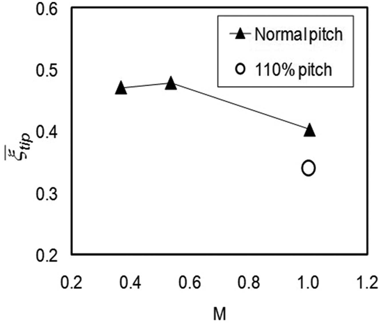
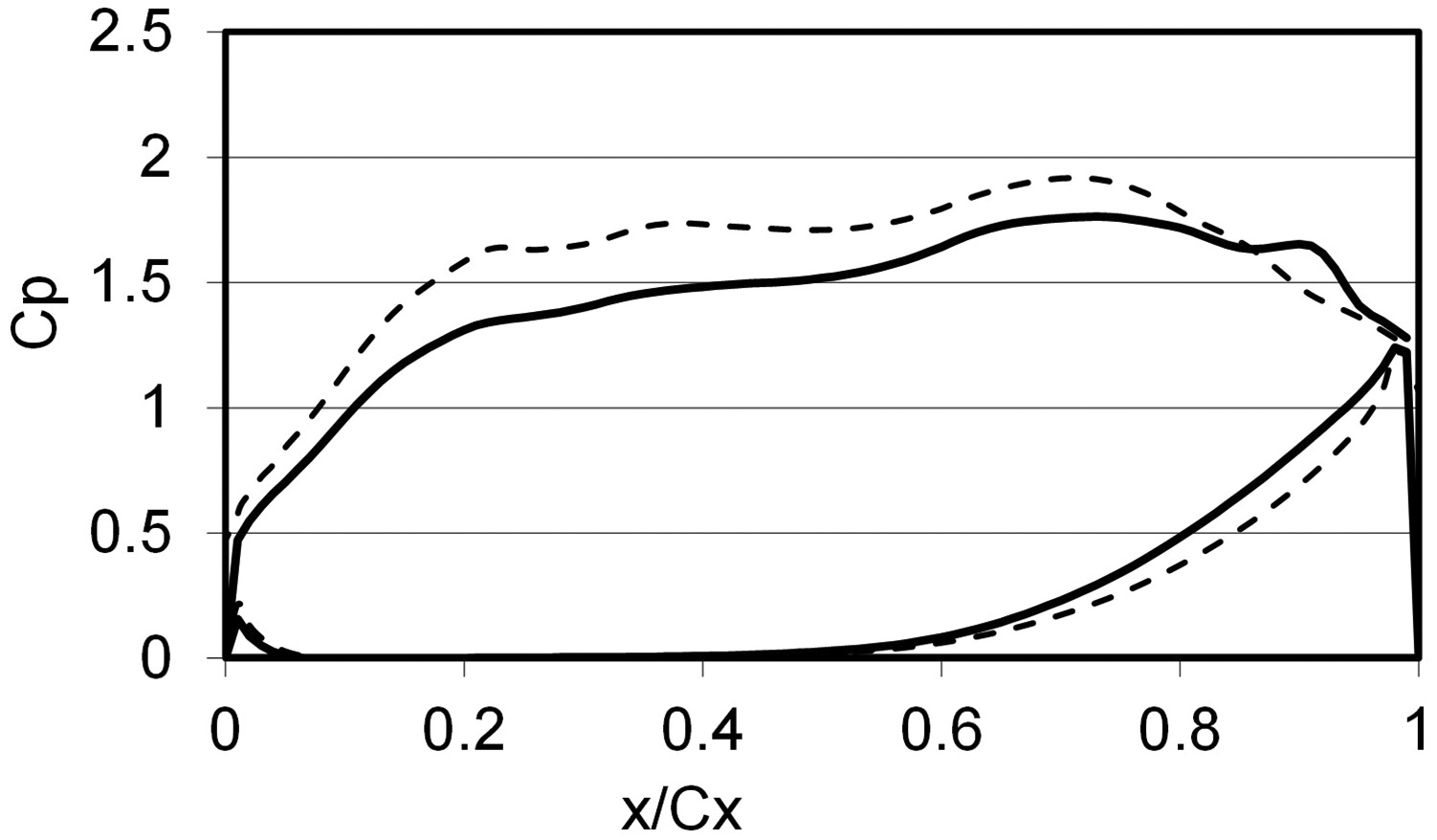
To take advantage of the tip choking feature, 39 explored the potential to design an extra highly loaded blade without proportionally paying additional over tip leakage loss penalty. One simple way to increase the overall blade loading by reducing blade count (increasing blade pitch). The two resulting blade loadings are shown in Figure 13. Figure 14 presents a reduction of relative tip leakage loss coefficient with Mach number and blade loading.
The influence of the OTL flow choking is not limited to flat tip. 20 reported that the transonic squealer tip leakage flow is not sensitive to the cavity depth due to its choking nature, which also contradicts the previous findings in low speed conditions.
Aero-cooling interactions
Cooling injection adds further complexity to the transonic OTL aerothermal performance. In contrast to the conventional understanding on an “effective” film cooling, the interaction between coolant and the base flow can be strong enough to affect the overall OTL flow structure, as reported by 37; Ma et al. (2016) very recently.
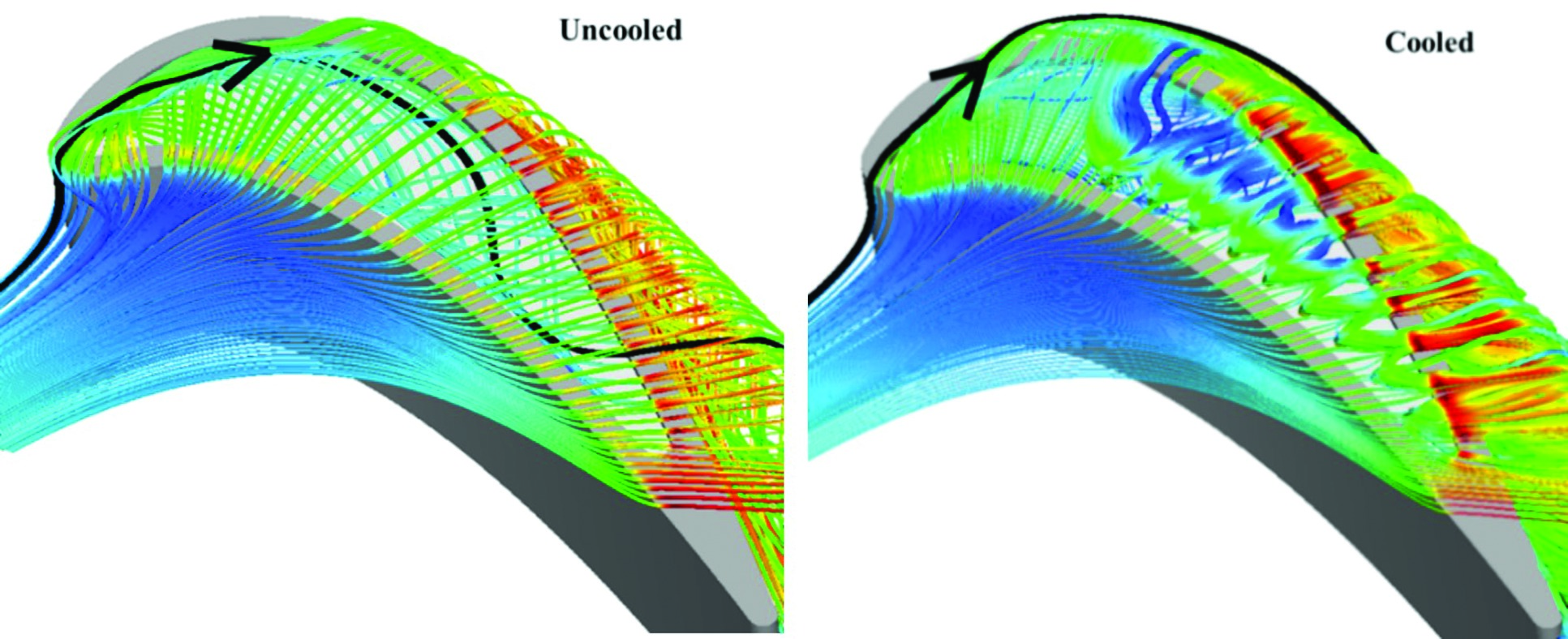
This issue can be illustrated through a series of quasi-3D analyses by 37 for a flat tip and a squealer geometry. In this study, the coolant to inlet total pressure ratio was set to be a typical value of 1.1. Their analysis on detailed flow structure showed that the cooling injection was able to move the tip choking location, impinge on the casing wall, and introduce additional vortical flow structures. A blockage effect of the coolant injection was shown to be considerable even though it was not the primary design intention. Figure 15 and Figure 16 show that the cooling injection introduces distinctive vortical flow structures, which qualitatively altered the flow structure in the squealer cavity, compared to the uncooled case.
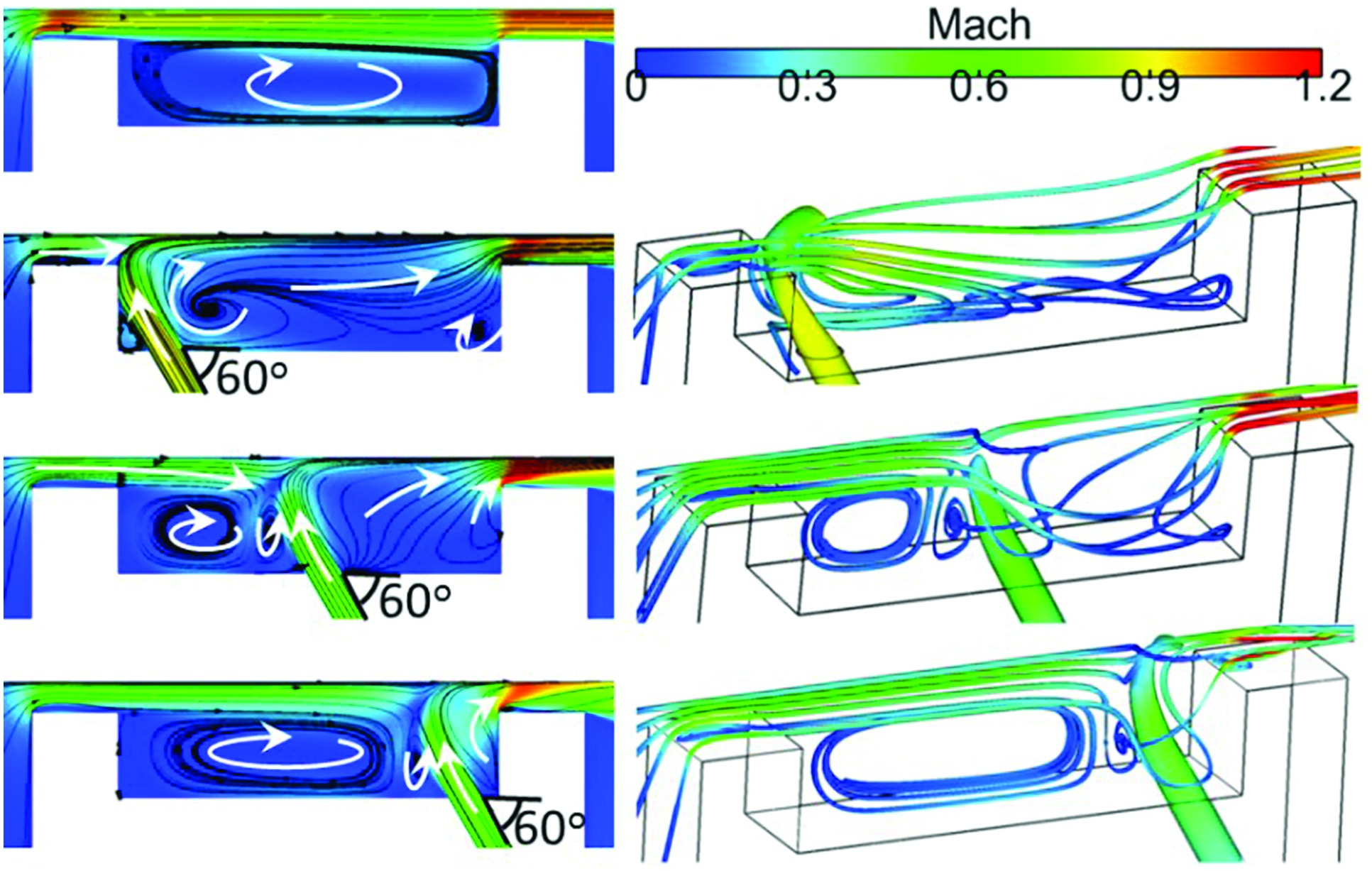
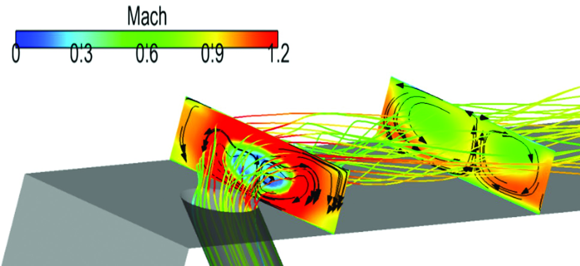
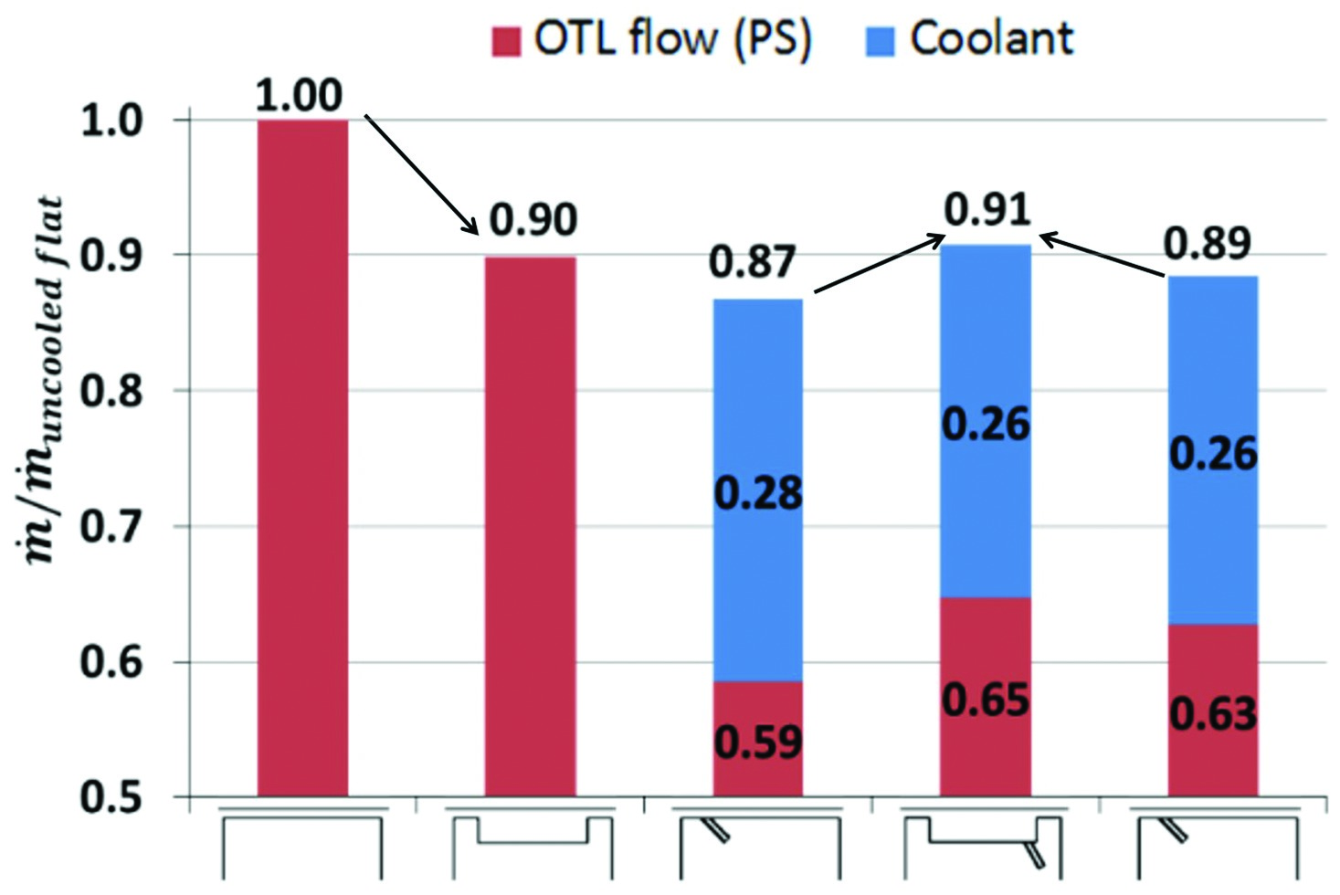
Figure 17 compares overall OTL mass flow rates for flat and squealer tips in both uncooled and cooled conditions. An important observation is that the cooling injection does change the aerodynamic ranking between a flat tip and a squealer tip: a cooled flat tip can outperform a cooled squealer in terms of the OTL mass flow rate in the transonic flow condition at the same pressure ratio and the same amount of coolant flow.
Figure 17.
OTL mass flow rates for cooled flat and squealer tips (indicated in bottom). (Wang et al. [37]).
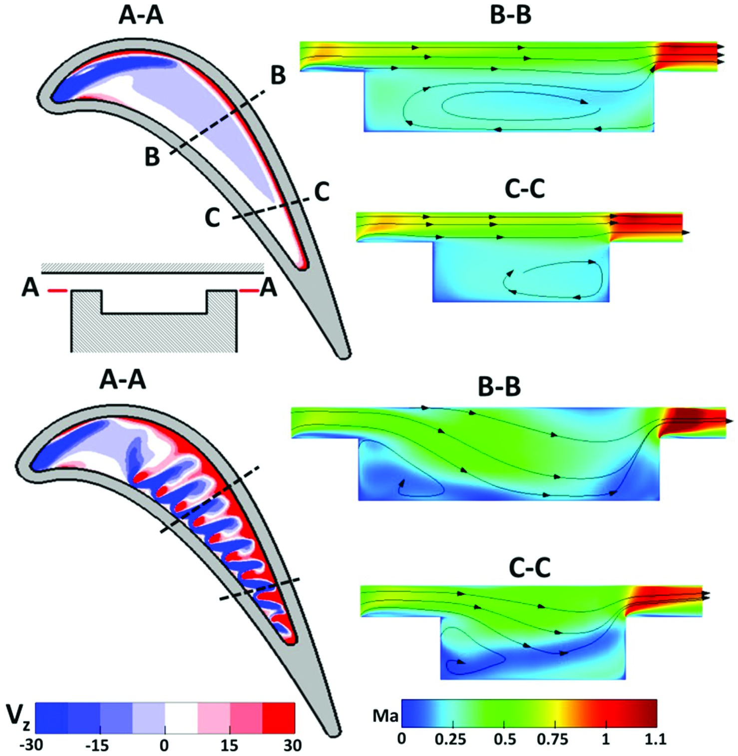
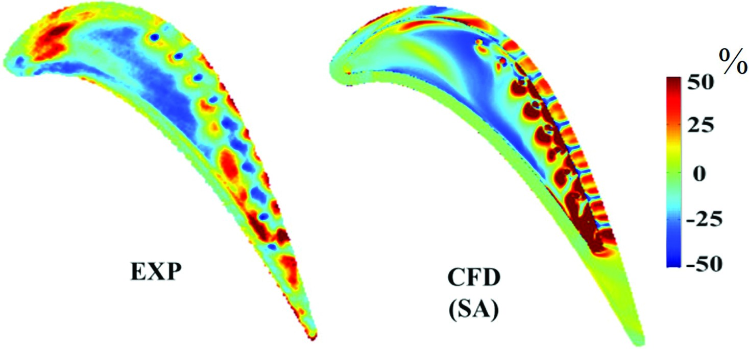
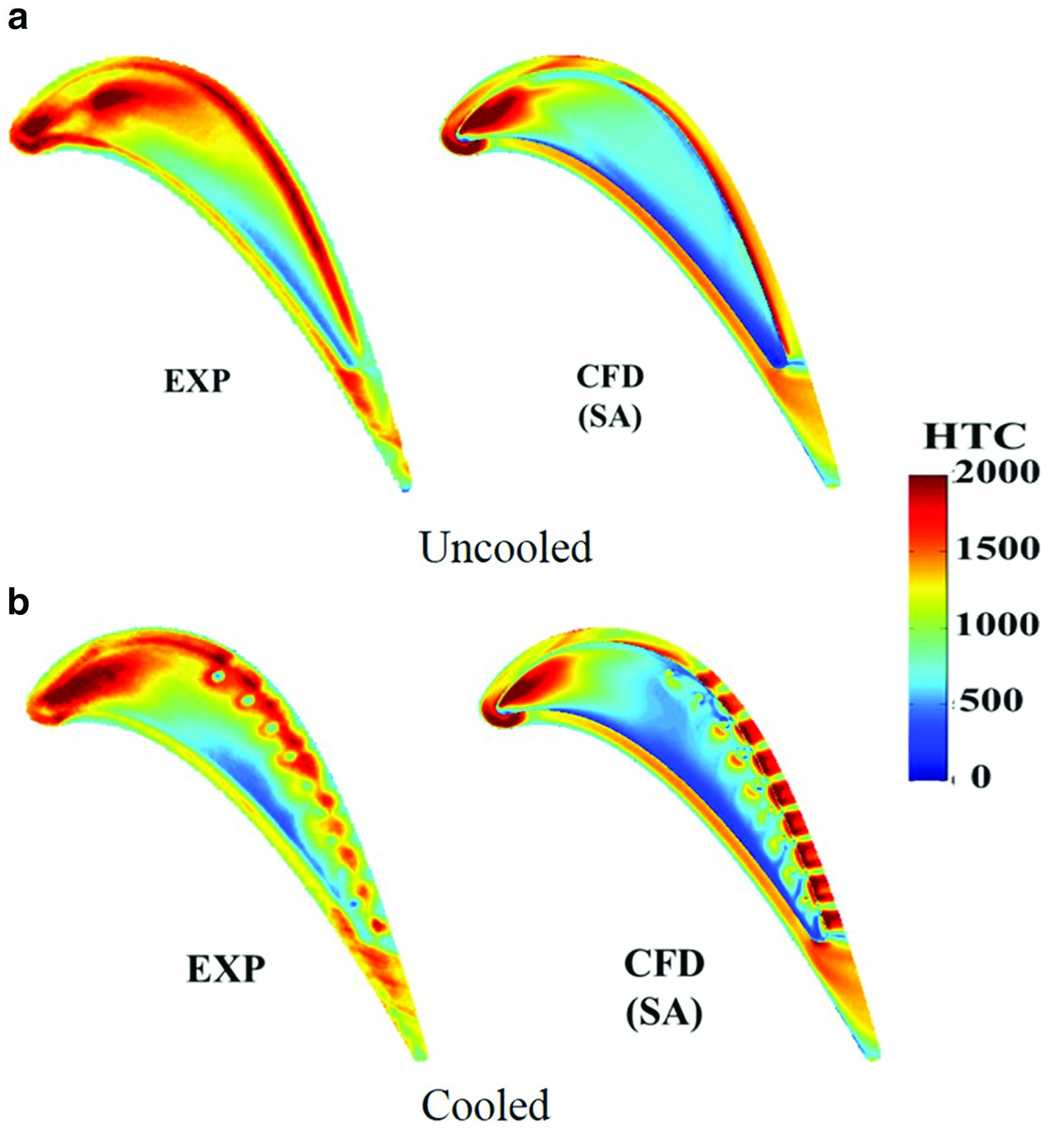
The marked change of OTL aerodynamics with cooling injection was further revealed in the thermal measurement by Ma et al. (2016) in a transonic linear cascade environment. A series of cooling holes were placed with different locations of a squealer tip. Validated by the experimental heat transfer data, their further CFD analyses illustrate the driving aerodynamic mechanisms behind. Figure 18 compares the results of HTC contours for the uncooled and cooled squealer tips. In addition to the distinctly high HTC stripes with the cooling injection, there is a large percentage difference in HTC around the frontal part of the cavity floor, as shown in Figure 19. This upstream region is not expected to be reached by the coolant. The comparison of the flow patterns between a cooled and uncooled tip is shown in Figure 20. Figure 21 plots the distribution of radially averaged OTL mass flux along the axial chord. Both Figures clearly show that the leakage flow near the leading edge is much more influenced by the injection placed from the rear part. Apparently, the impact of cooling flow is neither passive, nor local. Detailed changes in the local flow can be seen in Figure 22. It is particularly noted that even given a relatively small amount of coolant injection, the changes the injection brings to the tip flow is quite pronounced, perhaps equally, or even more pronounced than what one can reasonably expect from certain modifications of local tip geometry.
Figure 22.
Contours of radial velocity over the rim top surface (left) and Mach number on two cut planes normal to the camber line (right). (Ma et al. [39]).

Summary and outlook
The systematic and extensive recent research efforts on high speed turbine blade tip have led to some new findings, some of which are in clear contrast to conventional wisdom and understanding gathered from previous low speed researches.
(1) There is a qualitatively different trend in heat transfer variation between the transonic flow and subsonic flow regimes. The accelerating transonic OTL flow is shown to greatly reduce local turbulence generation.
(2) It has been indicated that there is a potential in taking advantage of the reduction of the heat transfer in a transonic flow in conjunction of limiting OTL by choking. A high payoff could be achieved with further efforts and attention, especially in a context of develop high loading turbines.
(3) There is a very strong interaction between the baseline flow in an uncooled configuration and coolant injection, which has been shown to produce distinctive vortical flow strictures and to alter the local flow markedly. The baseline flow – cooling injection interaction in a tip region appears to be much stronger than its counterpart for the main blade passages, chiefly due to the much confined flow passage involved in the OTL flow.
It needs to be recognised that the main research vehicle for which the above findings are gathered is a high speed linear cascade. Some other aspects, though dealt with to various extent in some recent publications, are not covered in this article, which nevertheless, deserve attention. One of such aspects is the impact of incoming flow conditions, e.g., total pressure and temperature non-uniformities (e.g., 42, 8. It has also been shown that turbine stage inlet velocity and temperature profiles (swirl and hot streak) can have considerable impact on the rotor blade tip heat load 30. Another factor pertinent to the present interest is the relative movement of casing. This can clearly affect the extent of transonic portion of the tip flow as shown computationally by 39, 8, 36. Some recent data for a rotating facility have been gathered by Tamunobere and Acharya (2016). Detailed experimental results for a high speed condition with relative casing movement would certainly be valuable in both validating computational tools as well as clarifying the extent of applicability of the high speed cascade results and associated findings.
In terms of future research as directly suggested and/or implied by the recent findings presented above, the more significant one seems to be the underlined strong interaction between aerodynamics and coolant injection. It is this aspect of strong aero-cooling interactions which would present the most challenge to the conventional approach to blade tip aerothermal design and optimization. It is clear that the coolant is very unlikely to be passively convected by the OTL flow, and the aero-cooling interaction could alter the overall flow structure and aerodynamic ranking. The strong interactions as indicated by some of the recent work, would imply that caution must be exercised when blade tip shape is to be “optimized” purely based on an uncooled configuration.
The strong coolant-base flow interaction in the tip region would suggest that cooling injection can be to some extent considered as a means of flow control. It has been shown that combining flow control and geometry shaping would provide extra performance gain than either shaping or flow control respectively 41.
It is the present authors’ view that optimal tip aero-thermal configurations will have to be a product of a process where the aero-cooling interactions can be taken into account, and more so if the aerodynamics and cooling aspects can be deal with more concurrently. It is worth pointing out that although the high speed aerothermal behaviour has been highlighted, the strong aero-cooling interaction seems to be a prevailing feature regardless of the flow regimes. Therefore, it is suggested that combining tip geometry shaping and cooling injection patterns should be worthy to be researched, particularly in the context of blade tip performance design and optimization, with a potential for more extensive exploitation of tip aerothermal design space.